Design and Development of a Marker-based Augmented Reality
System using OpenCV and OpenGL
Yap Hwa Jentl, Zahari Taha2, Eng Tat Hong", Chew Jouh Yeong"
Centre for Product Design and Manufacturing (CPDM). Faculty of Engineering, University of Malaya.
50603 Kuala Lumpur, Malaysia. Email: [email protected]·
[email protected] jouhyeongtgperdana.um.edu.my"
Abstract. Augmented reality system generates a composite view for the user. It isa combination of the real scene viewed by the user and a virtual scene generated by the computer. In this paper, a webcam based augmented reality system has been developed using OpenCV and OpenCL. Webcam isused to capture the marker tag and image processing technique isused to obtain the required information such as position and orientation. By using this information, virtual images or objects can be created and "pasted" on the marker tag. OpenCV is used to handle real-time image processing and virtual objects are drawn using OpenCL API.
The design and development of the system mainly involves the design of the marker tag. The design criteria of the marker tag have been studied, e.g. shape and colour. An effective market tag has been designed and used to provide the information about the position and orientation to the virtual environment. Virtual objects are drawn
and superimposed with the real-time video captured from the webcam. The virtual objects can be changed through keyboard functions or3Dmodels in STL ASCII format.
Keywords: OpenCv' OpenGL, marker tag, STL ASCII format
1.
INTRODUCTION
Augmented reality (AR) is a growing area in the field of computer generated virtual reality research which deals with the combination of real-world and computer-generated data. Through AR system, user can see real-world superimposed with computer-generated images. The real world environment around us provides a wealth of information that is difficult to duplicate using existing computer graphics technology. This is evidenced by the worlds used in virtual environments. Either these worlds are very simplistic such as the environments created for immersive entertainment and games, or the system that can create a more realistic environment can cost million dollars such as flight simulators.
An augmented reality system generates a composite view for the user. It is a combination of the real scene viewed by the user and a virtual scene generated by the computer that augments the scene with additional information. It can be defined as a combination of real-world and virtual world interactive in real-time 3D environment. The ultimate goal of augmented reality system is to create an environment such that the user cannot tell the difference between the real world and the virtual augmentation of it. To the user of this ultimate
system it would appear that he is looking at a single real scene. AR can be categorized into a few categories depending on their methods of detection. The focus of the paper is on marker-based tracking system.
Marker-based Augmented Reality System is a computer vision based tracking system for Augmented and Mixed Reality applications. Marker-based tracking systems consist of patterns that are mounted in the environment and automatically detected in live video camera using an accompanying detection algorithm. When the user moves the marker. the virtual character moves with it and it appears attached to the real object (Bill inghurst et al. 200 I). Important parameters for such marker systems are their false detection rate (false positive rate), inter-marker confusion rate, minimal detection size (in pixels) and immunity to lighting variation (Fiala 2005).
1.1 Problems Statement
can differentiate between real world and virtual world easily. At the same time, design of the market-tag will also affect the efficient and accurately of the AR system. Most of systems use different shape and pattern for image ~etectio~. which are mostly marker tags in black-and-white. It IS believed that colour pattern will improve the detection result.
1.2
Objectives
This paper is concern with the development of a marker-based aug 'ented reality system using commercial hardware. A compute' webcam was used as the video and image input. The shape - nd pattern of marker tag used is a simple square boundary marker, so that the system can detect direction and orientation easily, The system is developed based on an open architecture' platform using OpenCV and OpenGL module and written in C++ languages.
The system uses image processing technique to obtain the necessary information. Object tracking algorithm was used to extr ct the information of the marker tag, either in static or dyn mic conditions. Therefore, a study of the type of the marker tags, patterns and colours is crucial. This research paper attempts to identify the most efficient and accurate marker design for the developed system.
2 SYSTEM FRAMEWORK
The fundamental process of marker-based augmented reality system is to merge virtual objects with images of a real environment 'r giving more information or making an augmented environment. The transformation between real-world space nd virtual-image plane is represented by a camera matrix, and the marker-based augmented reality system utilizes the camera matrix for merging virtual objects with images. Real-time camera tracking of marker tags are highly dependent on the type of tracking algorithms and marker tags used.
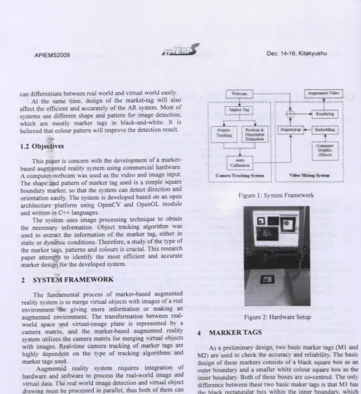
Augmented reality system requires integration of hardware and software to process the real-world image and virtual data. The real world image detection and virtual object drawing must be processed in parallel, thus both of them can be displayed at the same time. Basically, there are two components of the developed AR system, which are the "Camera tracking system" and "Video mixing system". The system framework is shown in Figure I.
3 HARDW ARE SETUP
[image:2.551.36.549.17.577.2]The idea is to have a system that is simple and commercially available. The system consists of a personal computer, with 2.68 GHz. 3.0 GB RAM. NVIDIA GeForce 7300 GS graphics card. a LCD monitor, a Logitech QuickCam E3500 Plus USB webcam, a retort stand and marker tags, as shown in Figure 2.
Figure 1: System Framework
Figure 2: Hardware Setup
4 MARKER TAGS
As a preliminary design, two basic marker tags (Ml and M2) are used to check the accuracy and reliability. The basic design of these markers consists of a black square box as an outer boundary and a smaller white colour square box as the inner boundary. Both of these boxes are co-centred. The only difference between these two basic maker tags is that Ml has the black rectangular box within the inner boundary, which M2 has a black circle inside it.
4.1 Marker Ml
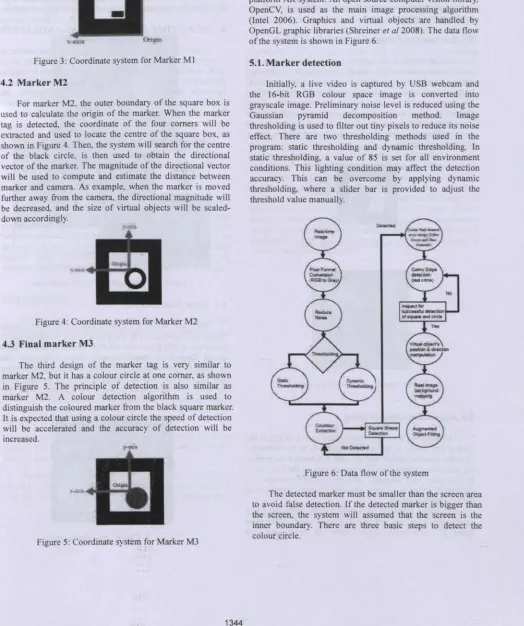
Figure 3: Coordinate system for Marker Ml
4.2 Marker M2
For marker M2. the outer boundary of the square box is used to calculate the origin of the marker. When the marker tag is detected, the coordinate of the four corners will be extracted and used to locate the centre of the square box, as shown in Figure 4. Then, the system will search for the centre of the black circle, is then used to obtain the directional vector of the marker. The magnitude of the directional vector will be used to compute and estimate the distance between marker and camera. As example, when the marker is moved further away from the camera, the directional magnitude will be decreased, and the size of virtual objects will be scaled-down accordingly.
Figure 4: Coordinate system for Marker M2
4.3 Final marker M3
The third design of the marker tag is very similar to marker M2, but it has a colour circle at one corner, as shown in Figure 5. The principle of detection is also similar as marker M2. A colour detection algorithm is used to distinguish the coloured marker from the black square marker. It is expected that using a colour circle the speed of detection will be accelerated and the accuracy of detection will be increased.
Figure 5: Coordinate system for Marker M3
5 SOFTWARE DEVELOPMENT
C++ programming language is used to develop the open platform AR system. An open source computer vision library, OpenCV, is used as the main image processing algorithm (Intel 2006). Graphics and virtual objects are handled by OpenGL graphic libraries (Shreiner et a/2008). The data flow of the system is shown in Figure 6.
5.1.Marker detection
Initially, a live video is captured by USB webcam and the l6-bit RGB colour space image is converted into grayscale image. Preliminary noise level is reduced using the Gaussian pyramid decomposition method. Image thresholding is used to filter out tiny pixels to reduce its noise effect. There are two thresholding methods used in the program: static thresholding and dynamic thresholding. In static thresholding, a value of 85 is set for all environment conditions .. This lighting condition may affect the detection accuracy. This can be overcome by applying dynamic thresholding, where a slider bar is provided to adjust the threshold value manually.
Figure 6: Data flow of the system
Firstly, the system splits the source image into three channel images consisting of red, green and blue channel images. Secondly, it will use edge detection algorithm to extract all the edges of red channel image, and lastly it will used pixel calculation to find the centre of the red circle and mark it on, the output screen.
5.2. Position and Orientation of Virtual Object
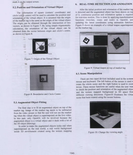
The information of square (comers' coordinate) and circle (cir Ie centre) will be used to calculate the position and orientatio of the virtual object. It is assumed that the origin of the marker tag is the same as the origin of the virtual object. The origin can be obtained through the intersection of two vectors, as .shown in Figure 7. By using simple trigonometry calculation, the orientation of the virtual object can be obtained from the vector between origin and circle's centre, as shown in Figure 8.
Figure 7: Origin of the Virtual Object
Figure 8: Boundaries and Circle Centre
5.3. Augmented Object Fitting
The final step is to fit an augmented object on top of the marker tag. Image of the marker tag needs to be subtracted from the video stream so that the user will not see the marker tag when the virtual object is superimposed on the live video. In this part, only OpenGL will be involved because the augmented object is a virtual object and it deals with a lot of the 3D object drawings.
In order to make the augmented objects looks real when superimposed on the real world. a real world background inside 3D environment created using the texture mapping
approach (Richard 2007). It is used to map the real-time image taken from webcam to the window's background of computer-generated 3D world. After this, any virtual 3D object can be drawn in front of the mapped image and it will just look like the virtual objects are on top of the real world.
6. REAL-TIME DETECTION AND ANIMATION
[image:4.544.12.539.202.818.2]After the initial position and orientation of the marker tag is detected and the augmented object has been drawn on top of it, continuous position and orientation update is required for real-time motion. This is done by applying transformation functions (translate, rotate and scale) in OpenGL and updating the latest coordinates using animation function. Figure 9 shows an example of a virtual teapot superimposed on the marker tag.
Figure 9: Virtual teapot on top of marker tag 6.1. Scene Manipulation
There are two input devices included used in the system: mouse and keyboard. The left button of the mouse is used to rotate the whole scene and the right button is used to zoom in/out. These mouse functions are useful when the user want to check the position and orientation of the augmented object and the texture mapped background in 3D space from different viewing directions. Figure 10 illustrates the virtual scene that been rotated using the mouse buttons.
The keyboard is used to select the augmented objects and toggle the animation on/off. Other keyboard functions include "reset" option to reset all the view to the beginning view and "calibration" option to show the windows for threshold values. Figure 11 shows an example of a STL 3D model loaded into the system.
Figure 11: STL 3D Model in AR System
7. CONCLUSION
As a conclusion, a Marker-based Augmented Reality System has been successfully developed, based on an open platform architecture. It is developed using C++ language, with OpenCV as the image processing tool and OpenGL as the graphics API. A study of different designs of marker tags has been done. It was found that the use of colour marker tag enhances the efficiency and accuracy of the detection process.
REFERENCES
Billinghurst M., Kato H., Poupyrev I. (2001) The MagicBook: A Transitional AR Interface, Computers and Graphics, 745-753.
Fiala M. (2005) ARTag, A Fiducial Marker System using Digital Techniques, Proceedings of the 2005 IEEE Computer Society Conference on Computer Vision and Pattern Recognition (CVPR'05). 2, 590 _ 596.
Intel Corporation (2006) Open Source Computer Vision Library, OpenCV Documentation.
Richard S. Wright, Jr., Benjamin Lipchak. Nicholas Haemel (2007) OpenGL Superliible: Comprehensive Tutorial and Reference Addison-Wesley.
Shreiner D., Mason Woo, Neider J., Davis T. (2008) OpenGL Programming Guide: The Official Guide to Learning OpenGL, 6th edition Addison-Wesley Professional.
AUTHOR BIOGRAPHIES
Yap Hwa Jen is a researcher cum PhD student in the Centre of Product Design and Manufacture (CPDM), University of Malaya, Malaysia. He is also a Lecturer in the Department of Engineering Design and Manufacture, Faculty of Engineering, University of Malaya, Malaysia. He obtained his bachelor degree in Mechanical Engineering with Honors from the University of Malaya in 2000 and Master of Engineering Science from University of Malaya in 2005. His research interests included virtual reality, human-computer interface, product design, robotics and automation. His email address is <[email protected]>