International Journal of Emerging Technology and Advanced Engineering
Website: www.ijetae.com (ISSN 2250-2459, ISO 9001:2008 Certified Journal, Volume 7, Issue 12, December 2017)
1
Analysis, Design and Passivity-Based Control of a Boost
Converter Used With a Fuel Cell
Ahmed Moutabir
1, Elhassan Abdelmounim
2, Mohamed Aboulfatah
3 1,2,3Hassan 1st University Faculté des Sciences et Techniques, Settat MoroccoAbstract—In this work, a study and control of a fuel cell system are developed. First, a model of a fuel cell is presented and simulated. Then, the boost converter used is described and modelled. A non-linear robust passivity based control is synthesised. Finally, the simulation models have been developed and tested in the MATLAB / SIMULINK. Simulated results are displayed to validate the feasibility and the effectiveness of the proposed strategy
Keywords— Fuel cell, passivity based control, Euler Lagrange, zeros dynamics, Lyapunov.
I. INTRODUCTION
To meet the requirement of reduction of greenhouse gas emission a lot of works is being made on the grid in order to make it smarter and less polluting, but also many concepts using new technics and technologies are being integrated.
The fuel cell is one of the most promising sources of renewable energy[1]. They can be considered as green power because they are environmentally clean, have low emission of oxides of nitrogen and sulfur and at the same time, they can operate with a very low level of noise. In addition, they can provide energy in a controlled way with higher efficiency than conventional power plants.
Fuel cells are electrochemical devices which convert chemical energy into electrical energy directly by oxidizing fuel (hydrogen) without intermediate thermal or mechanical processes. They are efficient, scalable and silent devices that can provide power to a wide variety of utilities, from portable electronics to vehicles, to electric grids. They are categorized mainly on the type of electrolyte used, operating conditions or fuel.
Obtaining a high voltage is needed in some applications using a fuel cell. The problem can be handled either by using a simple step-up converter with high duty cycle or by using cascaded converters [2].
A DC/DC converter has the objective of transforming the power from a source (in our case a fuel cell) into an appropriate form. There are different topologies of converters. The most used is the boost converter, that increases voltage from input to output.
Considering nonlinear characteristic of the DC-DC converters, it is better to use a nonlinear control technique in output voltage regulation. Main nonlinear controllers are feedback linearization, sliding mode [3], backstepping [4] and passivity-based control [5].
In this work, a passivity based control approach is applied to a boost converter used with a fuel cell.
The paper is organized as follows: the fuel cell model is presented in section 2, the system under study (i.e. the DC-DC boost converter) is modeled and given a state space representation in Section 3. The controllers design, the closed-loop system analysis and the controller performances which illustrated through numerical simulations are dealt in Section 4. In section 5, the conclusion is presented.
II. FUEL CELL MODEL
A.Operation principle of a PEMFC
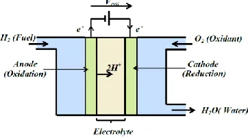
PEM fuel cell is composed of a cathode and an anode electrode, which are separated by a polymer electrolyte membrane. Fig.1 illustrates the basic scheme for a single PEM fuel cell [6].
[image:1.612.351.532.527.628.2]It is a controlled electrochemical combustion of hydrogen and oxygen, with simultaneous production of electricity, heat and water, based on a chemical reaction.
Fig 1. Scheme of a single PEM fuel cell
Generally, the electrochemical operation principle of a PEM fuel cell is described by two chemical reactions and may be summarized as follows:
International Journal of Emerging Technology and Advanced Engineering
Website: www.ijetae.com (ISSN 2250-2459, ISO 9001:2008 Certified Journal, Volume 7, Issue 12, December 2017)
2
H2 → 2 H+ + 2 e
-- In the cathode and in contact with both electrons and protons, the oxygen (oxidant) is reduced to water. The reduction reaction is given by:
½O2 + 2 H
+
+ 2 e- → H2O
- The overall reaction is:
H2 + ½O2 → H2 O
An electromotive force is generated between the two electrodes during electrical reactions and electron transfer process. In order to meet the required amount of power, many single cells can be assembled into a fuel cell stack.
B.PEM fuel cell modeling
The model of PEM fuel cell proposed in Ref.[7] is considered in this paper.
The output voltage of a single fuel cell is given by:
(1)
where ENernst represents the open cell voltage, Vact represents the activation potential, Vohm represents the ohmic potential and Vconc represents the concentration potential.
The open cell voltage is defined as follow:
( ) * ( ) ( )+ (2)
where PH2 and PO2 are respectively, the partial pressure of hydrogen and oxygen, and T the temperature in Kelvin.
The potentials representing the voltage losses are given by the following expressions
( ) ( ) (3)
( ) (4)
(
) (5)
Where icell is the cell current and ξ1, ξ2, ξ3 ,ξ4 are the parametric coefficients for cell model;
is the concentration of oxygen given by
( )
(6)
RM and RC are, respectively, the equivalent membrane resistance and contact resistance between the membrane and electrodes. RMcan be calculated as:
(7)
Where: l, A and ρM are, respectively, the thickness (cm), the activation area (cm2) and the specific resistively (Ωcm) of the membrane. ρMcan be obtained by:
[ (
) (
) ( ) ]
[ ( )] * ( )+
(8)
Where ψ is the water contents of the membrane.
B is a parametric coefficient (V) that depends on the cell and its operation condition. J is the actual cell current density (A/cm2), and Jmax is the maximum value of J.
J = icell / A (9)
For a stack with n cells, the voltage Vfc can be calculated by
Vfc = n.Vcell (10)
Finally, the power is defined by:
P=Vfc .icell = n.Vcell .icell (11)
As long as the unknown parameters are determined, the output Vfc corresponding to a certain current icell can be predicted.
C.Simulation results
The PEM fuel cell model has been simulated by using Matlab software with the set of parameter values depicted in Table:
TABLE I
PARAMETEROF FUELCELL
Parameters Values Parameters Values
PH2 ,PO2 2.105 Pa ψ 23
ξ1 -0,922 T 343K
ξ2 0,00312 Jmax 2A/cm
2
ξ3 -9,92.10
-5
A 100cm2
ξ4 7,4.10-5 RM + RC 0,4.10- 4Ω
VFC 60V PFCmax 8kW
International Journal of Emerging Technology and Advanced Engineering
Website: www.ijetae.com (ISSN 2250-2459, ISO 9001:2008 Certified Journal, Volume 7, Issue 12, December 2017)
[image:3.612.68.267.145.259.2]3
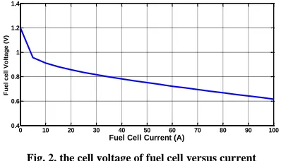
Fig. 2. the cell voltage of fuel cell versus currentIII. DC-DCBOOST CONVERTER MODELLING
A. Switched and Euler Lagrange models
[image:3.612.58.278.348.525.2]The circuit in fig.2 consists of a DC-DC boost converter. It is according to the known pulse wide modulation (PWM) principle.
Fig. 3. the fuel cell system scheme
The switched model of a system can be represented by the following differential equations:
( ) ( )
( )
( )
The averaged model is defined as follows:
̇ ( ) ( )
̇ ( )
( )
In the above model x1, x2 and are denoted, respectively, the averages inductor current iL, capacitor voltage VCandduty ratio u.
These equations can be rewritten in Euler-Lagrange (EL) form as follows:
̇ ( )
Where:
( ) ( ) is the system state variable vector,
(
)is the positive definite diagonal matrix,
(( ) ( )) is the anti-symmetric matrix ( ) which reflects the system internal interconnection structure; ( ) is the system
dissipation element matrix which reflects the system dissipation characteristics; and ( ) is the system external input vector.
B. Equilibrium points
Using the average state representation, considering ̇ and solving the following system
{ ( ) ( )
We obtain
{
( ) ( ) ( ) ( )( )
C. Zeros dynamics
Using the equations (14) and (15)
̈ ( ̇ ) ̇ *( ) ̇ + ( ) ( )
If we consider the equilibrium point: and
At the equilibrium point: ̈ ̇ then the equation (17) becomes
*( ) ̇
( ) + ( )
(18)
Finally we obtain the zeos dynamics of a boost converter [8]:
0 10 20 30 40 50 60 70 80 90 100
0.4 0.6 0.8 1 1.2 1.4
Fuel Cell Current (A)
F
u
e
l
c
e
ll
V
o
lt
a
g
e
(
V
International Journal of Emerging Technology and Advanced Engineering
Website: www.ijetae.com (ISSN 2250-2459, ISO 9001:2008 Certified Journal, Volume 7, Issue 12, December 2017)
4
̇ ( )
* ( )
+ (19)
The equilibrium points of (19) are given by:
{
√(
)
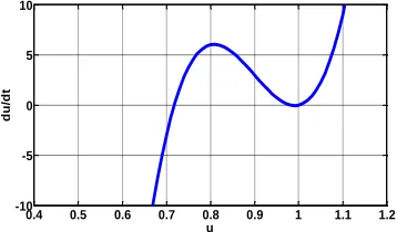
If we consider r=0, we obtain the equilibrium value:
which has a physical significative,
[image:4.612.63.242.302.407.2]provided .This fact confirms the amplifying features of the boost converter [5].
Fig. 4. Zeros dynamics of the boost converter corresponding to average output voltage
IV. CONTROL DESIGN
There are three operational control objectives:
(i) Regulating the output voltage to a desired value .
(ii) Ensure the global stability of the system. (iii) Ensure the robustness of the system.
Let denotes the tracking error matrix and consider the desired error dissipation matrix defined by:
, ( ) (20) Where denotes the injected damping and are positive constants.
Performing a damping injection ensures the desired asymptotic behavior of the output error dynamics.
Using the equations (16) and (20), and replacing by ( ) the error dynamics with desired damping become
̇ ( ̇ ) (21)
The control laws will be define by the following expression
( ̇ ) (22)
In this case the error dynamics is defined by:
̇ ( ) We define the total energy as a Lyapunov function for equation (23) as follows:
To get a stabilizing control laws, the time-derivative ̇ must be a negative definite function of z. Then ̇ is chosen
as: ̇ for z ≠ 0
Consider the expression: ̇
which corresponds to the following scalar differential equations :
{ ̇ ( ) ̇ ( )
The control law and the desired inductor current are defined by
{
[ ̇ ]
[ ̇ ]
D. Simulations results
In order to verify the theoretical results predicted in Sections II and III, the fuel cell system boost converter has been simulated by using SIMPOWER of Matlab-Simulink software with the set of parameter values depicted in Tables I and II.
TABLE III
PARAMETERSOF CONVERTER
Parameters Values
F 10kHz
L 0,3H
r 0,05Ω
R 10Ω
C 5mF
Vdcref 200V
0.4 0.5 0.6 0.7 0.8 0.9 1 1.1 1.2
-10 -5 0 5 10
u
d
u
/d
International Journal of Emerging Technology and Advanced Engineering
Website: www.ijetae.com (ISSN 2250-2459, ISO 9001:2008 Certified Journal, Volume 7, Issue 12, December 2017)
[image:5.612.62.275.140.652.2]5
Fig. 5. The load current variationFig. 6. the fuel flow rate
Fig. 7. the fuel cell voltage
[image:5.612.333.547.142.511.2]Fig.8. the fuel cell current
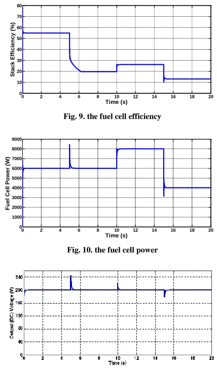
Fig. 9. the fuel cell efficiency
Fig. 10. the fuel cell power
Fig. 11. the output voltage (dc voltage)
We remark that the voltage of the fuel cell increases (Fig.7) with the fuel flow rate (Fig.6). For a variation of the voltage of the fuel cell, the current varies (Fig.8) which is justified by the polarization curve. Fig.9 and Fig.10 shown respectively the efficiency and the power of fuel cell resulting of different variations.
Robustness is ensured: when changing the voltage of the fuel cell or the load current, the bus voltage reacts but returns to its desired value (Fig.11).
The variations of the load current are reflected directly on the fuel cell, which is not desirable hence the need to hybridize it.
0 2 4 6 8 10 12 14 16 18 20
0 20 40 60 80 100 Time (s) L o a d Cu rr e n t ( A )
0 2 4 6 8 10 12 14 16 18 20
0 50 100 150 200 Time (s) F u e l F lo w R a te ( lp m )
0 2 4 6 8 10 12 14 16 18 20
20 30 40 50 60 70 80 Time (s) F u e l C e ll V o lt a g e ( V )
0 2 4 6 8 10 12 14 16 18 20
0 20 40 60 80 100 120 140 160 180 Time (s) F u e l C e ll Cu rr e n t ( A )
0 2 4 6 8 10 12 14 16 18 20
0 10 20 30 40 50 60 70 80 Time (s) S ta c k E ff ic ie n c y ( % )
0 2 4 6 8 10 12 14 16 18 20
International Journal of Emerging Technology and Advanced Engineering
Website: www.ijetae.com (ISSN 2250-2459, ISO 9001:2008 Certified Journal, Volume 7, Issue 12, December 2017)
6
V. CONCLUSION
In some applications, such as fuel cell systems, high conversion ratios are needed. Different techniques and converter topologies can be obtained to handle this problem. In this paper, the boost converter has been studied for his potential use in this kind of applications. It has been analyzed theoretically and by numerical simulations using Matlab software. The dynamical models and stability analysis of this system have been presented. The controller design has been studied as well. The results of simulations have been satisfied.
REFERENCES
[1] J. C. Amphlett, R. M, Baumert, R. F. Mann, B. A. Peppley, P. R. Roberge. Performance modeling of the ballard mark IV solid polymer electrolyte fuel cell. J Electrochem Soc 1995; 142(1):1e15. [2] O. Hegazy, J.Van Mierlo, and Ph. Lataire. Analysis, Modeling, and
Implementation of a Multidevice Interleaved DC/DC Converter for Fuel Cell Hybrid ElectricVehicles, IEEE Transactions on power electronics, vol.27, N°.11, pp.4445–4457, Novembre 2012
[3] A. Elmaguiri, F. Giri, A. Abouloifa, F.Z. Chaoui. Robust control, Elsevier (2010)
[4] J. Alvarez-Ramirez, G. Espinosa-Perez, D. Noriega-Pineda. Banaszak Backstepping approach. IEEE., 190 (2001)O. Hegazy, J.Van Mierlo, and Ph. Lataire. Analysis, Modeling, and Implementation of a Multidevice Interleaved DC/DC Converter for Fuel Cell Hybrid ElectricVehicles, IEEE Transactions on power electronics, vol.27, N°.11, pp.4445–4457, Novembre 2012 [5] Sira-Ramirez H., Perez-Moreno R.A., Otega R. et al.,
"Passivity-based controllers for the stabilization of DC to DC power converters" . Automatica 33(4): 499-513 (1997).
[6] S. Yuvarajan and D. Yu, ―Characteristics and modeling of pem fuel cells,‖ Proceedings - IEEE International Symposium on Circuitsand Systems, vol. 5, pp. –880–883 –, 2004
[7] J.M.Correa, F.A.Farel, L.N.Canha, M.G.Simoes "An Electrochemical Based Fuel Cell Model Suitable for Electrical Engineering Automation Approach," IEEE Transactions on Industrial Electronics, vol. 51, pp. 1103-1112, Oct 2011.
[8] H.Sira Ramirez and al,‖passivity based regulation of a class of multivariable DC to DC power converters‖ 13th Triennial World Congresso, San Fransisco, USA, pp:333-338 (1996).
AUTHORS’ INFORMATION
1HASSAN 1st University of Settat, Laboratory Analysis of Signal and
Information Processing from the Faculty of Science and Technology, BP 577, Settat Morocco. (e-mail: [email protected]).
2HASSAN 2nd University of Casablanca Mohammedia, Faculty of
Sciences Ain Chock, Casablanca, Morocco.
Moutabir Ahmed was born in 1965 in Casablanca, Morocco. He received the Engineer degree in electrical Engineering from High Institute of Technical Education (ENSET) of Mohammedia in 1989.
In 1996, he successfully passed the external aggregation contest. He obtained his Master in Automatic, Signal Processing and Industrial Computing from Faculty of Sciences and Technics, University Hassan First, Settat, Morocco.
Since 1995, he joined the technical school Alkhaouarimy of Casablanca where he teaches in classes BTS "Technician Certificate Superiors" in Casablanca, Morocco and pursues his doctoral studies at the University Hassan first Settat. His main research interests and experience include analysis, design, and control of power converters and renewable energy applications.
Elhassane Abdelmounim received his PhD in applied Spectral analysis from Limoges University at science and technical Faculty, France in 1994. In 1996, he joined, as Professor , applied physics department of science and technical faculty, Hassan 1st University, Settat, Morocco
His current research interests include digital signal processing and machine learning. He is currently coordinator of a Bachelor of Science in electrical engineering and researcher in ―ASTI‖ System Analysis and Information Technology Laboratory at science and technical faculty, Hassan 1st University, Settat, Morocco.
Mohamed aboulfatah was born in Casablanca Morocco in 1967, he received his PhD in Measures and Instrumentation from Bordeaux University, France in 1994.
From 1993 to 1995 he was associated professor at the Technological Institute of Bordeaux University.
In 1996, he joined, as permanent Professor, applied physics department of science and technical faculty, Hassan 1st University, Settat, Morocco.