A GENERIC COMPONENT MODEL FOR BUILDING
SYSTEMS SOFTWARE
Geoff Coulson, Gordon Blair, Paul Grace, Francois Taiani, Ackbar Joolia, Kevin Lee,
Jo Ueyama, Thirunavukkarasu Sivaharan
Computing Department, Lancaster University, UK
contact: [email protected]ABSTRACT
Component-based software structuring principles are now commonly and successfully applied at the application level; but componentisation is far less established when it comes to building low-level systems software. Although there have been pioneering efforts in applying componentisation to systems-building, these efforts have tended to be narrowly targeted at specific application domains (e.g. embedded systems, operating systems, communications systems, programmable networking environments, or middleware platforms). They also tend to be narrowly targeted at specific deployment environments (e.g. standard personal computer (PC) environments, network processors, or microcontrollers). The disadvantage of this narrow targeting is that it fails to maximise the genericity and abstraction potential of the component approach. In this paper we argue for the benefits and feasibility of a generic yet tailorable approach to component-based systems-building that offers a uniform programming model in a wide range of target domains and deployment environments. More specifically, we present our OpenCom component model which is explicitly tailorable to diverse domains and environments. The component model is supported by a reflective runtime architecture that is itself built from components. After describing OpenCom and evaluating its performance and overhead characteristics, we present and evaluate two case studies of systems we have built using OpenCom technology, thus illustrating its benefits and its general applicability.
1. Introduction
Application-level component-based software is now well established. Prominent examples include: browser plug-ins [Mozilla,05], JavaBeans and Enterprise JavaBeans [Sun,05], the CORBA Component Model [OMG,99], Microsoft’s .NET [Microsoft,05], and ICENI Grid components [Furmento,02]. Overall, some key characteristics of the component approach are as follows: i) it promotes a high degree of genericity and abstraction in software design, implementation, and deployment, which leads to higher programmer productivity; ii) it facilitates flexible configuration of software (and, potentially, run-time reconfiguration), and iii) it fosters third-party software reuse [Emmerich,02].
A broadly-accepted definition of software components is that they are “units of composition with contractually-specified interfaces and explicit context dependencies only ... that can be deployed independently and are subject to composition by third parties” [Szyperski,98]. Some component models restrict composition to build time or load time, but many (including all of the above) additionally support the composition of components at run time. The “explicit context dependencies” aspect of the definition means that third parties can straightforwardly deploy independently-developed components into established runtime software environments. Deployment is straightforward because it is clear and explicit what a newly-deployed component expects from its environment.
[Ommering,00]; proposals for componentised operating systems (OSs) include THINK [Fassino,02], OSKit [Ford,97] and MMLITE [Helander,98]; proposals for componentised programmable networking environments
include VERA [Karlin,01], MicroACE [Johnson,03], and Netbind [Campbell,02]; and proposals for componentised middleware platforms include LegORB [Roman,00], k-Components [Dowling,01] and various JavaBeans-based approaches (e.g. [Bruneton,00] and [Joergensen,00]).
However, all of these efforts suffer from the key limitation that they are narrowly targeted. This applies in two senses: i) in terms of the target domain at which they are aimed (i.e. embedded systems, OSs, etc.), and ii) in terms of the intended deployment environment in which they will operate (e.g., most of the above-mentioned technologies have been deployed only on conventional desktop machines as opposed to more ‘exotic’ deployment environments like personal digital assistants (PDAs), embedded hardware, or network processors). The disadvantage of this narrow targeting is that it fails to maximise the genericity and abstraction potential of the component approach—for example it locks systems component programmers into narrow, non-transferable skill sets and areas of expertise. Also, it fails to support the construction of component-based systems that span target domains and/or deployment environments (e.g. embedded middleware, or OSs for network processors).
In this paper, we discuss a general-purpose component-based systems-building technology called ‘OpenCom’. OpenCom tries to maximise the genericity and abstraction potential of the component based programming model
while at the same time supporting a principled approach to supporting the unique requirements of a wide range of target domains and deployment environments. This is achieved by splitting the programming model into a simple, efficient, minimal kernel, and then providing on top of this a principled set of extension mechanisms that allow the necessary tailoring. We also recognise and support a separation of roles between programmers who use the extension mechanisms to realise an OpenCom-based platform in a given deployment environment, and programmers who then use this environment to develop a target system (e.g. an embedded system, OS, etc.).
In more detail, the design of OpenCom tries to address the following requirements:
• Target domain independence. A general purpose systems-building technology should provide only
generic and fundamental functionality that is independent of the specialist needs of any particular target domain. For example, a generic technology should not inherently support characteristics such as real-time execution, sand-boxing, or 24x7 availability. This is because such characteristics carry an inevitable cost which should not be incurred where they are not required. Nevertheless, a general purpose technology should be inherently tailorable and extensible so that it can be specialised in a natural and explicitly-supported way to meet such needs where required. The same consideration applies to run-time reconfigurability: the technology should provide a basis for this but should not dictate the policies that control and manage it.
• Deployment environment independence. The technology should be straightforwardly deployable in a wide
range of deployment environments from PCs, to supercomputers, to set-top boxes, to resource-poor PDAs, to bare-iron embedded systems with no OS support, to networks-on-a-chip. This implies simplicity
(for ease of porting), small memory footprint, and programming language independence. More fundamentally, it again implies inherent support for tailorability and extensibility. A key aspect of extensibility at the deployment-environment level is that it should be straightforward to expose idiosyncratic hardware and software features of the underlying deployment environment (e.g. multiple processors, hardware hashing units, optimised inter-process communication (IPC) channels, memory hierarchies, etc.) in terms of the native abstractions of the generic component-based programming model.
• Negligible overhead. As well as incurring only a small memory overhead, the technology should impose as small a demand as possible on other resources—especially processing resources. This particularly implies that the ‘in-band’ execution path [Coulson,04] of target systems should be as independent as possible of any runtime support provided by the technology (e.g. inter-component communication should not be reliant on a kernel-mediated message passing service). In addition, exposing deployment-environment-specific features in terms of generic programming model abstractions (as discussed above), should incur as small a performance penalty as possible—ideally a penalty of zero.
OpenCom kernel and are instrumental in providing the necessary tailorability and extensibility. Section 6 then analyses the inherent performance characteristics and overheads of the OpenCom approach; and section 7 presents case studies of our recent use of OpenCom, including its extension layers, in building non-trivial systems. Finally, related work is discussed in section 8, and our conclusions are offered in section 9.
2. Overall Approach
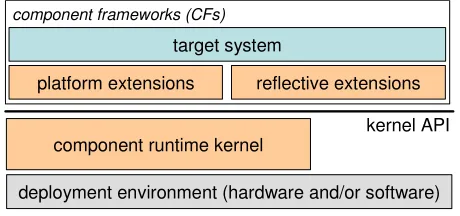
We approach the satisfaction of the requirements identified above—i.e. target domain independence, deployment environment independence, and negligible overhead—through the architecture illustrated in figure 1. At the heart of the architecture is a minimal component runtimekernel that supports the basic services of loading
and binding components. This is discussed in detail in section 3. A runtime kernel is required to be able to support dynamic systems which have an inherent need for runtime reconfigurability (e.g. extensible OSs, active networking nodes, adaptive middleware etc. [Blair,04]). The kernel lies immediately above the (hardware and/or software)
deployment environment. The kernel is policy free, and its application programmer’s interface (API) is target-system and deployment-environment independent. For static target-systems, it is used only to initially configure the system—when configuration is complete, it can be unloaded so that it does not consume any resources. In dynamic systems, the kernel continues to exist at run time. However, even here its resource demands are minimal as shown in section 6.
Above the kernel is a layer of so-called extensions which enhance the basic loading and binding based programming model in accordance with the needs of various target domains and deployment environments. This layer thus plays a central role in providing the tailorability and extensibility that OpenCom aims to deliver. The extensions are independently and optionally deployable and configurable (via the kernel). Importantly, the extensions are themselves implemented as components, so there is no essential boundary between the extensions and target system ‘layers’ and thus no inherent layering overhead. The extensions that we currently employ fall into the two main classes: First, platform extensions, discussed in section 4, provide structured support for tailorability and extensibility at the deployment environment level—essentially, this layer addresses the above-mentioned requirement to efficiently expose unique features of deployment environments in terms of generic component-based abstractions. Second, reflective extensions, discussed in section 5, provide generic support for target system reconfiguration—i.e. inspecting, adapting and extending the structure and behaviour of dynamic systems at run time [Maes,87]. These reflective extensions build on and extend inherently reflective features of the kernel such as explicitly represented cross-component bindings and support for extensible meta-data (see section 3). We also provide a set of security extensions; these, however, are not as mature as the other extensions and are not discussed further in this paper.
platform extensions
component runtime kernel
deployment environment (hardware and/or software) target system
kernel API reflective extensions
[image:3.595.187.417.456.564.2]component frameworks (CFs)
Fig. 1: Overall OpenCom architecture
A key architectural feature of the OpenCom approach is its extensive use of the notion of component frameworks [Szyperski,98]. Component frameworks work at a coarser granularity than components, and contribute a generic approach to the structuring and extensibility of software through component composition. In OpenCom, a component framework (hereafter CF) is a tightly-coupled set of components that i) cooperates to address some focused area of concern; ii) provides a well-defined extension protocol that accepts additional ‘plug-in’ components that modify or extend the CF’s behaviour; and iii) constrains [Clarke,01] how these plug-ins may be organised. As an example, we have a protocol stacking CF that accepts protocol components as its plug-ins, and constrains its plug-ins to be composed into linear stacks [Coulson,02].
component that exports an operation that accepts plug-in components as its arguments. Internally, this root component discovers the interfaces supported by plug-ins (using reflection as explained later), and configures and binds them in a manner appropriate to the CF (e.g. in the above-mentioned protocol stacking CF, the root component would discover and bind the interfaces of its plug-ins to generate a linear stack topology). We have also explored a more sophisticated approach in which CF constraints are expressed at design time in terms of an architecture description language (specifically, ACME [Garlan,00]) and are compiled to generate CF-specific constraint policing code [Joolia,05]. The key point, however, is that different CFs can adopt different approaches to pluggability and constraint. If fact, CFs do not inherently require anything beyond the facilities provided by the foundational component model; i.e. minimal CFs can be viewed simply as architectural patterns.
As will become clear in the remainder of this paper, CFs provide structure and extensibility at all levels of the architecture. At the level of the platform extensions, CFs are provided that, for example, support plug-in ‘loader’ and ‘binder’ components. Similarly, at the level of the reflective extensions, plug-ins take the form of, e.g., operation interceptors. At the target-system level, plug-ins are applied in such areas as protocol stacking (as discussed above), thread scheduling, packet forwarding, memory management, or user interaction; and they define plug-ins and constraints that make sense in those domains.
3. The Programming Model and the Kernel API
3.1 Programming Model
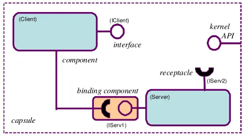
A high-level view of the elements of the OpenCom component-based programming model is given in figure 2 (the legends in brackets refer to the example given in section 3.3 below). Capsules are containing entities into which components are loaded, instantiated and composed. Each capsule defines a name space for its contained component instances (hereafter, we refer to component instances simply as ‘components’), and offers the OpenCom kernel API which is discussed in section 3.2 below. Capsules do not recognise any nesting or hierarchical organisation of their contained components, although such organisations can be conceptually superimposed on this basic ‘flat’ organisation through the use of ADL-based CFs or other such formalisms.
Components are encapsulated units of functionality which interact with other components in their containing capsule exclusively through so-called interaction points, of which there are two types: ‘interfaces’ and ‘receptacles’. Component types are templates from which components (instances) can be instantiated at run time. Each component type is defined by a name, the set of the interaction points it supports, and a set of statically-defined <name, type, value> properties (this so-called ‘static property’ facility is used to associate arbitrary meta-data with a component type which is available at run time using the getprop() kernel call; see below). Interfaces are units of service provision offered by components. Components types may support any number of interfaces including zero (in figure 2, each of the large components has one interface and one receptacle; and the small component has none). The use of multiple interfaces is useful in embodying separations of concern (e.g. between base functionality and component management). Interfaces are defined in terms of sets of operation signatures and associated datatypes. Receptacles are ‘required interfaces’ that make explicit the dependencies of a component on other components. Components may support any number of receptacles. Receptacles are key to supporting the
third-party mode of deployment and composition inherent in a component-oriented environment: when third-party-deploying a component into a capsule, one knows by looking at its receptacles precisely which other components must be present to satisfy the component’s dependencies.
For language independence, we use the OMG’s IDL interface definition language [OMG,95] to define interfaces, receptacles and component types. Interfaces and receptacles are expressed using the standard interface definition syntax1. Component types, on the other hand, employ the following extended syntax (which is similar to a subset of the OMG ‘component’ syntax):
<comp_type_defn> ::= “componentType” <comp_name> “{” <static_props> <provides_and_uses> “}” <static_props> ::= (<prop_name> “:” <prop_type> “=” <prop_value> “;”)*
<provides_and_uses> ::= (<provides> | <uses>)* <provides> ::= “provides” <interface_name> “;” <uses> ::= “uses” <interface_name> “;”
The ‘provides’ clause refers to interfaces supported by the component type and the ‘uses’ clause refers to its receptacles. The elements <comp_name>, and <interface_name> are strings; the latterrefers to the names of IDL interfaces defined elsewhere. Similarly, <prop_name> is a string, and <prop_type> refers to an IDL data type defined elsewhere; <prop_value> is a value of the appropriate <prop_type>.
Note that we do not provide any facilities at the component type definition level for ‘nesting’ component definitions, or to specify static bindings between receptacles and interfaces. The aim is to maximise the simplicity of the programming model. Nevertheless, such higher-level facilities can be straightforwardly built on top where required. For example, we have employed the ACME ADL to specify such concerns, and have also experimented with an XML-based formalism [Joolia,05]. However, when such formalisms are employed they always compile down to the basic OpenCom programming model—i.e. a ‘flat’ component structure in which all receptacle-interface bindings are created at run time.
A binding is a run-time association between a single interface and a single receptacle. Interfaces may participate in multiple bindings, whereas each receptacle may only participate in a single binding at a time. Like component deployment, the creation of bindings is inherently third-party in nature. That is, bindings can be created by any component within the capsule, not only by the ‘first-party’ components whose interface or receptacle is actually participating in the binding. Each binding is represented by a component (the small component in figure 2) that is implicitly created by the kernel. The semantics of these components (often called ‘binding components’) are identical to those of any other component—with the following exception: when such a component is destroyed, the interface/receptacle association that it represents is also destroyed. The OpenCom specification allows kernel implementations to employ binding components that themselves support any number of interfaces and receptacles. Binding components with zero interfaces/receptacles (such as the one shown in the figure) are sufficient for lightweight implementations in resource-poor deployment environment; but less constrained implementations are free to support binding components that have interfaces that, for example, support operations to obtain the identifiers of the bound interface/receptacle, or to insert interceptors. Such facilities, however, are more typically supported by extension binders as discussed in section 4.2.
kernel API interface
receptacle component
binding component
capsule
(Client)
(Server) (IClient)
(IServ1)
[image:5.595.181.421.371.507.2](IServ2)
Fig. 2: Elements of the kernel-level programming model
3.2 The Run Time Kernel API
Each capsule embodies a single kernel instance which offers the following run time API1: interface Kernel {
typedef struct template {long id}; typedef struct component {long id}; typedef struct interface {long id}; typedef struct receptacle {long id};
status load(in string component_type_name, out template t); status instantiate(in template t, out component c);
status unload(in template t); status destroy(in component c);
status bind(in interface i, in receptacle r, out component binding); status putprop(in long entity_UID, in string key, in any value);
status getprop(in long entity_UID, in string key, out any value); long register(in long proposed_UID);
status notify(in ICallback callback); }
This API is deliberately minimal in nature and has been specified on the basis of considerable experience and experimentation with runtime component model APIs over the past few years [Clarke,01], [Coulson,03], [Grace,05]. The basic philosophy is to build the API in terms of two very primitive system-level facilities: dynamic loading (in the shape of load(), instantiate(), unload() and destroy()); and dynamic linking (in the shape of
bind())1. This API then supports the implementation of all other areas of systems-related functionality (e.g. concurrency, protection, distribution, etc.) as well-defined components that build on the basic kernel-level loading and linking services. The fact that the ‘loading and binding layer’ is offered as a well-defined component model which is consistently re-used in the higher layers lends great coherence, uniformity and flexibility to the approach, while at the same time allowing the kernel to be implemented in an extremely small, efficient and policy-free manner.
We now discuss the API in detail. The struct definitions are used to name the four types of entities comprehended by the kernel (i.e. templates, components, interfaces and receptacles). Wrapping the UIDs of these entities in structs facilitates language-independent type safety at a cost of only sizeof(long) bytes of memory overhead per UID. Load() loads a named component type into the capsule and returns a ‘template’—i.e. an in-memory representation of a component type (including its executable code) which can subsequently be instantiated using instantiate(). Instantiation is separated from loading to assist the user in controlling the trade-off between memory economy and instantiation latency. For example, a programmer may choose to load and instantiate on demand (high instantiation latency, but with the benefit of only incurring memory overhead when a given component is actually required); or alternatively she may choose to pre-load templates so that instances can later be created quickly (low instantiation latency at the expense of having the templates occupy memory between the load and instantiate steps). Unload() unloads the specified template (to free up memory), and destroy() destroys a component instance. Unload() fails if there are extant instances of the target template; and destroy() fails if any of the target component’s receptacles or interfaces are currently bound. As the kernel itself is modeled as a component which exports its API as an OpenCom interface, destroy() can be used to remove the kernel itself—this frees up the memory used by the kernel but leaves all components and bindings untouched; the effect is to forego the possibility of making subsequent run-time changes in the capsule. Bind() is used to create a binding between a specified receptacle and interface. As bindings are represented by components, destroy() is used to remove a binding. The arguments to bind() (i.e. an interface and a receptacle of the to-be-bound components) can be obtained from an internal kernel ‘registry’ which is accessed via the putprop() and getprop() calls. All components are required on instantiation to call putprop() to store in the registry their interfaces and receptacles, using built-in
key arguments of “I” and “R” respectively. These interfaces and receptacles can then be retrieved, given the target component’s identifier, using getprop(). Apart from these built-in keys, higher-level CFs and extensions can use the registry facility to attach arbitrary meta-data (using keys that they themselves define) to any component model entity (i.e. templates, components, interfaces or receptacles).
Finally, the purpose of register() and notify() is to provide specific support to the extensions, as discussed below in sections 4 and 5. Register() allocates a UID for any newly-created entity and stores it in the registry. It is used when entities are created by platform extensions rather than by the kernel itself. The role of notify() is to assist reflective extensions in obtaining and maintaining information about relevant activity in the capsule, and to serve as the basis of a policy enforcement point for security and consistency management purposes. When a callback is registered with notify(), every subsequent call on the kernel (i.e. of load(), bind() etc.) is reported to the callback. More specifically, the callback is invoked twice for each kernel call: The first invocation is made before the associated kernel call has been made; it reports the ‘in’ arguments of the kernel call (e.g. the name argument to
load()). The second callback is made after the associated kernel call has been made; it reports the ‘out’ argument values that have come back from the kernel call. It is possible to use this callback facility to ‘veto’ a kernel call by returning a specific value from the first callback. This prevents the kernel call from being executed and as a consequence prevents the second callback from occurring; an error code is returned to the caller of the kernel call.
Despite its minimality and relative ease of realisation (see section 6), the above-described API already provides a powerful and self-contained component-based programming model. It is nevertheless still quite limited in terms of its tailorability and extensibility. For example, it supports only a single (implicit) mechanism for loading and binding components, and it does not provide any specific support for principled reconfiguration beyond the basic capability to dynamically create and destroy components and bindings. The extensions layer described in sections 4 and 5 build on the basic kernel functionality to specifically address such concerns.
3.3 Programming Language Bindings
We have realised the above-described programming model and kernel in Java, C and C++, and in a range of deployment environments (see the case studies in section 7). All the language bindings employ an IDL compiler to generate glue code, and to define, according to standard OMG-defined programming language mappings, the language-specific representations of the four OpenCom entities (i.e. templates, components, interfaces and receptacles), and common data types like ints, strings etc.
Due to its simplicity and accessibility, it is most useful to use the Java programming language to exemplify language binding issues. In the Java binding, components and receptacles are represented as Java classes, and component interfaces are represented as Java interfaces that the component class ‘implements’. The IDL compiler generates the receptacle classes and also a per-component class called _<component_name> from which the programmer’s component implementation class should inherit. This generated class makes available the kernel API operations to its user-defined child class (this is done by transparently pre-binding a per-component receptacle called kernel to the kernel interface), encapsulates the declaration and initialisation of the receptacle classes, and uses putprop() to register the component type’s static properties with the kernel. The child class itself may also, of course, register any further ‘dynamic’ properties with the kernel as it sees fit.
Given this preamble, it should be straightforward to understand the following simple example which refers to the component topology shown in figure 2. First, we define the interfaces used in the example:
interface IServ1 {int op1(int i, int j);} interface IServ2 {int op2(int i);}
interface IClient {int setup(); int call(char op, int arg1, int arg2);}
Next, we define the two component types: the Server type provides an IServ1 interface and has a receptacle for
IServ2; and the Client type provides IClient and has a receptacle for IServ1:
componentType Server {version:int=1; provides IServ1; uses IServ2;} componentType Client {provides IClient; uses IServ1;}
Next, we write Java application code corresponding to these specifications. This might appear as follows:
public class Server extends _Server implements IServ1 { public Server() { super(); }
public int op1(int a, int b) {return ...;} /* defined in IServ1 */ }
public class Client extends _Client implements IClient { public Binding b;
public Client() { super(); }
public int setup() { /* defined in IClient */ Template t_serv = kernel.load("Server");
Component serv = kernel.instantiate(t_serv.id);
OCM_IRefList ilist = (OCM_IRefList)kernel.getprop(serv.id, “I”); IServ1 i_IServ1 = (IServ1)ilist.getIRef("IServ1");
kernel.bind(r_IServ1.id, i_IServ1.id, b); /* binding component returned as b */ }
public int call(char op, int arg1, int arg2) { /* defined in IClient */ ...
int result = r_IServ1.op1(arg1, arg2); /* call the bound receptacle */ return result;
Client loads, instantiates and (first-party1) binds to Server when its IClient.setup() operation is called. It subsequently calls Server.IServ1.op1() when its IClient.call() operation is called.
Much of the machinery is defined behind the scenes in the automatically-generated _Server and _Client
classes. This includes the definition of the receptacle classes (which are conventionally named as
r_<interface_name>—i.e. Client.r_IServ1 in our example) and the initialisation of these in the constructor. The constructor also includes generated code that stores the component type’s static properties into the kernel, together with the component’s interfaces and receptacles (using the ‘standard’ “I” and “R” keys mentioned above). The mirror-image of this latter mechanism, together with a helper class called OCM_IRefList, is employed to obtain the
IServ1 interface from the newly-instantiated Server component. Then bind() is called to bind the Client’s r_IServ1
receptacle to the just-obtained i_IServ1 interface. The kernel type-checks the arguments passed to bind() using Java reflection.
The C and C++ language bindings follow a similar pattern, but suitably adapted to the target language’s capabilities. For example, in the C binding, a component is represented by a .c file that contains implementations of all the component’s interfaces’ operations. The user must also provide startup() and shutdown() lifecycle-management functions, and take responsibility for allocating and deallocating within them the memory for receptacles and interface etc. The IDL compiler generates a per-component header file that contains the necessary definitions of receptacles and interfaces. These are represented as structs, with pointer-to-function members representing operations, and a per-type unique identifier (UID) member to help with type checking (the latter is used by the kernel to type-check the receptacle and interface arguments passed to bind()). The action of bind() is simply to assign the function pointers in the interface struct to those in the receptacle struct, resulting in an extremely minimal and efficient implementation of component binding. Interface operations are represented as user-provided C functions which conventionally take as their first argument the UID of the component instance being invoked. Operation invocations on bound receptacles are realised using per-operation IDL-compiler-generated CALL_<opname>(<receptacle>, <arglist>) macros which transparently dereference the given receptacle to determine and call the appropriate target C function with the appropriate first argument.
4. The Platform Extensions
4.1 Overview
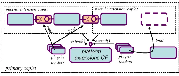
The platform extensions augment the basic programming model elements discussed above with new, optional, abstractions and services that play a major role in delivering the tailorability and extensibility promised by OpenCom. The platform extensions are of three kinds, caplets, loaders, and binders, and they are collectively supported by a CF called the Platform Extensions CF. Figure 3 visualises caplets, loader and binders as being ‘plugged into’ the platform extensions CF using an extend() operation (see later).
primary caplet
plug-in extension caplet plug-in extension caplet
platform extensions CF
platform extensions CF
platform extensions CF
extend() extend() load
b ind
bind
plug-in loaders plug-in
[image:8.595.151.452.486.615.2]binders
Fig. 3: The programming model extended with caplets, loaders and binders
In brief, caplets are specialised plug-in component-support environments that can be dynamically instantiated within a capsule; loaders are plug-ins that are responsible for loading components into caplets in various different ways; and binders are plug-ins that are responsible for creating bindings both within and across a capsule’s caplets in various different ways. In the context of the Platform Extensions CF, the ‘original’ capsule environment (i.e.,
before the Platform Extensions CF was loaded) is referred to as the primary caplet, and all subsequently-loaded caplets are referred to as extension caplets. Similarly, the ‘original’ loader and binder (which are implicit behind the kernel’s load() and bind() calls) are referred to respectively as the primary loader and the primary binder, and all subsequently-loaded ones are known as extensionloaders and extension binders. We motivate plug-in caplets, loaders and binders, and discuss them in detail, in section 4.3 below.
As well as hosting these plug-ins, the Platform Extensions CF recognises and embodies an implicit system development methodology that draws a clean distinction between two distinct ‘programmer roles’ as follows:
• the deployment environment programmer (hereafter environment programmer) creates suitable caplets, loaders and binders for a particular deployment environment using facilities native to that environment (this relates to the pink areas in figures 2, 3 and 4);
• the target system programmer (hereafter system programmer) then develops target systems using the
APIs described in sections 3 and 4.2, together with a specific palette of caplets, loaders and binders that has been provided by the environment programmer (this relates to the blue areas in figures 2, 3 and 4). Distinguishing these two roles is key to OpenCom’s approach of offering a simple and generic programming model in a diverse and extensible environment of target domains and deployment environments. The use of the two roles is discussed in section 4.4; they are further discussed in the context of case studies in section 7.
4.2 The Platform Extensions CF’s API
The API offered by the Platform Extensions CF is as follows: interface Platform_Extensions {
status extend(in extension_type ext_type,
in string ext_name, out component ext); status load(in string name, in component loader,
in component caplet, out template t); status instantiate(in template t, out component c); status unload(in template t);
status destroy(in component c);
status bind(in interface i, in receptacle r,
in component binder, out component binding);
status setdefaultextension(in extension_type ext_type, in component ext); status notify(in ICallback callback);
}
It will first be observed that the API is similar to, but builds on, the basic kernel API given in section 3.
Extend() calls on the primary loader to load and instantiate a component that will play the role of an extension. The
ext_type argument is an enumerated type {CAPLET, LOADER, BINDER} which specifies which one of the three possible extension types is intended; the ext_name argument then refers to the name of a component type that will play the corresponding role (i.e. the role of a caplet, a loader or a binder). Load() is like the similarly-named operation in the kernel API; the difference is that this version allows a particular loader and caplet to be specified. Likewise, bind() allows the specification of a particular binder. Every time a component model element (i.e. a template, component, interface or receptacle) is created, the creating component must record appropriate registry entries pertaining to the element using kernel.register() and kernel.putprop() (e.g. a loader that creates a new component instance should register the latter and the latter’s interaction points). This gives newly-created entities a UID and makes them visible to the rest of the system as if they were created as a result of calls on the kernel API.
Finally, notify() is identical in function to the similarly-named operation in the kernel API. Its use is discussed in section 5.
4.3 Caplets, Loaders and Binders
4.3.1 Caplets
Motivation As mentioned, caplets are specialised component-support environments that can be dynamically instantiated within a capsule. There are three main motivations for caplets. The first is for different caplets to represent different technology domains in the underlying deployment environment. For example, if it was desired to build a system that comprised both C++ and Java components, this could be achieved by employing a separate caplet for each of the two language environments. In such cases, the caplets might typically be realised as OS processes, with one executing a Java Virtual Machine (JVM). Alternatively, if a deployment environment consisted of multiple bus-connected microcontrollers, each with its own private memory, a caplet could be used to represent each microcontroller/memory pair. The essential difference between supporting multiple caplets in the same capsule and simply employing multiple separate capsules is that in the former case all the contained components, regardless of which caplet they are in, see a common name space and a single kernel API instance. This enables the ‘third-party’ loading and binding semantic of the kernel to operate transparently across caplets.
The second motivation for caplets is to provide privacy and isolation between components that are mutually distrustful, or which have different privileges. For example, when building an OS environment one might implement the OS kernel as one caplet and user space as another (or user space could be represented using multiple caplets, one per process; or caplets could be used to impose protection domains in a single address space). A similar strategy could be adopted in an active networking environment where it was necessary to isolate user-provided functionality from system functionality so that the latter could not crash the former (see, e.g., [Karlin,01]). To manage privacy and isolation, extension caplets can choose whether or not to allow their components access to the kernel: Where required, extension caplets arrange kernel access for their hosted components by providing a kernel proxy, and using a cross-caplet binder to bind this to the kernel interface in the primary caplet. But this arrangement can be selectively disallowed either by the primary caplet or by the extension caplet itself.
The third and final motivation for caplets is to support heterogeneous component styles—i.e. different implementations of the abstract component concept. The component style supported by the primary caplet is known as the primary component style; styles supported by extension caplets are known as extension component styles. While the semantics of all component styles must conform to the general characteristics given in section 3 (i.e. support for interfaces and receptacles etc.), each extension component style is free to take its own position on a range of issues such as the following:
• the layout of components on disc and in memory—this may be language/compiler/OS specific;
• whether components can be instantiated multiple times or are singletons (i.e. instantiable only once); • whether components may support an arbitrary set of interaction points or if these are somehow
constrained (e.g. in terms of numbers or types of interfaces, or numbers or types of operations in those interfaces);
• whether components support fixed sets of interaction points or if these can be dynamically created; • whether components are represented as native executables or as interpreted code (e.g. Java).
There are two major reasons to support extension component styles. The first is to be able to accommodate components written using existing component models (e.g. for purposes of reuse, integration, or backward compatibility). For example, we could integrate Microsoft COM components and JavaBeans in a single system by providing a caplet for each of these component styles, together with a suitable cross-caplet binder. The second reason for supporting extension component styles is to support ‘specialised’ styles. For example, in a primitive resource-poor deployment environment such as a microcontroller or sensor network element, we could define a minimal component style that imposed severe restrictions on the numbers of interfaces components can support, or the types of arguments that can be passed to operations (e.g. integers only). Nevertheless, such specialised styles still look exactly the same to external third-party code that deploys and binds components in the standard manner supported by the enclosing capsule’s kernel API. See section 7.2 for a detailed discussion of such a case.
component encapsulates all the deployment-environment-specific machinery needed to realise its particular instantiation of the caplet concept. The necessary machinery is created and/or initialised when the ‘caplet component’ is first instantiated (more detail is given below in section 4.4.1). At the environment programmer level, however, there is a basic requirement that caplets must provide a basic communicational facility to enable them to interact with the rest of the deployment environment (e.g. so that loader and binders can work with them). To meet this requirement the primary style component that represents a caplet must implement the following interface:
interface Caplet {
int createchannel(void);
status destroychannel(in long channel);
status sendmessage(in long channel, in any message); any receivemessage(in long channel);
}
In other words, this interface is required for a component to be recognised as a valid caplet by the Platform Extensions CF. The fact that caplets provide an execution environment for components but are otherwise passive is reflected in the form of this interface which, as can be seen, provides only generic message passing services and does not support any caplet-specific functionality. The way in which these message passing services are used by loaders and binders that will be associated with the caplet is discussed below in section 4.4.1.
4.3.2 Loaders
Motivation Extension loaders are used to load components into a capsule (or, more specifically, a caplet) in some particular manner. In many cases, extension loaders are closely associated with particular caplet types. For example, a caplet type that supports a particular component style would typically have an associated loader that knows how to load and instantiate components of this style. However, the concept of pluggable loaders has a much wider applicability than this. In particular, separating the loader and caplet concepts allows one to associate several loaders with a particular caplet type, or to share common loaders across multiple caplet types. It also allows us to provide different loaders with specialised semantics and behaviours. For example, different loaders might get component templates from different places (e.g. from different repositories or over the network). Similarly, loaders might perform security checks on the templates they load and/or instantiate, or validate particular properties, or perform special behaviours on loading/instantiation. As an example of the latter, a loader might use reflection (see section 5) to transparently analyse a component’s receptacles when loading it, and then recursively pre-load the full set of components on which it depends; or another loader could load balance across a set of processor/memory units managed within a single caplet.
Realisation As with caplets, a plug-in loader is, to the system programmer, simply a primary-style component that offers a facade that hides arbitrary deployment-environment-specific functionality. To be recognised as a loader by the Platform Extensions CF, loader components are required to implement the following interface, the operations of which are called by the Platform Extensions CF as a result of prior calls of the latter’s corresponding calls:
interface Loader {
status load(in string name, in component caplet, out template t); status instantiate(in template t, out component c);
status unload(in template t); status destroy(in component c); }
4.3.3 Binders
Motivation The motivation for plug-in binders is to represent different ‘binding mechanisms’ in the underlying deployment environment. For example, different binders can abstract over binding mechanisms such as interrupts, traps, special buses, shared RAM, optimised register transfers, nearest-neighbour registers in pipeline architectures, or OS-level IPC calls. The plug-in binder abstraction makes all such features uniformly available to the component programmer both within and across caplets, and between components of a common style or different styles. In addition, binders can support special behaviours such as operation interception, performing security checks on invocations, or supporting ‘actor’ like concurrency models in which thread context switches take place while a thread is executing inside a binding.
that assume different calling conventions (perhaps because they were generated by different compilers), or which employ different representations of types or different language semantics. In some cases, these stubs and skeletons may be automatically generated by an IDL compiler in the classic ‘middleware’ style; in other cases they might be hand coded for performance reasons. In all cases, however, the necessary complexity is completely encapsulated within the specific binder and is thus hidden from the user of the generic component-based programming model.
Note that the possibility of cross-caplet binding raises questions concerning the degree of coupling and the distribution of the caplets that comprise a single capsule. The answers are deployment environment specific, but all bindings within an OpenCom capsule are at minimum assumed to be reliable in the sense that the semantic of making a call over a cross-caplet binding should be indistinguishable, apart from a slightly greater latency, from that of making a call over an intra-caplet binding. That is, the binding must not drop or reorder any messages. Given this, one would not usually expect the degree of coupling and distribution within a capsule to be so loose and widely-distributed that cross-caplet binders would need to implement complex middleware-like functionality in order to maintain the required degree of reliability. If a target system must operate in such a loose and widely-distributed environment, the preferred approach would be to design the system not as a set of caplets within a single capsule, but as a number of capsules containing middleware-like CFs (as described in the case study of section 7.3).
Realisation Like caplets and loaders, plug-in binders are simply primary-style components that offer a facade that hides arbitrary deployment-environment-specific functionality. To be recognised by the Platform Extensions CF they are required to implement the following interface:
interface Binder {
status bind(in interface i, in receptacle r, out component binding); status destroy(in component binding);
}
4.4 Programmer Roles
4.4.1 The Environment Programmer Role: Creating Platform Extensions
As mentioned, the Platform Extensions CF sees plug-in caplets, loaders and binders simply as primary style components that support specified interfaces. Behind these interfaces, however, can lurk a great deal of deployment-environment-specific complexity that the environment programmer (but not the system programmer ) must deal with. For example, consider a ‘Java caplet’ that encapsulates a JVM and supports a Java-based OpenCom component style. Having been instantiated with a call of extend(), such a caplet might proceed by forking a new process to run a JVM, and then establish contact with this new process using some OS-specific IPC mechanism—e.g. a UNIX pipe.
primary caplet
plug-in extension caplet plug-in extension caplet
platform extensions
...
...
stub skeleton
cross-caplet binding implementation
delegators go here delegates
[image:12.595.153.451.485.613.2]caplet channels
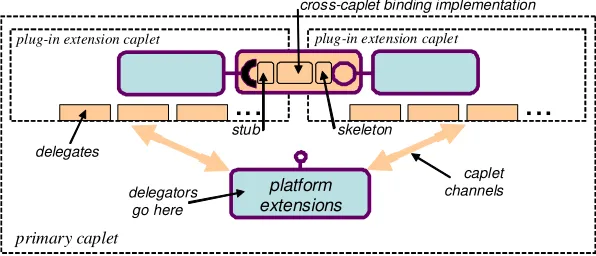
Fig. 4: Environment programmer concepts
programmer concepts of stubs, skeletons and cross-caplet binding implementations—these are dynamically created by plug-in binders as required.)
As a more concrete example of the use of the delegator-delegate pattern, consider the following sequence of steps that might be taken in instantiating a new loader for the above-mentioned Java caplet example:
i) in the primary caplet, the loader component (delegator) is loaded using extend();
ii) this delegator opens a channel to the Java caplet using createchannel() inthe Java caplet’s interface;
iii) the delegator uses a Java-caplet-specific protocol to send (using sendmessage()) a command to the Java caplet delegate to ask it to load the loader’s delegate (loading the loader’s delegate can be done using any appropriate means; as we are in the environment programmer domain here, this is outside the scope of the OpenCom programming model);
iv) the delegator opens a new channel and uses this to communicate, using a loader-specific protocol, with its newly-established delegate.
One would use similar steps to instantiate a binder plug-in for the Java caplet. Cross-caplet binders employ a single delegator and multiple delegates—one in each of the caplets it knows how to deal with. We consider more concrete examples of delegator-delegate based extensions in section 7.2.
4.4.2 The System Programmer Role: Using Platform Extensions
To further appreciate the distinction between the environment and system programmer roles, consider the simple program below in which an system programmer builds on a set of platform extensions that have been provided by an environment programmer. In this program, the system programmer instantiates and third-party binds a primary-style component in the primary caplet to a component in the ‘Java caplet’ discussed above. The system programmer also employs an extension loader that loads components into the Java caplet (as discussed above), and an environment programmer provided extension binder that binds components across the two caplet types.
template jtemp, ptemp;
component jcaplet, jloader, cbinder, jcomp, pcomp, binding; interface ifaces[N];
receptacle recpts[N];
/* set up the Java caplet with a Java specific loader and binder */ extend(CAPLET, “MyJavaCaplet”, jcaplet);
extend(LOADER, “MyJavaLoader”, jloader);
extend(BINDER, “MyJavaToPrimaryBinder”, cbinder);
/* load and instantiate the components */ load(“PrimaryComp1”, PRIMARY, PRIMARY, ptemp); load(“JavaComp1”, jloader, jcaplet, jtemp); instantiate(ptemp, pcomp);
instantiate(jtemp, jcomp);
/* obtain interaction points on the components and bind them */ getprop(pcomp.id, “R”, recpts);
getprop(jcomp.id, “I”, ifaces);
bind(ifaces[0], recpts[0], cbinder, binding);
5. The Reflective Extensions
5.1 Overview
The purpose of the OpenCom reflective extensions is to support the construction of dynamic target systems that need to change or evolve during their execution in a controlled and principled manner. To achieve this, the reflective extensions provide generic support for inspecting, adapting and extending the structure and behaviour of systems at run time. They also help to maintain an architectural separation of concerns between system building (or ‘base-level’ programming) and system configuration and adaptation (or ‘meta-programming’). This distinction is orthogonal to the distinction between the environment and system programmer roles discussed above.
Following Maes [Maes,87], we view the essence of reflection as enabling the inspection and manipulation of ‘causally-connected meta-models’ of a software system [Maes,87]. Causally-connected meta-models are representations of some aspect of the system under consideration, and they expose a so-called ‘meta-interface’ through which the representation can be inspected and manipulated. ‘Causal connection’ means that i) run-time changes made to a meta-model (effected via its meta-interface) cause corresponding changes to immediately be reflected in the represented system; and ii) changes in the represented system that occur due to some external cause are similarly reflected in the meta-model. A key principle of our approach to reflection support is to provide an
extensibleset of orthogonal meta-models, each of which is optional and can be dynamically loaded when required, and unloaded when no longer required (assuming no dependencies). We have found in our experimentation to date that the meta-models described in the following subsection are particularly useful.
5.2 Example Reflective Meta-models
The Interface Meta-model This provides two related capabilities: i) to dynamically discover (at run time) details of the interaction points of a component in terms of their operation signatures; and ii) to perform ‘dynamic invocations’ on dynamically-discovered interfaces. Together, these capabilities enable components to invoke interfaces which were not known to them at compile time (i.e. they need not support the requisite receptacles). Essentially, these capabilities are similar to Java core reflection except that they work at the OpenCom level and are therefore programming language independent. One possible drawback of the interface meta-model is that its dynamic invocation capability allows one to bypass the architectural structure of an OpenCom system in terms of its explicit bindings. But in some circumstances it is important to support such dynamic behaviour. For example, it is particularly useful in supporting generic functionality such as debugging, component database browsing, or generic bridging (cf. the CORBA dynamic invocation interface or DII [OMG,95]). It is also required to support the architecture and interception meta-models discussed below with the necessary typing information.
In implementation, the interface meta-model is realised as a singleton primary-style component that uses the OpenCom kernel’s getprop() and putprop() APIs to store and obtain the interface types associated with a component, and pointers to IDL definitions of these types in an encapsulated IDL repository. It implements dynamic invocation by offering a generic invoke() API which is modeled on the CORBA DII interface. The arguments to invoke() comprise the target interface and operation, together with a stack of argument values that is built manually by the invoking component on the basis of the run-time IDL type information provided by the meta-model. Internally, the meta-model establishes a binding to the target interface in the normal manner (i.e. using the
bind() call) so that the called component is unaware of the fact that it is being invoked in an unusual manner.
The Architecture Meta-model This represents the topology of the current set of components within a capsule. It is used primarily to achieve coarse-grained topological inspection, adaptation and extension of the structure of a dynamic target system. For example, in a media-streaming scenario, we have used it to dynamically manage the set of media codecs in use when a mobile PDA migrates between fixed and wireless networks [Blair,04]. This involves first inspecting the underlying component topology to locate the codec component, and then adapting/extending the topology to effect corresponding change (e.g. to replace the codec). The meta-model provides a ‘graph-oriented’ API in which components are represented as nodes and bindings as arcs. Inspection is carried out by traversing the graph, and adaptation/extension is achieved by adding or removing nodes or arcs (e.g. adding a node results in the deployment of a new component). An example of the use of the architecture meta-model is given in section 7.2.
information as provided by a notify() callback (see section 3). When the architecture meta-model is used to adapt/extend the system topology (e.g. by adding a node as above), it effects the necessary changes by using appropriate kernel calls to load components, create bindings etc. as required.
The Interception Meta-model This meta-model, which is a version of probably the most widely explored reflective mechanism in general use [Kon,02], exposes the process of invoking an operation in a component’s interface. More specifically, a meta-interface is provided that allows the meta-programmer to insert arbitrary code-elements called interceptors within bindings, such that an interceptor is executed whenever an operation is invoked across the binding (more specifically, either before, or after, or both before and after, the invocation). Such an interceptor might, for example, audit the pattern of invocations and their arguments for debugging purposes, or dispatch invocations to an alternative object instance (‘hooking’), or insert a security or concurrency control check on an invocation. Interception is especially useful in adaptation scenarios; for example, in the above-mentioned media streaming/mobile computing scenario, an interceptor on a low-level protocol component could be used to monitor and detect the conditions under which a codec should be replaced by means of the architecture meta-model. In addition, interception can be used as a basis for dynamic aspect-oriented programming [Bencomo,05].
A commonly-cited disadvantage of interception is that it incurs an inherent performance overhead whether or not an interceptor is actually installed [Coulson,04]. This is because interception typically requires bindings to support a level of indirection. Our realisation of the interception meta-model uses the plug-in binder concept to sidestep this disadvantage. That is, we provide both interception-capable and non-interception-capable binders and select from these according to requirement—i.e., we choose an interception-capable binder only where we are likely to need interception. If we choose wrongly we can straightforwardly recover by destroying the current binding and rebinding using a different binder. An additional advantage of per-binder interception is that we can provide alternative models of interception that use different underlying implementations offering different trade-offs.
5.3 Controlling Access to Reflective Meta-Models
Reflection is a powerful and general technique, and its use should always be constrained to minimise programmer errors. Our approach to providing such constraint is to limit the set of components that can access the reflective meta-models: in particular, access is typically given to CFs but not to their plug-ins. As well as preventing spurious access, this helps ensure that meta-models are accessed only when conditions are ‘safe’; for example, a CF might restrict component replacement via the architecture meta-model to situations in which no invocations are currently being made on interaction points owned by the ‘old’ component. Further, a CF could define a suitable state-transfer protocol to carry-over essential state from the old component to the new one.
6. Performance and Overheads
We now discuss the inherent performance properties and overheads of OpenCom. This section offers a generic treatment; more specific performance evaluations involving measurements of particular systems constructed using the technology are given in section 7.
In assessing inherent overheads, we recognise a key distinction between in-band and out-of-band execution [Coulson,04]. In-band execution refers to segments of code that are repeatedly executed in the normal course of events and are therefore particularly performance sensitive; out-of-band execution, on the other hand, refers to code segments that are executed only ‘occasionally’ to the extent that their impact on system performance is negligible. On the basis of this distinction it can be seen that the kernel inherently incurs zero in-band execution overhead—this is because it is only involved in out-of-band operations, viz. loading, instantiating and destroying components; and creating and destroying bindings. These operations are typically only invoked when a system is being (re)configured; that is, an established component topology need not make any calls on the kernel. Note that this is quite unlike the situation in operating system microkernels, which are unavoidably involved in critical in-band operations (such as interrupt handling or thread scheduling). Note also that the ‘out-of-in-band’ characterisation, with the exception of the overhead introduced by interception-capable binders (see below), also applies to the reflective meta-models.
• overheads inherent in the primary and extension component styles used (e.g. per-component memory overhead)
• performance overheads inherent in bindings (whether created by the primary binder or extension binders) • the granularity of the componentisation of the target system (which, in turn, affects the relative impact of
the above two factors).
To gain insight into these overheads we now provide a brief overview of our ‘reference’ kernel implementation1 and present some basic measures of its performance and overheads2. The reference implementation realises its primary caplet in terms of a standard Linux process (it also runs under Windows). The primary component style is based on the standard ELF executable format emitted by the GNU C++ compiler. The primary loader is based on Linux Shared Objects (or Windows DLLs), and the primary binder uses standard C++ vtables to realise bindings. As well as the primary binder we have two extension binders that work with primary-style components in the primary caplet: the first of these offers an implementation of the interception meta-model; the second optimises away the vtable apparatus by replacing the usual vtable-based indirected call in the caller’s code segment with a simple CALL instruction. While this CALL-based extension binder saves some overhead, it can only be used where the component on the receptacle side is a singleton. Note that the CALL-based binding works by modifying the code associated with the receptacle in the caller’s code segment. Such code rewriting approaches are sometime dangerous; our modification, however, is small, well-defined and constrained in scope.
Using our reference implementation, we carried out the following measurements of inherent overhead, the results of which are summarised in Table 1:
• Memory footprint of kernel. We measured this as 32 Kbytes. This is a modest overhead which should
make the kernel deployable in many resource-scarce environments.
• Memory footprint of a null component. The memory requirement of a null primary-style component (i.e. one with no interfaces and receptacles and null initialisation/finalisation routines) is 36 bytes. This compares to an overhead of 20 bytes for a single null C++ object. In addition, the interface and per-receptacle overhead is 28 bytes (with an additional 5 bytes per operation).
• Component loading and instantiation time. The time taken to load a single null primary-style component
(averaged over a few million loads) was measured as 9.8µs (compared to 7µs for a Linux Shared Object containing a null C++ object); and the time to instantiate an already-loaded null component was measured as 0.47µs (compared to 0.28µs for a null C++ object). The small overheads here are attributable to the larger file size of the OpenCom component template (due to meta-data etc.), and the slightly more complex instantiation process, including interaction with the kernel registry.
[image:16.595.115.468.489.633.2]• Time to create a primary binding. This was measured as 2.4µs—which is identical to the time required to create a vtable in C++.
Table 1: Summary of Measures of Inherent Overhead
OpenCom Native C++
Memory footprint of kernel 32 Kbytes N/A
Memory footprint of null component 36 bytes 20 bytes (null C++ object)
Mem. footprint of receptacle/interface 28 bytes N/A
Component loading time 9.8µs 7µs (null C++ object)
Component instantiation time 0.47µs 0.28µs (null C++ object)
Time to creating a primary binding 2.4µs 2.4µs (C++ vtable creation)
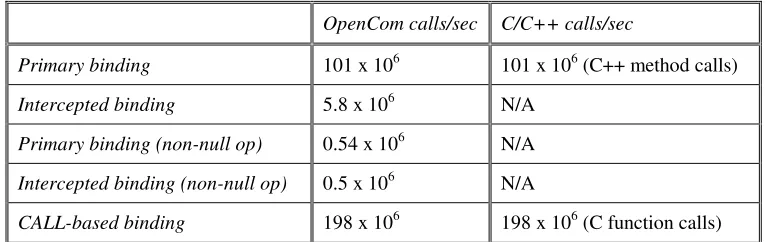
Next, we measured the time taken to perform invocations across different types of bindings. The details, which are summarised in Table 2, are as follows:
1 In addition to our C++-based reference implementation, we have Java and C implementations as discussed in section 3.3.
• Overhead of calls made across a primary binding. To measure this, we performed a series of invocations across a primary binding involving an interface with a single operation with no arguments and a void return value. We measured 101 x 106 calls per second. We then confirmed that, as expected, this is identical to the invocation rate achieved when calling a method in a simple C++ object (which employs vtables in an identical manner). Thus there is zero in-band overhead arising from the use of the primary binder.
• Overhead of calls made across an intercepted binding. This test used the same interface as above but employed a binding created by our interception-capable extension binder. We used a null ‘before’ interceptor and measured 5.8 x 10⁶ calls per second. Comparing this overhead with that of the primary binder (see above), this represents a slowdown factor of 17.4—thus it is clear that there is a substantial cost incurred for interception. However, to put this into perspective, we repeated the comparison using a target operation with a more typical and representative non-null body—viz. an empty loop of 1000 iterations. This time we measured 0.54 x 10⁶ calls per second for the primary binding and 0.5 x 10⁶ for the intercepted binding—a slowdown factor of only 1.08. This illustrates that the absolute overhead of calls in still very small. Bear in mind also that, as explained in section 5, an system programmer only needs to incur this cost when interception is actually required.
[image:17.595.102.487.346.467.2]• Overhead of calls made across a CALL-based binding. This test again used the above-described interface but this time employed our CALL-based singleton binder. We measured 198 x 106 calls per second, thus revealing that singleton bindings yield a two-fold speed-up over primary (vtable-mediated) bindings. We also confirmed that, as expected, this is identical to the performance achieved when calling a null C function in a simple C program. Again, this indicates zero in-band overhead arising from the use of the binder abstraction.
Table 2: Overhead of OpenCom Operation Invocation
OpenCom calls/sec C/C++ calls/sec
Primary binding 101 x 106 101 x 106 (C++ method calls)
Intercepted binding 5.8 x 10⁶ N/A
Primary binding (non-null op) 0.54 x 10⁶ N/A
Intercepted binding (non-null op) 0.5 x 10⁶ N/A
CALL-based binding 198 x 106 198 x 106 (C function calls)
Overall, it can be fairly concluded from the above figures that the basic approach to building component-based systems adds little overhead to that of a traditional programming language based systems development environment.
7. Case Studies
7.1 Overview
Having described and evaluated the basic OpenCom technology, we now report on our experiences with the technology and present two representative and contrasting case studies of the use of the technology to build non-trivial target systems.