Development of a RadFET Linear Array for
Intracavitary in vivo Dosimetry During External
Beam Radiotherapy and Brachytherapy
Robert A. Price*
, Member, IEEE
, Chris Benson, Malcolm J. Joyce, and Kenneth Rodgers
Abstract—We present the details of a new linear array dosimeter consisting of a chain of semiconductors mounted on an ultra-thin (50 m thick) flexible substrate and housed in an intracavitary catheter. The semiconductors, manufactured by NMRC Cork, have not been packaging and incorporate a passivation layer that allows them to be mounted on the substrate using flip-chip-bonding. This paper reports, for the first time, the construction of a multiple (ten) detector array suited to in vivo dosimetry in the rectum, esophagus and vagina during external beam radiotherapy, as well as being adaptable to in vivo dosimetry during brachytherapy and diagnostic radiology.
Index Terms—Dosimetry, in vivo patient dosimetry, MOSFET, RadFET, radiotherapy, semiconductor detectors.
I. INTRODUCTION
T
HE overall process of planning and treatment of a patient with ionizing radiation encompasses many complex and diverse steps, all of which are subject to uncertainty [1] and pos-sible human error. In order to provide efficacious disease man-agement, radiotherapy treatment requires the patient to be ac-curately positioned with respect to the radiation fields so that a therapeutic dose can be delivered to the target region (tumor) whilst the absorbed dose to the normal tissue and organs at risk is kept to a minimum. It is known that the accuracy with which the patient is positioned in the beam affects both the probability of cure (tumor control) and the undesirable complication rate [2]. In addition to the geometric precision with which the pa-tient is positioned, the efficacy of the treatment is critically de-pendent on the magnitude of the absorbed dose in the tumor and other volumes. Using clinically derived dose-effect curves for local tumor-control and normal tissue-complications, var-ious authors have estimated the accuracy requirements for dose delivery in conventional external-beam treatments to be 3.5% for absolute dose at the specification point and 5% at other points within the target volume [3]–[6]. For other, high-pre-cision treatments such as conformal radiotherapy, Essers [7]Manuscript received November 14, 2003; revised April 6, 2004. This work was supported in part under EU framework–V Grant (InvoRad Project): ISD-200125343. The work of C. Benson was supported by Engineering and Physical Science Research Council.Asterisk indicates corresponding author.
*R. A. Price is with Computational and Applied Dosimetry Research Group, Physics Department, Clatterbridge Centre for Oncology NHS Trust, Wirral CH63 4JY, U.K. (e-mail: [email protected]).
C. Benson is with Appleyard Lees, Halifax HX1 2HY, U.K.
M. J. Joyce is with University of Lancaster, Lancaster LA1 4YW, U.K. (e-mail: [email protected]).
K. Rodgers is with NMRC Cork, Cork, Ireland (e-mail: [email protected]). Digital Object Identifier 10.1109/TNS.2004.832570
notes that the accuracy criteria may need to be tightened: cur-rent wisdom stating a 2% or 2 mm criterion on absorbed dose and positional accuracy respectively.
It is apparent that effective quality assurance and control pro-cedures are essential in radiotherapy if the above stated accu-racy is to be achieved and maintained. Within such a quality as-surance program, individual quality control tasks are concerned with checking the accuracy and precision of each step in the planning and delivery chain [8] but it is only at the final step, when a beam is actually delivered to a patient, that a single check on the whole procedure (through in vivo dosimetry measure-ments) can be made and the attainment of a desired dose-accu-racy formally confirmed.
Clearly, patient dose verification at the point of delivery is an important part of quality assurance in radiotherapy treat-ment [9]. It is included as a requiretreat-ment in the UK Manual of Cancer Standards [10] and is recommended within the whole of Europe [11] and North America [12] for procedures involving high doses to the patient. When included as part of a general system of radiotherapy quality assurance within a clinic, in vivo dosimetry can significantly reduce the risk of mistreatment. Two commonly used detectors for in vivo dosimetry are thermolumi-nescence dosimeters (TLDs) and semiconductors.
TLDs are popular because of their small size but they require extremely careful handling and calibration in order to obtain a measurement accuracy of better than 5% at 95% confidence. They are, to some degree, inconvenient to use, as they require specialized ovens for post irradiation annealing and expensive TLD reading equipment. Further, they do not provide a means of ‘real-time’ dosimetry because there must be a well-controlled delay of approximately two hours or more between irradiation and reading in order to allow the decay of short-lived traps. Due to the stringent handling requirements and the need to protect the TLD chips from UV light and chemical contaminants they are not well-suited for inclusion in arrays or for use in intracav-itary dosimetry. Some authors have, however, used TLDs for intracavitary in vivo dosimetry—for example, Brezovich [13],
et al.incorporated some 20 LiF rods in a 6fr urethral catheter
in order to verify high dose rate (HDR) prostrate treatments; the TLD rods being read within 24–48 hrs of the radiation treatment. Semiconductor detectors such as diodes and metal-oxide field-effect transistors [14] (MOSFETs) provide a conve-nient alternative to TLD technology. Such detectors can be constructed with a small active volume whilst retaining high sensitivity and accuracy [15]. Importantly, real-time in vivo dosimetry (using semiconductor detectors, MOSFETs or
monds, etc) allows differences in recorded and expected dose values to be investigated with the patient still in the treatment position [16]. Based on such measurements and an analysis of the actual treatment set-up, a treatment can be modified, if deemed suitable, before the next fraction in order to bring the overall treatment back in-line with expectations. This approach to the use of real-time in vivo dosimetry is discussed by several authors [17], [18] and has been put into practical use by various groups [19]–[21].
The majority of in vivo dosimetric measurements performed in the clinic are achieved by placing the detector on the entrance or exit surface of the patient and the tumor dose derived via various algorithms—for example Leeet al.[22]. However, it is often desirable to make intracavitary measurements of absorbed dose distributions: For example, during external beam treatment of rectal carcinoma the dose delivered to the rectum and the re-gion of the anal verge is of critical importance in controlling deleterious complications [23] and so intracavitary in vivo mea-surements are indicated. Similarly, intracavitary meamea-surements during cervical treatments or head and neck treatments would provide valuable information on the absorbed dose to sensitive structures such as the bladder and esophagus.
In this paper we describe the design and construction of a prototype catheter array based on RadFET (radiation sensitive MOSFETs) and diode detectors—specifically, we describe a prototype rectal array in which the semiconductors do not have equal spacing but this is not a limitation of the system.
II. MATERIALS ANDMETHODS
A. RadFET Detectors
The RadFET detector is a p-type Metal Oxide Field Effect Transistor (p-MOSFET) that has been optimized as a radiation detector [24]–[26]. These detectors have excellent radiation-and physical-characteristics that make them eminently suitable for use as in vivo radiation detectors in radiotherapy applica-tions [27]–[30]. Exposure to ionizing radiation, such as gamma rays, x-rays, electrons and high-energy protons produce a pre-dictable shift in the threshold voltage (proportional to absorbed dose) that is easily measurable with a simple circuit that can be integrated on the same small chip; they can provide real-time accumulated absorbed-dose information and are thus suited to use in Intensity Modulated Radiotherapy (IMRT) applications; as with diodes, they are highly sensitive (approximately 1800 times more sensitive per gamma than an equivalent volume gas-detector) and are small in size (1 ), they can be operated in zero-bias mode and typically show a lower over-response at low-energies than do currently available commercial diodes [31].
The RadFET used in this work is the ESAPMOS4 device manufactured by NMRC Cork. This consists of four RadFET detectors and an integral diode on the same silicon chip. The chip is 1 mm square and houses two (300/50) and two (690/15) devices as well as an on-board diode. The ratios above refer to width/length ratio of the gate oxide region. The on-board diode has a P+ to N+ minimum dis-tance of 15 . There are 12 bond-pads in the chip that are used for making electrical connections. The bond-pad size is 100
square and the distance between bond-pads is 150 . We have used a 400 nm Implanted Gate Oxide RadFET (IMPL RadFET) which, because of additional implantation steps, has a lower initial output voltage than the standard (un-implanted) 400 nm RadFET. The preirradiation output voltage of 400 nm gate, thick oxide IMPL RadFET (300/50) is about 1.5 V, whereas the initial voltage of a standard 400 nm gate, thick oxide RadFET (300/50) is about 8 V. For 690/15 devices the output voltages are approx. 1 V lover than these.
B. Flip-Chip Bonding
In order to obtain the minimum interconnection complexity on an array of ten or more RadFETs we have used a process known as flip-chip bonding [32], [33]. This bonding method has a lower footprint dimension than other interconnection tech-niques, such as wire bonding, and removes the need to have multiple wire bond interconnects that would significantly in-crease the overall dimensions of the array and possibly cause radiation shielding difficulties. Flip-chip interconnection uses conductive bumps to connect the chip to corresponding sub-strate bond-pads. All packaging is removed and the bare chip is flipped upside down in order to make the appropriate connec-tions directly from the chip to the substrate. In this way, it is only the chip dimensions that determine the final footprint.
There are a number of flip-chip techniques that can be used in order to make the bond between the chip and the bond-pads. We have used an anisotropic conductive adhesive to bond the RadFET to the flexible substrate. To perform this mounting technique the bond pads of the RadFETs are first coated with 20 high nickel bumps using an electrolyzes plating technique. We then used Loctite 3441 anisotropically conductive adhesive to achieve the electrical connection to the substrate. This ma-terial consists of electrically conductive particles (5-micron di-ameter gold-coated polymer-spheres) dispersed in an adhesive matrix at a high concentration to ensure reliable conductivity between the substrate and the die i.e. electrical interconnection is in the z-axis direction where particles are trapped between the bump and track and electrical insulation is maintained in the x-y plane of the bond interface. In our mounting technique the chip is bonded under 5 pressure at 200 .
C. Description of the Rectal Array
The array herein described has been constructed specifically for measuring the dose distribution from the location of the tumor to the position of the anal verge during external beam ra-diotherapy treatment of an anal carcinoma. In this construction we have deliberately used nonuniform detector spacing so that we can resolve information in the rapidly changing dose area at the anal verge. All other dimensions of the array have been chosen so that it is suitable for esophageal, rectal and vaginal placement. In future developments the external dimensions will be significantly reduced to permit its use in brachytherapy catheters.
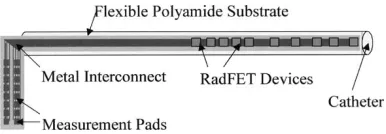
The array is 12.5 cm in length and consists of ten RadFETs placed inside a catheter of overall length 53 cm (Fig. 1).
Fig. 1. Schematic of the rectal array showing the position and spacing of the individual detectors.
Fig. 2. Schematic cross section of the array showing the rolled flexible interconnect. In the rectal array, the RadFETs are positioned close to the surface of the catheter to permit dose measurements at the rectal wall.
at the tumor location. The greatest density of detectors (detec-tors 1–6) are used to monitor the dose in the anal region, these detectors have a spacing of 0.6 cm. The following 6 cm have two detectors (detector 7 & 8) spaced at 3 cm intervals. The final two detectors (detectors 9 & 10) are placed at 11.5 cm and 12.5 cm. The detector array has a diameter less than 0.4 cm so it can be placed in a standard catheter, which is its self filled with tissue equivalent gel. Markers that can be seen on a portal imager or x-ray film are placed between detectors 6 and 7 and detectors 9 and 10 to aid in correct placement on the catheter.
The polyimide interconnect substrate consists of a 50 thick polyimide layer with metal tracks to provide electrical contact to the RadFET devices. The metal tracks are 70 wide with a gap of 70 between each track. They consist of a base metal layer of 5 of copper coated with a 3 layer of nickel and finally a 0.07 layer of gold. In later developments we intend to remove this gold layer to reduce any local dose-enhancement due to photoelectron generation at low energies [34].
Using a 70 track and gap width for the metal tracks and al-lowing for up to 120 tracks to connect out all I/Os of the RadFET devices required a substrate width of 1.7 cm—which is signif-icantly larger than the inner diameter of the catheter. However because the substrate is flexible we have been able to roll it up to allow insertion within the catheter. The cross section of the system is shown schematically in Fig. 2.
Fig. 3 shows the actual prototype constructed array. Clearly seen are the individual RadFET devices and the 70 tracks used for electrical connections.
D. Electronic Read-Out
Throughout the work herein discussed, the change in threshold voltage after irradiation was measured using a PC to control a Keithley Instruments 2400 source-meter via a Hewlett Packard GPIB controller card. The system was configured to measure the gate-source voltage whilst simultaneously passing a fixed channel current of 10 . In order to reduce the influence of short-lived interface states, the reader circuit was programmed to measure the threshold-voltage 10 s after the initial turn-on of supply current to the RadFET.
Fig. 3. Actual prototype array showing the individual RadFETs flip-chip mounted on the flexible substrate and the 70minterconnection lines.
III. RESULTS
Electrical parameters of each RadFET were checked in both the read and irradiation modes just prior to irradiation in order to ensure their correct functionality. RadFETs were irradiated with either 0 V or 5 V present on the gate terminal and all other con-nections grounded. In the later case the applied potential results in a 25 MV/cm field across the gate oxide. This field reduces hole-electron recombination in the and enhances hole-trapping within the oxide, thereby providing a greater threshold-voltage shift and thence sensitivity.
A. Radiation Characterization
Initial characterization focused on four aspects of the individual RadFET performance: 1) Linearity of response with absorbed dose, 2) determination of the energy-dependent sensitivity, 3) evaluation of inherent reproducibility and 4) determination of the lower level of detection. Except for the energy-response analysis, all experimental work was performed on medical linear accelerators with bremsstrahlung spectra having end-point energies of 6 or 10 MeV and dose rates of approximately 6 Gy/min. Data at in a spectrum was obtained on a medical cobalt machine (dose-rate approxi-mately 6 Gy/min at reduced source-detector distance). Energy-response data was obtained using a PANTAK HF-320 constant potential x-ray generator using ISO narrow spectra at the Regional Radiation Protection Physics Service, Birmingham, UK [35].
Device Dose Linearity: In order to measure the linearity of
[image:3.612.94.240.167.236.2]Fig. 4. Average response for 20 RadFET devices as a function of increasing absorbed radiation dose from a 10 MV medical linear accelerator. The solid line is a linear fit to the data. Statisticalr = 0:998.
[image:4.612.302.551.284.467.2]effect on the response of the RadFET but that the measured ab-sorbed dose in this location was statistically identical to that at the location of the RadFET. A calibrated thermometer was sim-ilarly placed within the phantom to provide accurate tempera-ture measurement. The Farmer chamber output was measured using a calibrated Keithley 35 040 therapy electrometer and the absolute value of the absorbed dose to water was subsequently derived through the UK standard high-energy photon dosimetry protocol. Prior to irradiation, the phantom and RadFET were al-lowed to reach thermal equilibrium. Throughout the experimen-tation, the phantom temperature was constant to within 1
Fig. 4 shows the device output (voltage-shift) as a function of total absorbed dose (water) for 5 V biased devices. The data points represent the mean value observed for 20 RadFETs. Each device was subjected to increasing absorbed dose—applied in discrete steps from 0.01 Gy (water) to approximately 50 Gy (water). The Fig. clearly demonstrates a near linear response shows up to 50 Gy (water) with for a linear model.
Interdevice Response Variability: Interdevice variability was
examined, using the same experimental set-up as for the lin-earity tests, for both 0 V and 5 V gate bias, in each case twenty RadFETs were used. Fig. 5 shows the probability distribution of sensitivities ( -shift per Gy) for the case of 0 V bias whilst Fig. 6 shows the distribution for 5 V gate bias. We observed a statistical of 3% at 0 V and 1% at 5 V gate bias respectively. Mean absolute sensitivities are 0.0619 and 0.1414 V/Gy at 0 V and 5 V respectively.
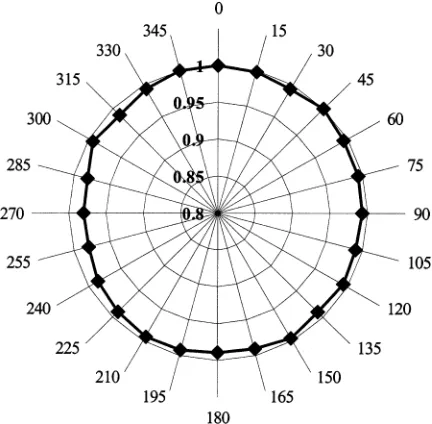
Response Angular Anisotropy: Angular anisotropy was
mea-sured free in-air to avoid changes in optical depth of the device in the parallelepiped phantom as a function of beam angle. Each device was held in a low-scatter arm and irradiated to nomi-nally 0.1 Gy at 15 intervals through 360 . The angle relative to the machine central axis was measured with a digital incli-nometer to better than 1 . A fixed Farmer chamber (calibrated to national standards) provided an independent monitor of the machine output for normalization purposes. Fig. 7 shows the in-air anisotropy plot, the data being the mean response of
5-de-Fig. 5. Interdevice variability in sensitivity at 0 V bias for 20 devices.Mean =
[image:4.612.319.535.517.729.2]0:0619 V=Gy, = 3%.
Fig. 6. Interdevice variability in sensitivity at+5 V gate bias. Twenty devices were irradiated to 0.1 Gy-absorbed dose to water as described in the text. Mean sensitivity is seen to be 0.1414 V/Gy, = 1%.
Fig. 8. RadFET energy response (+5 V bias) measured using a PANTAK HF 320 constant potential x-ray generator and ISO narrow spectra—solid line. Also shown are computed values of the relative energy deposition using MCNPX (triangles). The response is relative to that in a Cospectrum.
vices. All data are normalized to the response at 0 . Uncertainty in the plotted data points is 1% at . Anisotropy is 2.5%. Some distortion is expected due to asymmetric placement of the RadFET in the catheter.
Response Variation With Photon Energy: The energy
re-sponse of the RadFET ( 5 V gate bias) was measured using the three different radiation sources described above. High-energy response data were obtained with the RadFETs mounted 7 cm deep in the PMMA phantom, the actual absorbed dose to water being determined as for the linearity experiments. Low-energy response data were obtained with the RadFETs surface mounted on a thin, ultra low-density expanded polysty-rene block supplied by RRPPS. This block is used to provide structural support with very little backscatter thus changes in the backscatter factor over the energy range of interest had little effect on the total absorbed dose. Further, since the active region is only 400 nm thick and has above it only 1.2 of low Z material, including a silicon nitride passivation region and beneath it approximately 400 of Si, the device essentially sees the surface dose. In all cases, absolute dosimetry was performed by RRPPS and was traceable to national standards.
Fig. 8 shows the observed energy-response at low-energies (solid line and squares). Also seen on the plot are Monte Carlo calculated values of energy-deposition (triangles). All data are relative to the response in a spectrum. Experimental un-certainty is better than 2% at and calculated and experiment results match to better than 2%. The relative responses at 6 and 10 MV (not shown) are 1 and 0.99 respectively. An over-re-sponse of approximately a factor of 6 (relative to ) is ob-served—this is consistent with results on other commercially available devices [31] however, in our case, we observe a second maximum at around 100 keV (both experimentally and compu-tationally). This is currently under investigation by the authors. It is likely to be due to secondary photoelectrons from high-Z materials in the RadFET or substrate construction [36], [37].
B. Monte Carlo Simulated Energy Deposition
In order to quality assure the energy-response data and to pro-vide future modeling for device optimization purposes we have built a detailed Monte Carlo simulation model of the RadFET device using MCNPX [38]. We assume direct proportionality between the energy deposited in the oxide layer and the physical response of the device. Although this is clearly an
approxima-tion—especially at very low energies, it is sufficient for our cur-rent purposes. Calculations proceed, as usual, from the primary source spectrum. In the case of the low-energy response, we have used the defined ISO narrow spectra that have been verified for the RRPS machine used. In the case of the high-energy re-sponse, the exact spectra are not known experimentally. In these cases, we have first computed the mixed photon and electron spectra for the linacs used through detailed Monte Carlo models using [39] and used this spectrum as the primary spectrum for the subsequent coupled photon-electron MCNPX calculations. In all cases we have converged the MCNPX cal-culations to 1% statistical accuracy, although it is understood that this is only a partial component of the overall uncertainty budget for the calculation. In all cases, the energy-deposition tally was used and passed all statistical tests of sampling and convergence provided within the MCNPX code.
IV. DISCUSION
Device Linearity: Measurement of device linearity to
absorbed radiation dose has shown that individual RadFETs follow a sufficiently linear model , at least up to approximately 50 Gy-absorbed dose (water), to allow simple determination of absorbed dose via a single calibration factor. This first-order model becomes increasingly inaccurate at higher levels of absorbed dose when it is more appropriate to use an exponential expression [34].
Angular Anisotropy: In-air studies on bare RadFETs reveals
an angular anisotropy of better than 2.5% over 360 . This is ex-pected to be reduced for the devices encapsulated in the uniform cylindrical catheter. Providing the orientation of the catheter is known to within 90 when positioned in the patient, the uncer-tainty in measured dose due to anisotropy effects will be better than the maximum 2.5% above. Due to the construction of the catheter array, it is unlikely that it will twist by more than a few degrees during insertion, ensuring that the uncertainty due to an-gular anisotropy is better than 2.5% in practice.
Device Sensitivity: Device sensitivity has been shown to be
0.1414 V/Gy when biased at 5 V. In this mode, we are able to measure doses lower than 0.05 Gy (water) based on a signal above noise [40]. This is sufficient to measure doses within the penumbral region of the radiation beam (defined to be approxi-mately 20%–80% of the central axis dose [3] of 2 Gy per frac-tion for a typical external beam treatment) and approximately 0.1 Gy for organs at risk such as the anus, which lie just outside of the beam.
Interdevice Variability: The variability in sensitivity
be-tween devices is important when considering the calibration of a multiple detector array. We have measured this variability to be better than 1% for devices biased at 5 V and 3% when they are used in passive mode indicating that for all but the most stringent requirements, a single calibration factor is sufficient providing that the devices have all been manufactured from the same wafer.
V. CONCLUSION ANDFUTUREWORK
We have developed and constructed a prototype catheter dosimeter based on MOSFET technology that is suited to use within natural cavities of the human body. In particular, we have adapted and utilized an existing MOSFET designed specifically as a radiation detector—the ESAPMOS4 RadFET from NMRC Cork. The radiation response characteristics of individual RadFETs have been shown to be suitable for use as in vivo dosimeters, i.e. they have small size, require zero or low voltage bias, can provide a dose measurement with the patient still in position on the therapy bed and posses dose linearity to therapeutically high dose levels.
We have successfully demonstrated that these devices can be used at absorbed dose levels as low as 0.05 Gy, which is suffi-cient to monitor the dose in regions just outside of the defined radiation field—i.e. at the anal verge in a rectal treatment.
Within the framework of a 3.5% total uncertainty of dose measurement, when used with a simple linear response model the RadFETs used in this work are adequate for single patient use in a QA program incorporating selective in vivo dosimetry. The device presented herein is suitable for on-line in vivo dosimetry for external beam radiotherapy of the rectum, esoph-agus and vagina. As discussed by other authors [41], MOSFET dosimeters have an application in the characterization and quality assurance of the steep dose gradients associated with the penumbra of modern radiation modalities and we have put this to good use in the array presented.
Future work involves a detailed analysis of changes in sensi-tivity with respect to dose-rate, scattered radiation and temper-ature—although the on-board diode will be used in practice for temperature compensation.
A patient based trial of the array dosimeter in the treatment of rectal carcinoma is planned. We are currently in the process of building a dedicated multichannel RadFET reader and ex-tending the concept of the array to the use of other semicon-ductor detectors, such as diodes.
ACKNOWLEDGMENT
R. A. Price would like to thank Clatterbridge Centre for On-cology for continuing research support. The authors would also like to thank the Regional Radiation Protection Physics Service (RRPPS) for making available their low-energy photon calibra-tion facilities.
REFERENCES
[1] Guide to the Expression of Uncertainty in Measurement, International Organization for Standardization (ISO), Geneva, 1995.
[2] J. C. Stroom and B. J. Heijmen, “Geometrical uncertainties, radiotherapy planning margins and the ICRU-62 report,”Radiotherapy Oncology, vol. 64, no. 1, pp. 75–83, July 2002.
[3] W. P. H. Mayles, R. Lake, A. Mcenzie, E. M. Macaulay, H. M. Morgan, T. J. Jordan, and S. K. Powel, Eds., “Physics Aspects of Quality Control in Radiotherapy,”, IPEM Rep. no. 81, 1999.
[4] A. Brahme, “Dosimetric precision requirements in radiation therapy,”
Acta Radiol. Oncol., vol. 23, no. 5, pp. 379–391, 1984.
[5] C. J. Millwater, A. S. Macleod, and D. I. Thwaites, “In vivo semicon-ductor dosimetry as part of routine quality assurance,”Br. J. Radiol., vol. 71, no. 846, pp. 661–668, 1998.
[6] M. Goitein, “Calculation of the uncertainty in the dose delivered during radiation therapy,”Med. Phys., vol. 12, no. 5, pp. 602–612, 1985.
[7] M. Essers and B. J. Mijnheer, “In vivo dosimetry during external photon beam radiotherapy,”Int. J. Radiation Oncology Biol. Phys., vol. 43, no. 2, pp. 245–259, 1999.
[8] J. H. Lanson, M. Essers, G. J. Meijnheer, A. W. H. Minken, G. J. Uiter-waal, and B. J. Mijnheer, “In vivo dosimetry during conformal radio-therapy, requirements for and findings of a routine procedure,” Radio-ther. Oncol., vol. 52, no. 1, pp. 144–151, 1999.
[9] P. Mangili, C. Fiorino, A. Rosso, G. M. Cataneo, R. Parisi, E. Villa, and R. Calandrino, “In vivo dosimetry by diode semiconductors in combi-nation with portal films during TBI: Reporting on a 5-year clinical ex-perience,”Radiother. Oncol., vol. 52, no. 3, pp. 269–276, 1999. [10] Manual of Cancer Standards, UK Department of Health Publication,
2000.
[11] “Health protection of individuals against the dangers of ionising radia-tions in relation to medical exposures,”Official J. Eur. Community, vol. L180/22, 1997.
[12] G. J. Kutcher, L. Coia, M. Gillin, W. F. Hanson, S. Leibel, and R. J. Mortonet al., “Comprehensive QA for radiation oncology report 40 of AAPM radiation therapy committee task group 40,”Med. Phys., vol. 21, no. 4, pp. 581–618, 1994.
[13] I. A. Brezovich, J. Duan, P. N. Pareek, J. Fiveash, and M. Ezekiel, “In vivo urethral dose measurements: a method to verify high dose rate prostate treatments,”Med. Phys., vol. 27, no. 10, pp. 2297–2302, 2000.
[14] Handbook of Radiation Effects, 2nd ed., Oxford Univ. Press, Oxford, U.K., 2002.
[15] G. Rikner, “Silicon Diodes as Detectors in Relative Dosimetry of Photon, Electron and Proton Radiation Fields,” Ph.D. thesis, Uppsala Univ., Uppsala, Sweden, 1983.
[16] G. Leunens, J. Van Dam, A. Dutreix, and E. van der Schueren, “Quality assurance in radiotherapy by in vivo dosimetry. 1. Entrance dose mea-surements, a reliable procedure,”Radiother. Oncol., vol. 17, no. 2, pp. 141–151, 1990.
[17] , “Quality assurance in radiotherapy by in vivo dosimetry. 2. Deter-mination of the target absorbed dose,”Radiother. Oncol., vol. 19, no. 1, pp. 73–87, 1990.
[18] C. J. Millwater, A. S. Macleod, and D. I. Thwaites, “In vivo semicon-ductor dosimetry as part of routine quality assurance,”Br. J. Radiol., vol. 71, no. 846, pp. 661–668, 1998.
[19] A. Adeyemi and J. Lord, “An audit of radiotherapy patient doses mea-sured with in vivo semiconductor detectors,”Br. J. Radiol., vol. 70, no. 832, pp. 339–408, 1997.
[20] G. Leunens, J. Van Dam, A. Dutreix, and E. van der Schueren, “Im-portance of in vivo dosimetry as part of a quality assurance program in tangential breast treatments,”Int. J. Rad. Oncol. Biol. Phys., vol. 28, no. 1, pp. 285–296, 1994.
[21] G. Leunens, J. Verstraete, J. van Dam, A. Dutreix, and E. van der Schueren, “In vivo dosimetry for tangential breast irradiation: role of the equipment in the accuracy of dose delivery,”Radiother. Oncol., vol. 22, no. 4, pp. 285–289, 1991.
[22] P. C. Lee, J. M. Sawicka, and G. P. Glasgow, “Patient dosimetry quality assurance program with a commercial diode system,”Int. J. Radiation Oncology Biol. Phys., vol. 29, no. 5, pp. 1175–1182, 1994.
[23] D. C. Weber, P. Nouet, J. M. Kurtz, and A. S. Allal, “Assessment of target dose delivery in anal cancer using in vivo thermoluminescent dosimetry,”Radiother. Oncol., vol. 59, no. 1, pp. 39–43, 2001. [24] A. Jaksic, G. Ristic, M. Pejovic, A. Mohammadzadeh, and W. Lane,
“Characterization of radiation response of 400 nm implanted gate oxide RadFET,”Met. Sci. Eng. B-Solid, vol. 89, pp. 1–3, 2002.
[25] B. O’Connell, C. Mcarthy, and W. Lane, “Optimized stacked RadFET’s for micro-gray dose measurements,” in Proc. 5th Eur. Conf. Radiation and Its Effects on Materials (RADEC’s 99), Fontevarad, France, Sept..
[26] B. O’Connell, W. Kelleher, W. Lane, and L. Adams, “Review paper: RaFET’s for improved radiation sensitivity,” inESSDERC, Bologna, Sept. 1996.
[27] M. J. Butson and J. N. Rozenfeldet al., “A new radiotherapy surface dose detector: the MOSFET,”Med. Phys., vol. 23, no. 5, pp. 655–658, 1996.
[28] M. Soubra, J. Cygler, and G. Mackay, “Evaluation of a dual bias dual metal oxide-silicon semiconductor field effect transistor as a radiation dosimeter,”Med. Phys., vol. 21, no. 4, pp. 567–572, 1994.
[29] T. P. Ma and P. V. Dressendorfer,Ionizing Radiation Effects in MOS Devices and Circuits. New York: Wiley, 1989.
[31] C. R. Edwards, S. Green, J. E. Palethorpe, and P. J. Mountford, “The response of a MOSFET, p-type semiconductor and LiF TLD to quasi-monoenergetic x-rays,”Phys. Med. Biol., vol. 42, no. 12, pp. 2383–2391, 1997.
[32] Z. H. Lai and J. H. Liu, “Anisotropically conductive adhesive flip-chip bonding on rigid and flexible printed circuit substrates,”IEEE Trans. Comp., Packag., Manufact. Technol., pt. B, vol. 19, pp. 3–5, Mar. 1996. [33] F. Stam, P. O’Grady, and J. Barrett, “Characterization and reliability study of anisotropic conductive adhesives for fine-pitch package assembly,”J. Electron. Manufact., vol. 5, no. 1, pp. 1–8, 1995. [34] R. A. Price, C. Benson, M. J. Joyce, D. J. Kestell, and D. L. Silvie,
“Novel developments in the MOSFET dosimeter for neutron dosimetry applications,” Rad Proc Dosim., 2004, to be published.
[35] S. Greene, J. E. Palethorpe, D. E. Peach, and D. A. Bradley, “Develop-ment of a calibration facility for test instru“Develop-mentation in diagnostic radi-ology,”Rad. Proc. Dosim., vol. 67, no. 1, pp. 41–46, 1996.
[36] T. Kron, L. Duggan, T. Smith, A. Rosenfeld, M. Buston, and G. Kaplan
et al., “Dose response of various radiation detectors to synchrotron ra-diation,”Phys. Med. Biol., vol. 43, no. 11, pp. 3235–3259.
[37] G. J. Brukner, S. Kronenberg, and F. Gentner, “Effects of packaging geometry, materials and die design on energy-dependence of PMOS dosimeters,”IEEE Trans. Nucl. Sci, vol. 42, pp. 33–40, Feb. 1995. [38] MCNPX Users Manual Version 2.3.0, L. S. Waters, Ed., 2002. [39] BEAM Users Manual, National Research Council, Canada, 1995. [40] A. B. Rosenfeld, M. G. Carolan, G. I. Kaplan, B. J. Allen, and V. I.
Khivrich, “MOSFET dosimeters: the role of encapsulation on dosimetric characteristics in mixed gamma-neutron and megavoltage X-ray fields,”
IEEE Trans. Nucl. Sci., vol. 42, pp. 1870–1877, Dec. 1995.