A Lightweight Technique to Prevent Wormhole
Attacks in AODV
Hosny M. Ibrahim
Professor
Faculty of Computers and Information, Assiut University,
Assiut, Egypt
Nagwa M. Omar
Assistant Professor Faculty of Computers and Information, Assiut University,
Assiut, Egypt
Ebram K. William
Teaching Assistant Faculty of Computers and Information, Assiut University,
Assiut, Egypt
ABSTRACT
Mobile ad hoc network (MANET) is vulnerable to many types of routing attacks due to its dynamic topology and the collaboration of MANET nodes in finding routing paths. The wormhole attack is considered one of the most threatening attacks. The most popular MANET routing protocols such as ad hoc on demand distance victor (AODV) are vulnerable to this security threat. In this paper, a lightweight technique is proposed to detect and prevent wormhole attacks in AODV using a mobile reliable backbone network. The backbone network monitors the behavior of MANET nodes to judge their reliability. The simulation results using NS2 show that the proposed technique can efficiently prevent wormhole attacks.
Keywords
Wormhole Attacks, Security, AODV, MANET.
1.
INTRODUCTION
Mobile ad hoc network (MANET) [1] has a distributed and uncontrolled nature in which all nodes are considered to be trusted and contribute in the route discovery process. Accordingly, MANET is vulnerable to many types of routing attacks. One of the most popular MANET routing protocol that is vulnerable to different attacks is ad hoc on demand distance victor (AODV) routing protocol [2,3]. AODV messages are neither encrypted nor authenticated nor integrity protected, and are assumed to be trusted. More details about AODV routing protocol and its security issues is proposed in section (2).
The work in the current paper focuses on one of the most dangerous attacks that make threats on many MANET routing protocols such as AODV which is wormhole attack [4]. A wormhole attack [4,5] is usually performed by two or more malicious nodes. Two malicious nodes at different locations send the received routing messages to each other via a secret channel. In this way, although the two malicious nodes are located far from each other, they appear to be within one-hop communication range. Therefore, the route passing through the malicious nodes is very likely to be shorter than any other regular one. Wormhole nodes can easily grab the route from the source node to the destination node, and then sniff, drop, or selective-drop data packets passed by. A wormhole attack [4,5] can be run without compromising any node even if the network communication provides confidentiality and authenticity. The success of the attack is independent of the power of the cryptographic method that defends the network communications. More details about the wormhole attack and its security techniques are introduced in section (2).
In this paper, the proposed technique prevent wormhole attacks. In this technique, a mobile backbone network is constructed from regular MANET nodes based on the nodes trust value. The backbone network is used to detect and remove malicious nodes based on monitoring other nodes in the MANET.
The proposed technique is described in details in section 3. Simulation results using the NS2 simulator [6] show that the proposed technique gives a minimum packet loss rate and minimum overhead compared with other routing techniques that are presented to solve the security issues in AODV algorithm. The results are presented in section 4.
2.
RELATED WORK
In this section, the AODV routing protocol and the wormhole attack are briefly reviewed. Also, some of recent techniques that are introduced to prevent the wormhole attack are discussed.
2.1
The AODV Routing Protocol
AODV [2,3] is the most popular routing protocol and is extensively discussed in research papers. AODV [7] is a self-starting, multi-hop routing protocol suitable for networks with dynamic changes such as MANET. Also, AODV consumes low processing power, low memory, and has low routing overhead.
In AODV [2], every node in the network maintains a routing table which contains information about the route to a particular destination. When a node wants to communicate with another node and there is no valid route in its routing table, it broadcasts a route request packet (RREQ). A node that receives a RREQ for the first time will setup a reverse route to the source node in its routing table. If the node is the destination or has a valid route to the destination, it will unicast a route reply RREP along the reverse route back to the source node. Otherwise, it will increase the hop count in the RREQ by one and forward the RREQ to other nodes. Also, neighboring nodes in AODV periodically exchange HELLO messages to know its one-hop neighbors. If one node didn’t receive a HELLO message from a neighboring node within a certain time interval, the node breaks the routing table information of this neighbor node and sends a Route Error (RERR) message to the nodes on a route with this neighbor to notify them that this neighbor is no longer reachable.
uncontrolled nature of the network in which all nodes are considered to be trusted and contribute in the route discovery process. The current work focuses on the wormhole attack.
2.2
The Wormhole Attack
The wormhole attack [4,5] is commonly executed by two or more malicious nodes. An attacker receives routing packets at one node in the network tunnels them to another node in different location in the network using private high speed network, and then rebroadcasts them into the network from that node. In this way, the wormhole nodes appear to be within single-hop communication range although they are placed far from each other. Thus, wormhole nodes can easily grab the route from the source node to the destination node because the route passing through the malicious nodes is probably to be shorter than any other regular one. After grabbing the route, the wormhole nodes can sniff, drop, or selective-drop data packets passed by.
The tunnel channel can be achieved by two methods [4,9]: packets encapsulated channel and out-of-band channel, as shown in Fig. 1-a and 1-b respectively.
(a) In-band channel
(b) Out-of-band channel
Fig 1: Implementation of wormhole attacks
Packets encapsulated channel is also called in-band channel, where a malicious node puts a captured routing message in a data packet payload and uses normal nodes to transmit the data packet to another malicious node. The malicious node upon receiving the data packet extracts the routing message from the packet payload and broadcasts or propagates it. In this way, the hop count is reduced to increase the chance of grabbing a route. Fig. 1-a illustrates a wormhole using packets encapsulated channel method. As shown in Fig. 1-a, a path is built in advance between the two malicious nodes, E and J, where S is the source node and D is the destination node. When S broadcasts a Route Request (RREQ), it would be received by malicious node E, and then E encapsulates the RREQ into the payload of a data packet, and transmits it using the pre-built path between E and J. After receiving the data packet, J extracts the original RREQ and broadcast it till it reaches the destination node. As the path passing through the malicious nodes saves 1 hop count on the surface and thus is
shorter than the other path, node D would finally choose the shorter path to respond a Route Reply (RREP). In this way, the malicious nodes would hold the route of passing data packets.
The out-of-band channel method differs from encapsulating packet, mainly in the type of tunnel channel. A special channel may be a connection by a wired network that directly connects the two malicious nodes, or a private channel between the two ends using a high-powered transmission to send signals over a long distance. As shown in Fig. 1-b, the malicious node E takes data near the source node then tunnels it to J near the destination node.
2.3
Preventing the Wormhole Attack
There are many techniques introduced recently to prevent routing security attacks in MANET [1] but this section illustrate some techniques that prevent the wormhole attack.
In [4], the authors offer a secure routing protocol based on the AODV routing protocol which is called Wormhole Avoidance Routing Protocol (WARP). In WARP each node record all of its neighbor’s anomaly values. Anomaly value is defined as number of times the node establishes a path from different source to destination. If anomaly values of a node exceed a threshold value, then its neighbors will discard all requests for forming route containing that node in the path. However, some nodes may be misjudged to be wormhole nodes because they are located at the key positions of connectivity within the network. Also, all the nodes participate in the monitoring process which is not secure.
Authors in [10,11] use the packet leash to prevent wormhole attack. Packet leash is used to prevent wormhole attack by restricting the maximum allowed transmission distance of a packet. A leash is associated with each hop; thus each packet needs a new leash for transmission. Two types of leashes are considered, namely geographical leashes and temporal leashes. In geographical leash, a node’s location is cryptographically protected and associated with the leash. This allows estimating the distance from the sender to receiver. In temporal leash, the packet creation time is encrypted and included with the packet. This allows the receiver to estimate the distance a packet has travelled by examining the time the packet has been in transit. Temporal leash requires nodes to have tightly synchronized clocks. There are some drawbacks of the packet leash techniques as follows: 1) it is questionable whether they are worth the effort in terms of complexity and resource consumption compared to the danger that wormholes represent 2) there is nothing to prevent a malicious authenticated node to forge time stamps to make transit times appear shorter than they actually are 3) temporal leash demands a tightly synchronized clocks 4) both methods require authentication of received packets [5,9,12,13].
during the neighbor discovery phase 6) it suffers from antenna's directional errors 7) it relies on perfectly aligned, completely directional antennas 8) finally, the protocol may degrade the connectivity of the network by rejecting legitimate neighbors in their conservative approach to prevent wormholes from materializing [5,9,10,15,16,17,18].
In [12], the authors present “Truelink” which enables a node to verify the adjacency of an apparent neighbor using a combination of timing and authentication. This method is intended to be used together with a secure routing protocol. The protocol uses bounds on the delay between sending a message to the responder and receiving a message from the responder to determine whether the responder is actually within communication range. This may not be possible as MAC protocols introduce random delays between the time a packet is sent and the actual time it is transmitted via the radio interface. Therefore, it is hard to prove that the timing information guarantees secure neighbor discovery. In fact, Poturalski et al. [19] show that timing information alone cannot guarantee secure neighbor discovery. Also, the requirement for public key cryptography to validate the nonce exchange imposes a computational overhead that limits the frequency of challenges in applications where computational resources are light. Also, public key cryptography may not be suitable for sensor networks due to high computation and memory requirements [20,21,22].
In [13], a simple method is introduced to determine whether there is a wormhole attack for each received route based on the estimated shortest path and the actual shortest path. In this approach, all nodes must have a location-aware information and share a cryptographic authentication mechanism (pairwise secret or public keys). A destination node must respond to a RREQ with a modified RREP, including its current location. Based on this information, the source node calculates its distance to the destination node. If a uniform distribution of nodes and a known density function are assumed, the smallest hop count separating a source and a destination node can be estimated using statistical tools. Comparing this value with the hop count of the RREP message, if the estimated smallest hop count is larger than the information obtained from the RREP message, the source can predict the presence of a wormhole link in the path. If a wormhole attack is predicted, the source must begin a tracing procedure to detect the location of the wormhole link. The source forwards a tracing packet along the suspicious path. Each intermediate node that receives the message must reply with a tracing-response packet indicating its actual position. This process is repeated until the destination node receives the packet and sends out the response. Using the location information of all the intermediate nodes, the source calculates the smallest hop count for every intermediate node. If the test fails for an intermediate node, the wormhole is located between this node and its previous hop. In this case, the path is not used. The approach generates a cumulative estimation error, which means that the result can be inaccurate, especially when the distance between the source and the destination is long. Also, it does not detect wormhole links where the distance separating two malicious nodes is short. The authors assume a uniform distribution of the nodes and a known density function. These assumptions do not regularly hold in ad hoc networks [23].
In [24], a technique is presented based on monitoring neighbors to detect the wormholes that try to drop the packets. Nodes go into promiscuous mode immediately after sending a packet to their neighbor. They try to check if the neighbor
transmits the packet to the intended sender or it drops it. By tracking the number of packets that are sent and dropped for each of its neighbors, the network can detect the wormhole. This technique suffers from high overhead. Also, each node in the network monitors its neighbors which is not secure.
Another technique is proposed in [25] in which a node calculates the RTT with another node by sending a message to it and waiting for an immediate reply from it. The RTT between the two nodes is calculated as the time between sending the request and receiving the reply. In this mechanism each node calculates the RTT between itself and all of its neighbors. Because the RTT between two fake neighbors is higher than that between two real neighbors a node can identify which neighbors are fake and which are real. This technique cannot detect exposed attacks because fake neighbors are created in these attacks [26]. Also RTT estimation can give inaccurate results.
3.
THE PROPOSED TECHNIQUE
In this paper, a lightweight technique is proposed to prevent wormhole attacks in AODV. The wormhole by itself does not represent a threat to the MANET. By providing a shortcut across the network, the attackers are in fact offering a valuable service. The wormhole route is simply a threat when mixed with dropping data packets [5]. The proposed technique will be used as a prevention mechanism for dropping data attacks. The proposed technique detects the wormhole attack using a mobile backbone network of trusted nodes which monitor other nodes in the network and maintain a monitoring value for each node.
The proposed technique is divided into two main phases:
The construction of the backbone network: in this phase, the mobile backbone network is constructed from the regular MANET nodes based on their trust values.
The detection and removal of the wormhole attacks: in this phase, the backbone network monitors other nodes in the network to judge their reliability and detects the wormhole attacks.
The phases of the proposed technique will be described in details in the next subsections.
3.1
The Construction of the Backbone
Network
The proposed technique intends to increase the security of AODV algorithm depending on mobile backbone network of secure nodes. This backbone network should be trustable, have dynamic behavior, does not violate the mobility characteristic, and structured from the regular MANET nodes. These demands are difficult to be accomplished together.
To master the difficulty in the backbone network construction, the backbone network is initialized by powerful trustable mobile seeds backbone nodes (SBBNs). SBBNs are used to monitor the regular nodes and judge their behavior then choose the most trustable ones to be their alternative. After finishing the initiation step, the SBBN enters sleeping mode. At least one Seed Backbone Node (SBBN) is needed to construct the backbone network. SBNNs are deployed in the initialization step to spread over the target area. In addition to SBBN, backbone network has three types of backbone network nodes as follows:
function in their clusters to judge other nodes. There is one BBN in every cluster.
Vice Backbone Nodes (VBBNs): can take the role of BBN in case of BBN movement or power drop. There is one VBBN in every cluster. It is employed by BBN and is considered as BBN's highest trusted nearest neighbor
Capable Backbone Nodes (CBBNs): are proven to be trusted by BBNs. They are employed to assist BBNs and to increase the coverage. CBBNs can employ other level of CBBNs.
Every node type in the backbone network maintains three different values: 1) Monitoring trust value (MTV) for each of its neighbors that represents the reliability of the node 2) its level within the backbone network 3) its trust value (TV), which is used to specify its operations and decisions that are allowed in the backbone network. These values are calculated as follows:
The proposed technique estimates MTV depending on the number of the retransmitted and dropped data packets using the following equation:
) _ _ tanh(
DPs R
DPs F C
MTV , where 0MTV1 (1)
Where C is a multiplication factor adjusted experimentally; F_DPs is the number of the forwarded data packets that are not originated from this node; R_DPs is the number of the received data packets that it is not distinated to this node.
As stated earlier, to increase the coverage and improve the performance, BBNs can employ other nodes and assign it TV and Level as follows:
The backbone network node level is estimated using the following suggested equation:
1 j
i L
L (2)
Where Li and Lj are the trust levels of the chosen backbone node, i, and the original backbone node, j, respectively. The highest level in the backbone network is one and is assigned to SBBNs.
The higher level backbone network nodes also assign the lower level ones trust values (TVs) which are used to allocate the operations and decisions that are allowed for each node in the backbone network. The trust value for the backbone network nodes are computed using the following suggested equation:
i j j
i TV MTV
L
TV 1 * * , where 0TV1 (3)
Where TVi is the trust value of the chosen backbone node, i. j
L and TVj is the trust value and level of the original backbone node, j, respectively. MTVi is the monitoring trust value of the chosen backbone node i. SBBNs have the highest TV in the network which is one.
The proposed technique uses the MTVs and TVs to establish trusted mobile backbone network. The backbone network construction and the role of every backbone network node are illustrated as follows:
Initializing the backbone network that is held by the SBBNs is illustrated in the next points. The initial mobile trustable seeds are assumed to be equally distributed in the target area, can
communicate with each other, know each other locations, contain a pool of addresses, support maximum number of children based on their capabilities, and every SBBN will be a seed for a cluster of MANET nodes
1. Newly arrived clients send broadcast requests to join the most powerful, closest distance SBBN
2. SBBNs take the decision to accept the request based on their power, distance from client and the number of children.
a. If the request is accepted, SBBN sends a reply to the client contains unique address selected randomly from its pool of unused addresses. b. Else if the request is repeated without
acceptance then the backbone nodes have to increase the threshold of the maximum number of children they can support but to level does not lead to node failure.
3. SBBNs monitor their clients to judge their performance and set them monitoring trust values (MTVs)
4. If a regular node’s MTV is greater than experimentally chosen BBN THRESHOLD and it is the most powerful, and the closest node to the SBBN
a. SBBN employs this node to be the new mobile backbone node (BBN) for this cluster and takes SBBN role
b. SBBN sends it the essential information c. SBBN assigns the BBN’s TV and level to the
BBN
5. SBBNs enter sleeping mode
The following points illustrate the operations of the backbone network held by the BBNs in every cluster taking into consideration that every cluster has only one BBN:
1. BBN takes the role of SBBN
2. Each BBN will be a cluster grouping point and the clients are regrouped to join this cluster. Regrouping process is repeated based on the movement speed, and the distance between the old and the new BBN. After the regrouping process, if the BBN is redundant and have no children
a. BBN change its status to regular node b. End
3. After the regrouping process, if BBN found that there are redundant VBBNs or CBBNs
a. BBN change their status to be regular node 4. Each BBN monitors their clients to judges their
performance and sets them monitoring trust values (MTVs)
5. If a regular node’s MTV is greater than experimentally chosen VBBN THRESHOLD and the node is the most powerful, and the closest node to the BBN
a. BBN chooses this node to be its vice backbone node (VBBN)
b. BBN assigns VBBN’s TV and level 6. If the BBN moves or suffers a low battery condition
a. The BBN asks its VBBN to take its IP and role b. The BBN changes its status to be regular node 7. If a regular node’s MTV is greater than experimentally
chosen CBBN THRESHOLD and the node is the most powerful, and the has suitable location to increase the coverage
The following steps illustrate the operation of the backbone network held by the VBBNs taking into consideration that every cluster has only one VBBN:
1. Each VBBN check its neighbor BBN 2. If the VBBN discovers a BBN link failure
a. It takes the IP and the role of BBN b. End
3. Each VBBN monitors their clients to judges their performance and sets them monitoring trust values (MTVs)
4. If VBBN receives BBN request to employ new CBBN a. VBBN choose one of the neighbors that have
MTVs greater than experimentally chosen CBBN THRESHOLD and is located in suitable location
b. It informs the BBN with the chosen node to be employed as new CBBN
5. If VBBN receives BBN reply to employ new CBBN a. VBBN assigns the new CBBN TV and level 6. End
The following steps illustrate the operation of the backbone network held by the CBBNs taking into consideration that every cluster can have more than one CBBN:
1. Each CBBN monitors their clients to judges their performance and sets them monitoring trust values (MTVs)
2. If CBBN receives BBN request to employ new CBBN a. CBBN choose one of the neighbors that have
MTVs greater than experimentally chosen CBBN THRESHOLD and is located in suitable location
b. It informs the BBN with the chosen node to be employed as new CBBN
3. If CBBN receives BBN reply to employ new CBBN a. CBBN assigns the new CBBN TV and level
As indicated earlier, the proposed technique tries to fit the backbone network requirements. The backbone network needs to be initialized by trustable seeds before it reaches the autonomous mobile dynamic backbone structure. To solve the initialization problem, the proposed technique assumes that there are initial mobile trustable seeds (SBBNs) can communicate with each other and know each other locations. At least one SBBN is needed to construct the backbone network. SBBNs enter sleeping mode after completing the backbone network construction. During the backbone network construction, the initial seeds (SBBNs) are replaced by regular nodes chosen from the newly clients that join the MANET and are proven to be trusted (BBNs) by the initial seeds. After the backbone construction phase, the backbone network changes gradually to get rid of SBBNs and fits the ideal backbone network requirements. When the technique gets rid
of the initial SBBNs, they enter a sleeping mode and can be used only in an emergency or to periodically perform random security check on the trust values of higher level BBNs. When all SBBNs enter the sleeping mode, the technique will depend only on the new constructed trustable, mobile, powerful, dynamic and high coverage backbone network that is constructed from regular MANET nodes. In this case the proposed backbone network will be close to be an ideal one.
The nodes of the backbone network monitor each other as well as the regular nodes that are located in their transmission range and set them MTVs which represent the reliability of each node in the network. The status of backbone network nodes can change ups and downs from level to level based on MTV as will be shown in the next section. Except the initial seeds, no backbone node is considered trusted forever. Increasing the number of BBNs and CBBNs helps in facing the dynamics of MANET, increases the coverage, increases the reliability, distributes the control, saves the nodes recourses, speeds up the detection and the removal process.
High levels (most trusted) nodes of the backbone network can guide vital decisions like changing the status of lower level nodes based on their trust value to be higher, lower, regular nodes or even malicious nodes then, isolating them from the network which is described in details in the next section.
The proposed multi-level backbone network is mobile, dynamic, trusted, powerful, has high coverage, reliable, distributes the control, saves the nodes recourses, and robust can face nodes failure. Besides, its construction process consumes low overhead because all of the exchanged control data between the backbone network nodes is added to the AODV HELLO message as additional fields to reduce the control packets overhead.
The monitoring process is used for malicious node detection as well as for backbone network construction; the malicious nodes detection and removal phase is described in details in the next section.
3.2
Detection and Removal of the
Wormhole Attacks
As discussed before, the proposed technique can detect the wormhole attack using backbone network nodes which monitor other nodes in the network and maintain a monitoring trust value for each node. In the proposed technique, only the backbone network can estimate the monitoring trust value which is more secure than the presented techniques in [4, 24].
The following points illustrate the steps executed by the backbone network nodes to detect the wormhole attack and to change the status of backbone network nodes:
1. The backbone network nodes check neighbors MTVs including the other backbone network nodes
2. If the neighbor is lower level backbone network node and if its MTV is less than experimentally chosen BBN NODE THRESHOLD
a The neighbor status is changed by the higher backbone node to be a regular one 3. If node's MTV is less than experimentally chosen SUSPICIOUS NODE THRESHOLD
a A node is considered suspicious
b If the discovering node TV is greater than experimentally chosen REMOVING NODE THRESHOLD i. The discovering node starts the removal process which will be described in detail in this section. c If the discovering node TV is less than experimentally chosen REMOVING NODE THRESHOLD
i. The discovering node searches its suspicious node list for the suspicious node ID. ii. If the discovering node does not find the suspicious node ID in its suspicious node list
2. The discovering node informs the backbone network with that entry using additional control fields added to the HELLO message
iii. If the discovering node finds an entry of the suspicious node ID in its suspicious node list
1. If this entry contains only the discovering node which can be happened if the discovering node added this entry before and the suspicious node is not removed yet
a. The discovering node updates its TV in this entry
b. The discovering node informs the backbone network nodes
2. If this entry contains another discovering nodes including or not including the discovering node which give indication that the discovering node received messages from neighbors confirm that they discover the same suspicious node
a. The discovering node combines the TVs of all the discovering nodes in the entry including its new TV and calculates combined TV using Eq. 4
b. If the combined TV is greater than REMOVING NODE THRESHOLD i. The discovering node starts the removal process
c. If the combined TV is less than REMOVING NODE THRESHOLD i. If the discovering node is included in the entry
1. The discovering node updates its new TV ii. If the discovering node is not included in the entry
1. The discovering node appends its ID and TV in the entry 2. The discovering node informs the backbone network 4. Set up a timer for rechecking neighbors MTVs
5. If the timer interval elapsed 6. Go to step 1
The following steps illustrate the operation executed by the backbone network nodes upon receiving suspicious node entry:
1. The backbone network node receives the suspicious node information
2. It searches its suspicious node list for the suspicious node ID
3. If it does not find the suspicious node ID in its suspicious node list
a. It adds the received information as an entry to its suspicious node list
b. It informs the backbone network with that entry
4. If it finds an entry of the suspicious node ID in its suspicious node list
a. It combines the TVs of all the discovering nodes in the entry with the new received information using Eq. 4
b. If the combined TV is greater than REMOVING NODE THRESHOLD
i. It starts the removal process c. If the combined TV is less than REMOVING
NODE THRESHOLD
i. It updates the suspicious nodes list entry using the received information ii. It informs the backbone network 5. End
As stated earlier, in some cases the backbone network nodes need to combine the TVs of all discovering nodes that are recorded in the entry including its new TV. The following equation is used to calculate the combined TV:
n
i i
combined TV
TV
1
tanh (4)
Where n is the number of the discovering nodes that are indicated in the entry.
After the detection process, the backbone network nodes start the removal process by adding the malicious node ID into its blacklist. Also the discovering node broadcasts the malicious
node ID to other nodes in the network using additional control fields added to the HELLO message which is already implemented in AODV [2]. Every node receives the information that is integrated in the HELLO message, the node adds the malicious node ID to its blacklist and redistribute the malicious node ID using the AODV HELLO message. Each node in the network ignores route replies (RREPs) and route requests (RREQs) that are received from any node in the blacklist to isolate the malicious nodes from the network. Also, each node deletes any route in its cash to any node in the blacklist. If all neighbor nodes around the malicious node do not forward its packets, the malicious node cannot communicate with the other nodes in the MANET and the malicious node is isolated from the network. HELLO message is used to exchange the control information to reduce the overhead of the detection and the removal processes.
4.
SIMULATION RESULTS
In this paper, the NS2 simulator [6] is used to evaluate the performance of the proposed technique compared with WARP [4], AODV [2], MOBIWORP [27], and Dynamic Source Routing (DSR) protocol [3].
In this comparison the same simulation parameters that are used in [4] which are listed in Table 1. the MANET consists of 50 nodes that are randomly distributed in 1500m×750m area. Two, four, and eight wormhole nodes are considered in the experiments. The tunnel for wormhole attacks is simulated through several tunnel nodes. In the case of two wormhole nodes, three tunnel nodes are used. Four tunnel nodes are used in the case of four wormhole nodes and five tunnel nodes are used in the case of eight wormhole nodes as shown in [4]. Nodes are permitted to move randomly, based on Random-way-point model [28]. Nodes move with random speeds ranging from 0 to 5 m/s. The simulation is carried out for nodes' pause times 0 sec, 25 sec, 50 sec, 75 sec and 100 sec. Twenty randomly chosen transmit receive pairs exchange traffic using UDP-CBR of 5 Kb/second.
network. In addition to having missing packets due to wormhole attacks, a MANET may have missed packets due to the mobility of nodes.
Table 1. Simulation parameters
Parameter Value
Area size 1500m×750m
Normal nodes 50 (distributed and moving randomly)
Connections 20 pairs (40 nodes) Transmission range 250 m
Traffic type UDP-CBR (Constant Bit Rate)
Packet size 512 bytes
Mobility Random-way point model
Maximum speed 5 m/s
Simulation time 500 s
Pause times 0s, 25s, 50s, 75s, and 100s Malicious node(s) Two, four, and eight Traffic rate 5 Kb/second
The results of the first comparison between the proposed work, WARP, and AODV techniques are shown in Fig. 2. Every reading in the figure is the average value resulting from a set of experiments under different scenarios of random movement. The total packet loss rates in case of two wormholes attack are compared with WARP technique as well as with AODV under attack.
As shown from Fig. 2, the mean total packet loss rate for all pause times by AODV under two wormhole nodes attack is approximately 26%. While the mean packet loss rate of WARP under the same scenario is approximately 19%. In the proposed technique the rate is successfully reduced to 5%. The solid lines denote the total packet loss rate in the MANET, and the dashed lines denote the exact packet loss rate dropped by the wormhole nodes.
The second comparison between the proposed technique, WARP, and AODV is carried out when there are four wormhole nodes, the results are illustrated in Fig. 3. As shown from Fig. 3, the mean total loss rate in AODV under four wormhole nodes attack is about 43%. WARP technique gives 27%. While in the proposed technique the mean rate is successfully reduced to be about 6.4%.
[image:7.595.319.544.71.185.2]The third comparison between the proposed technique, WARP, and AODV is carried out when there are eight wormhole nodes, the results are illustrated in Fig. 4. As shown from Fig. 4, the mean total loss rate in AODV under eight wormhole nodes attack is about 65%. WARP technique gives rate about 40%. While in the proposed technique the mean rate is successfully reduced to be about 6.4%.
Fig 2: Comparing packet loss rates in AODV, WARP, and the proposed technique in case of two wormhole nodes
[image:7.595.317.542.73.327.2]Fig 3: Comparing packet loss rates in AODV, WARP, and the proposed technique in case of four wormhole nodes
Fig 4: Comparing packet loss rates in AODV, WARP, and the proposed technique in case of 8 wormhole nodes
[image:7.595.329.525.498.611.2]The proposed technique is compared with WARP [4] and MOBIWORP [27] in case of four wormhole nodes. MOBIWORP is based on DSR protocol [3]. The comparison result is shown in Fig. 5. As shown from the results, the packet loss rate in DSR routing protocol under four wormhole attacks is about 40%, while the packet loss rate after using MOBIWORP is reduced to approximately 26%. The packet loss rate in AODV routing protocol under four wormhole nodes was approximately 43%, while the packet loss rate after adopting WARP was reduced to approximately 27%. The packet loss rate in the proposed technique under four wormhole nodes was about 6.4%.
Fig. 5: Comparing total packet loss rate between DSR, MOBIWORP, AODV, WARP, and the proposed
technique in case of four wormhole nodes
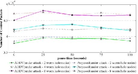
[image:7.595.59.279.614.728.2]Fig 6: Comparing overhead in AODV and the proposed technique in case of 2, 4, and 8 wormhole nodes.
In conclusion the proposed technique gives the smallest packet loss rate compared with other techniques without significant increase in the overhead compared with the original AODV protocol.
5.
CONCLUSION
In this paper, a lightweight and reliable technique is proposed to detect and prevent wormhole attacks in AODV. The proposed technique uses a trusted backbone network of mobile nodes to periodically estimate a monitoring trust value for each node and evaluate the behavior of each other as well as the behavior of the regular nodes. The backbone network is constructed from the regular nodes chosen based on their trust value. AODV HELLO messages are used to exchange all the control information of the proposed technique to reduce the overhead. The simulation results using NS2 show that, the proposed technique can highly detect and remove the wormhole attack and gives the lowest total packet loss rate compared with AODV under attack and the other techniques.
6.
REFERENCES
[1] S. Basagni, M. Conti, S. Giordano, and I. Stojmenovic, “Mobile ad hoc networking”, Wiley, 2004.
[2] C.E. Perkins, E. Beliding-Royer, S. Das, “Ad hoc on-demand distance vector (AODV) routing”, IETF Internet Draft, MANET working group, Jan. 2004.
[3] N. Badache, D. Djenouri, and A. Derhab, “Mobility impact on mobile ad hoc routing protocols”, ACS/IEEE International Conference on AICCSA, Vol. 3, 2003.
[4] M. Su, “WARP: A wormhole-avoidance routing protocol by anomaly detection in mobile ad hoc networks”, Journal of Computer & Security, Elsevier, Vol. 29, No. 2, pp. 208-224, 2010.
[5] J. Von Mulert, I. Welch, and W. K.Seah, “Security threats and solutions in MANETs: A case study using AODV and SAODV”, Journal of Network and Computer Applications, Elsevier, Vol. 35, No. 4, pp. 1249-1259, 2012.
[6] The Network Simulator ns-2,
http://www.isi.edu/nsnam/ns/.
[7] B. Kannhavong, H. Nakayama, Y. Nemoto, N. Kato, and A. Jamalipour, “A survey of routing attacks in mobile ad hoc networks”, Journal of Wireless communications, IEEE,Vol. 14, No. 5, pp. 85-91, 2007.
[8] D. Cerri, and A. Ghioni, “Securing AODV: the A-SAODV secure routing prototype”, Communications Magazine, IEEE, Vol. 46, No. 2, pp. 120-125, 2008.
[9] I. Khalil, S. Bagchi, and N. B.Shroff, “LITEWORP: a Lightweight countermeasure for the wormhole attack in multihop wireless networks”, Proceedings of the international conference on dependable systems and networks (DSN’05), IEEE, pp. 612-621, 2005.
[10] Y. C. Hu, A. Perrig, and D. B. Johnson, “Wormhole Attacks in Wireless Networks”, IEEE Journal on Selected Areas in Communications, IEEE, Vol. 24, No. 2, 2006.
[11] Y. C. Hu, A. Perrig, and D. B. Johnson, “Packet leashes: a defense against wormhole attacks in wireless networks”, In INFOCOM 2003, Twenty-Second Annual Joint Conference of the IEEE Computer and Communications, IEEE Societies, Vol. 3, pp. 1976-1986, 2003.
[12] J. Eriksson, S. V. Krishnamurthy, and M. Faloutsos, “Truelink: A practical countermeasure to the wormhole attack in wireless networks”, Proceedings of the 2006 14th IEEE International Conference on in Network Protocols (ICNP'06), IEEE, pp. 75-84, 2006.
[13] X. Wang, and J. Wong, “An end-to-end detection of wormhole attack in wireless ad-hoc networks”, In Computer Software and Applications Conference (COMPSAC), IEEE, Vol. 1, pp. 39-48, 2007.
[14] Hu, L., and D. Evans, “Using Directional Antennas to Prevent Wormhole Attacks”, Proceedings of Network and Distributed System Security Symposium (NDSS), 2004.
[15] I. Khalil, S. Bagchi, and N. B. Shroff, “MOBIWORP: Mitigation of the wormhole attack in mobile multihop wireless networks”, Journal of Ad Hoc Networks, Elsevier, Vol. 6, No. 3, pp. 344-362, 2008.
[16] M. A. Azer, S. M. El-Kassas, A. W. F. Hassan, and M. S. El-Soudani, “Intrusion Detection for Wormhole Attacks in Ad hoc Networks: A Survey and a Proposed Decentralized Scheme”, IEEE Conference on Availability, Reliability and Security (ARES 08), pp. 636-641, 2008.
[17] M. R. Alam, and K. S. Chan, “RTT-TC: A topological comparison based method to detect wormhole attacks in MANET”, IEEE Conference on Communication Technology (ICCT), pp. 991-994, 2010.
[18] F. Shi, D. Jin, W. Liu, and J. Song, “Time-based detection and location of wormhole attacks in wireless ad hoc networks”, IEEE conference on Trust, Security and Privacy in Computing and Communications (TrustCom), pp. 1721-1726, 2011.
[19] M. Poturalski, P. Papadimitratos, and J. P. Hubaux, “Secure neighbor discovery in wireless networks: formal investigation of possibility”, ACM symposium on Information, computer and communications security, pp. 189-200, 2008.
[20] S. Hariharan, N. B. Shroff, and S. Bagchi, “Secure neighbor discovery through overhearing in static multihop wireless networks”, Journal of Computer Networks, Elsevier, Vol. 55, No. 6, pp. 1229-1241, 2011.
[22]S. M. Glass, V. Muthukkumarasamy, and M. Portmann, “Detecting man-in-the-middle and wormhole attacks in wireless mesh networks”, IEEE conference on Advanced Information Networking and Applications (AINA'09), pp. 530-538, 2009.
[23]L. F. Garcia, and J. M. Robert, “Preventing layer-3 wormhole attacks in ad-hoc networks with multipath DSR”, IEEE Ad Hoc Networking Workshop (Med-Hoc-Net 2009), pp. 15-20, 2009.
[24]Sahu, K. R., and D. N. S. Chaudhari, “Efficient Techniques to Detect the Various Attacks in Ad-Hoc Network”, International Journal of Electronics and Computer Science Engineering (IJECSE, ISSN: 2277-1956), Vol. 1, No. 04, pp. 2362-2367, 2012.
[25]Zhen, J., and S. Srinivas, “Preventing replay attacks for secure routing in ad hoc networks”, Proceedings of
Ad-Hoc, Mobile, and Wireless Networks, Springer, pp. 140-150, 2003.
[26] R. S. Khainwar, A. Jain, and J. P. Tyagi, “Elimination of Wormhole Attacker node in MANET using performance evaluation multipath algorithm”, Journal of Network and Complex Systems, IISTE, Vol. 3, No. 7, pp. 22-29, 2013.
[27] I. Khalil, S. Bagchi, and N. B.Shroff, “LITEWORP: a Lightweight countermeasure for the wormhole attack in multihop wireless networks”, Proceedings of the international conference on dependable systems and networks (DSN’05), IEEE, pp. 612-621, 2005.