Technology (IJRASET)
Comparative Analysis of Energy-Efficient Protocol
LEACH, PEGASIS and GA-PEGASIS in Wireless
Sensor Networks
Kawal Nain
1,
Manpreet Kaur (Asstt. Professor) 2Yadavindra College of Engineering
Abstract- Wireless Sensor Network is a collection of small sensor nodes with ability to sense, compute and transmit data that are deployed to observe a physical environment. Data dissemination and gathering protocols design for Wireless Sensor Network is crucial challenge since these protocols are should be easy, energy efficient and robust to deal with such a large number of nodes. LEACH is a hierarchical protocol in which most of the nodes transmit data to cluster heads, and the cluster heads aggregates and compresses the data and forward it to the Base station (sink). PEGASIS (Power-Efficient Gathering in Sensor Information Systems), a near optimal chain based protocol that is an improvement over LEACH. In PEGASIS, each node communicates only with a close neighbor and takes turns transmitting to the base station, In chain based routing protocol a node called leader node forwards the data to the Base station. Genetic algorithm is for generate balanced and energy efficient data aggregation spanning trees for wireless sensor networks. Genetic algorithm contains chromosome with appropriate fitness value. Genetic algorithm consists of selection operator, crossover operator and mutation operator. These operators’ gives help to get better lifetime over LEACH and PEGASIS. By simulation, it is proved that the proposed algorithm allows network stability extension as compared to the most known chaining algorithm
Keywords: - Wireless Sensor Networks, LEACH, PEGASIS, GA-PEGASIS, Average Round time.
I. INTRODUCTION
Wireless sensor networks are distributed networks of small light weight nodes that are arranged in large area. A wireless sensor network is capable of performing some processing, gathering sensory information and communicating with other connected nodes in the network. It first senses the data and then it process that data. After processing, it route that data to base station through communication medium. WSN nodes are typically organized in one of three types of network topologies that are star topology, cluster tree network and mesh topology. In a star topology, each node connects directly to a gateway. In a cluster tree network, each node connects to a node higher in the tree and then to the gateway and data is routed from the lowest node on the tree to the gateway. This mesh link is often referred to as a route. Wireless sensor network with the characteristic of low energy, low cost and self organization have brought the revolution in the information perception. The energy of the nodes is limited, due to that deployment in complicated environments, the sensor nodes are difficult to get their energy or replace once their energy will lost. Meanwhile the sensor networks have minimum communication lifetime. To optimize the communication path and improve the lifetime has become an important issue of designing routing protocol for wireless sensor networks. To overcome such design issues there are various routing protocol in the network.
II. LOWENERGYADAPTIVECLUSTERINGHIERARCHY (LEACH)
Technology (IJRASET)
T (n) =∑ P⁄ (1-P (rmod(1⁄P)))
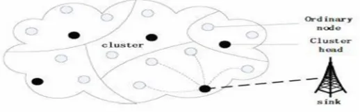
[image:3.612.154.413.189.270.2]Where P is the desired percentage of cluster heads, r is the current round, and G is the set of nodes that have not been cluster head in the last 1/P rounds. After the cluster heads are selected, the cluster heads. All the nodes in a network organize themselves into local clusters, with their cluster head. In a particular cluster every nodes selected for the cluster head on the basis of the probability. Every node has the probability of being the cluster head is 1/P. All the non-cluster head nodes transmit their data to the cluster-head, while the cluster-head node receive data from the cluster members, perform signal processing functions on the data (e.g., data aggregation), and transmit data, then every cluster head of the network transmit the data to the base station.
Fig 1.LEACH OPERATION
Therefore, being a cluster-head node is much more energy-intensive than being a non-cluster-head. Thus, when the cluster head loses it energy it dies, that result the communication process will disturb. To avoid such incontinences it incorporates randomized rotation of the high-energy cluster-head position such that it rotates among the sensors. In order to avoid draining the battery of any one sensor in the network. In this way, the energy load associated with a cluster-head is evenly distributed among the nodes. Leach achieves over a factor of 7 times and 8 times reduction in energy dissipation as compared to the direct link communication.
A. Network Model
In this paper, for the simplification of the network model there are assumptions that the WSN have the following properties.
1) N Sensor nodes are distributed randomly in the square field.
2) All the nodes in the network are homogenous and energy constrained.
3) The Base Station is fixed and located far from the Sensor is not energy constrained.
4) The nodes always have the data to send to the Base Station and nodes located close to the each other have correlated data.
5) All nodes can adjust their transmit power.
B. Energy Consumption Model
According to the radio energy dissipation model, the energy consumption of transmitting l-bit data over a distance d is
ETX(l,d) = { lEelec + lEfsd2 if d<do}
{ lEelec + lEmpd2 if d>d0}
Here d is the distance, Eelec represents the energy consumption in the electronics for sending or receiving one bit, And Efs and Emp
are the amplifier energy depends on amplifier transmission energy.
III. PEGASIS (Power Efficient Gathering in Sensor Information System)
Technology (IJRASET)
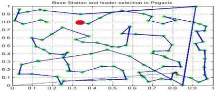
[image:4.612.198.415.167.260.2]This result PEGASIS can save energy as compared to LEACH. In the chain construction phase first initialize the network parameter like initial energy, number of nodes, transmit energy, and receive energy and the location of the Base station. Then the chain construction phase start. Then the base station broadcast the acknowledgment message to every alive node to obtain the information about the node ID. In this process node which is at far distance is considered as BS, because BS is not energy constrained node. From the BS chain formation will start after calculating the distance between the nodes and formation of chain start. In this process there is one more node known as leader node. Leader node aggregates the data from the chain and sends the data to the sink.
Fig 2. PEGASIS OPERATION
C. Steps in PEGASIS protocol
1) Initializing the WSN parameters.
2) Deploy the N number of nodes.
3) Initialize the PEGASIS parameter for routing.
4) Implementing the PEGASIS protocol.
5) Routing update with each round.
6) Checking the lifetime and data consumption.
D. Radio model for PEGASIS
In this model, a radio dissipates the energy while transmitting the data as well as receiving neglecting the all the loses due to environment condition. In this model, a radio dissipates Eelec=50nJ/bit to run the transmit and Eamp= 100pJ/bit for the transmitter
amplifier. The radios have power control and can expend the minimum required energy to reach the destination. The radios can be turned off to avoid receiving unintended transmission. The equation used to calculate transmission costs and receiving costs or a k-bit message and a distance d are shown below.
Tranmitting Energy
ETX(k,d)= ETX – elec(k) + ETX –amp(k,d)
Receiving Energy
ERX(k)= ERX – elec(k)
IV. GENETIC ALGORITHM
Technology (IJRASET)
mutation operation, new genetic properties are inserted in the offspring.
E. Genes and Chromosomes
In this, data routing chain is represented by means of chromosomes, which consist of the genetic information for the genetic algorithm. A chromosome is a collection of genes and each chromosome represents an which is determined by the number of nodes in the network. A gene index represents a node's identification number (ID) and the gene value indicates the node's parent ID.
F. Selection Operator
It is the process which equates the survival of the better genes to the next generation. The fitness of each individual depends on the fitness function.
This equation is considered in terms of chain related to distance only, which is responsible for energy consumption. This equation has chromosome C containing N genes and di denotes the distance between the (i+1) node and the ith node in the data gathering
chain. Greater value of the chromosome energy indicates the longer chain.
G. Crossover
It indicates the combination of the two parent chromosomes to produces an offspring in the next generation.
For this we have P1 = {2,6,5,8,9,4} and P2 = {1,5,7,9,2,3} are the two parent chromosomes selected for crossover. The slot {8, 9, 4}
is randomly selected from the first parent and inserted into the second parent at the same position in the second parent and resulting get the offspring O = {1,5,7,8,9,4}.
H. Mutation
It involves the variation in the new generation. It obtains a randomly picked slot from the best chromosome and inserted into the offspring. Some time it generates an invalid chromosome which violates the constraints imposed in the optimization problem such as distance threshold, then the solution will be rejected and the crossover operation will perform again.
V. SIMULATION AND RESULTS
It involves the simulation of all the three protocol; it includes the network lifetime based on the alive nodes, dead nodes at different energy of 0.25nJ and 0.5nJ. It also includes the energy dissipation at 0.5nJ From the simulation it is concluded that the GA-PEGASIS is better lifetime than all the protocols.
gene index 0 1 2 3 4 5 6 7 . . . 99
gene value 70 30 70 10 12 18 25 10 . . . 80
Technology (IJRASET)
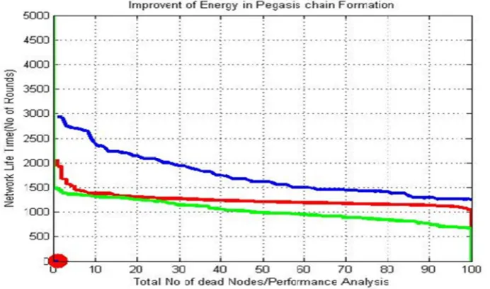
Fig 3: Comparison of LEACH, PEGASIS and GA-PEGASIS at initial energy of 0.5
A. Comparison Results
It involves the simulation of all the three protocol, it includes the network lifetime based on the alive nodes, dead nodes at different energy of 0.25nJ and 0.5nJ. It also includes the energy dissipation at 0.25 From the simulation it is concluded that the GA-PEGASIS is better lifetime than all the protocols.
Fig 4. Comparison of LEACH, PEGASIS and GA-PEGASIS at 0.25nJ
B. Comparison Result
[image:6.612.79.425.412.616.2]Technology (IJRASET)
Table 1: Comparison table of LEACH, PEGASIS and GA-PEGASIS at initial energy 0.25J
Nodes
Number of Rounds
Leach Pegasis GA-Pegasis
100 750 1100 1300
90 800 1120 1400
80 850 1400 1500
70 900 1170 1600
60 950 1200 1700
50 1000 1230 1850
40 1020 1250 1950
30 1150 1300 2250
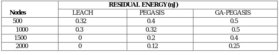
C. Comparison Result of Residual Energy
[image:7.612.76.536.321.413.2]It includes the comparison result on the basis of the residual energy. This concludes the energy of all the protocol which is carried out in this thesis work. This gives the residual value of all the protocol as following.
TABLE 2: Comparison result of Residual energy at 0.5nJ.
Nodes
RESIDUAL ENERGY(nJ)
LEACH PEGASIS GA-PEGASIS
500 0.32 0.4 0.5
1000 0.3 0.32 0.5
1500 0 0.2 0.4
2000 0 0.12 0.25
REFERENCES
[1] A. Seetharam, A. Acharya , A. Bhattacharyya , M. K. Naskar , “An Energy Efficient Data Gathering Protocol for Wireless Sensor Networks ” ,Journal of Applied Computer Science, vol no.5 (3) ,pp. 19-27, May 2009.
[2] Cosmin Cirstea, “Energy Efficient Routing Protocol for Wireless Sensor Network: A Survey”, vol no. 2(3), pp.277-282, oct 2011.
[3] Dervis Karaboga, Selcuk Okdem, “Routing in Wireless Sensor Networks Using an Ant Colony Optimization (ACO) Router Chip”article, pp.909-921, Febrary 2009.
[4] Feng Sen, “ An Improved Energy Efficient Pegasis Based Protocol in Wireless Sensor Network,” International Journal on Fuzzy System Knowledge, vol. 1, pp.2230-2233, January 2011
[5] Gurbhej Singh,Harneet Arora, “Design and Architectural Issues in Wireless Sensor Networks”,International Journal of Advanced Research in Computer Science and Software Engineering, vol no.3(7), pp.1375-1381, January – 2013
[6] J.Zhong Y-F Fung, “Case study and proofs of ACO improved particle filter algorithm”, journal of Control Theory and application, vol no. 6(5), pp 687-697, June 2011