Implementation of FPGA for Decision Making for
IC’S Library
Sanjay Chowdhary1, Shashidhar P.K2, Manjunathraddi Bentur3, Sunil Begumpur4
1, 2, 3, 4
Dept. of Electronic and Communication, SKSVMACET Laxmeshwar, Gadag
Abstract; The functional testing of integrated circuits using FPGA. Using this technique will lead to get the decision making if the module functions properly or not. This implementation consists of both tester Hardware and its corresponding Software. This Design and Implementation is compact, small and requires low power hence this is an inexpensive design. Here FPGA based digital IC tester is designed using Very High Speed Integrated Circuit Hardware description language (VHDL).
I. INTRODUCTION
Integrated Circuits (ICs) mean that all the components in the circuit are fabricated on the same “chip”. Integrated Circuits have become a vital part of modern electronic circuit design. They are used in the computer industry, automobile industry home appliances, communication and control Systems, where they permit miniaturization and superior performances not possible with discrete components. Integrated Circuits are now being used in all types of electronic equipment because of the long, trouble-free service they provide. In addition, they are economical because they are mass produced. Digital Integrated Circuits are complete functioning logic networks that are equivalence of basic transistor logic circuits. They are used two form such circuits as gates, counters, multiplexers, de-multiplexers, shift registers, and others since a digital IC is a complete predesigned package, it usually requires nothing more than a power supply, input and output. In Today’s Electronics world, 90% of electronic components sold in market is digital, so the need for Digital test equipment is very relevant. The Integrated Circuit tester available in the market tests only limited series of IC’s, which is not desirable or affordable. It is necessary to test functionalities of all Sequential, Combinational circuits, Processors, SOC, PCB and Motherboard using unique device in lesser time and Automated Test Equipment (ATE) serves the above requirements. This project proposes the design and implementation of a compact, small, cheap Integrated Circuit tester. The system is described as the implementation of a PC-based logic system which used Very High Speed Integrated Circuits Hardware Description Language (VHDL) code program. The system is suitable for either small-scale chip or printed circuit board testing in a quick and efficient usage. Using this technique will lead to get the decision making if the module is function properly or not. This environment consists of the tester hardware and its corresponding software which enables both engineers and technicians to experience the challenges of testing and debugging without the expense of costly commercial hardware testers. A simple circuit is constructed using breadboards, wires, along with Device under Tests (DUT's), then testing using switches and Light Emitting Diodes (LED's). By implementation of this technique a digital Integrated Circuit tester sends a sequence of test vectors to a DUT, receives the actual response vectors from the DUT, and compares the responses from the DUT to the expected stored response vectors to determine and decide whether DUT is functioning properly or not. So finally we are able to get decision making. The problem is how to apply the required test patterns to the Device under Test (DUT) and to analyze the response to locate the faulty components so that the integrated circuit returned to service. The Automatic Test Equipment (ATE) achieves this objective. It produces input test patterns and check binary outputs for correctness. The required test fixture is the edge connector that it is inexpensive and simple to construct. The system consists of DUT (4 gates, 2 gates, 3 gates), PC-based logic system which used to download a VHDL written program into a Field Programmable Gate Array (FPGA), and a parallel cable for interfacing which makes the system suitable for either small-scale chip or printed circuit board testing in a quick and efficient usage. The VHDL resulting program can be easily modified and re-downloaded as needed. In this project, the FPGA implementation is used. The concept of the portable ATE is presented to reduce the complexity of the traditional ATE. Testing of Digital integrated Circuits using automatic test equipment is very costly. Instead using reconfigurable FPGA, can save money as well as by small change in coding (Verilog or VHDL etc.), it can be reconfigured for different Integrated Circuits testing.
A. Problem Statement
The VLSI circuit manufacturers cannot guarantee defect-free integrated circuits (IC’s). Circuit complexity, IC defect anomalies, and economic considerations prevent complete validation of VLSI circuits. Testing digital circuits for correct operation after
B. Objectives
1) To save time by testing IC’s in a parallel manner.
2) To check the particular gates of IC’s.
3) To provide low cost IC tester.
II. PROPOSED SYSTEM
Testing digital IC’s for a correct operation after manufacturing is an important problem. The problem is how to apply the required test patterns to the Device under test (DUT) and to analyze the response to locate the faulty components so that the circuit board returns to service. The Automatic Test Equipment (ATE) achieves this objective. It produces input test patterns and check binary outputs for correctness. In this paper we propose a reconfigurable system called FATE (FPGA-based ATE). FATE allows executing home-made digital tests, only using a Laptop and a FPGA based board and can be easily modified accordingly to the DUT (Device Under Test)saving time and money. Test pattern generation plays the major role in ATE machine.
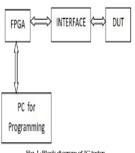
[image:3.612.213.444.259.521.2]A. Working Procedure
Fig. I :Block diagram of IC tester
The block diagram of IC_TESTER is shown in fig I. The system is described as the implementation of a PC-based logic system which used Very High Speed Integrated Circuits Hardware Description Language (VHDL) code program. The system is suitable for small-scale chip. The system consists of personal computer (PC), DUT (4 gates, 2 gates, 3 gates) and parallel cable (JTAG) for interfacing. It provides 63 bidirectional input/output (I/O) ports of the FPGA to the DUT which has library of 57 Dual in Package (DIP) chips (14 pin types). It consists of Joint Test Action Group (JTAG) programmer. Initially, we create a virtual ROM by using a VHDL code. In a virtual ROM we store an expected output of device under test (DUT). The DUT is setup by simply connecting power and ground wires and plugging it into the circuit.
The construction of the IC TESTER is such that there is DUT and Virtual ROM, which has the correct output of the ICs in the library, and the FPGA which has a program as a VHDL code, which executes the function of all ICs in the library.
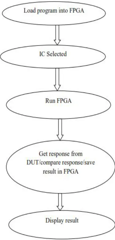
B. Flow diagram
Fig II: Flow Diagram of IC testing
III. RESULTS
Fig III: 2 inputs gate simulation result Fig VI:3 inputs gate simulation result
Fig V: 4 inputs gate simulation result Fig VI: simulation result of all 3 IC’s
IV. FUTURE IMPLEMENTS
A. If any complexities arise in the program storing then the virtual rom is replaced by EEPROM.
B. The required input is applied to the ICs for checking and condition of the IC and display output in the LCD by displaying
“GOOD” or “BAD” along with the IC number.
C. Xilinx software can be monitored by android app to test ICs.
V. CONCLUSION
This kind of testing is very cheap, reconfigurable, user friendly. Different digital IC’s can be tested by just writing the specific program without any change in hardware. The implementation of the tester using xilinx FPGA increases the circuit density and reduces the cost, also it can be used to add features and fix design bugs after fabrication of printed-circuit board, and moreover FPGA reprogram ability yields to a much more engineer friendly tester. FPGA consume little power in order of only a few mill amperes per pin; the chip xilinx pin driver is protected such that it often prevents the user from destroying a tested chip that was installed or programmed improperly.
REFERENCES
[1] “Implementation of Field Programmable Gate Array (FPGA) for decision making in Portable automatic testing systems for IC’s library & digital circuits” M. S. Zaghloul M. Saleh, 2011, IEEE.
[2] ”FPGA based digital IC tester” 1Sandhay Singh Tripaliya, 2P.P.BANSOD 1Student’ E&I Department, SGSITS Indore 2HOD, Biomedical Engineering Department, SGSITS Indore Email: [email protected], [email protected]
[3] Implementation of an integrated FPGA based automatic test equipment and test Generation for digital circuits.” K. Vanitha. ME-VLSI DESIGN, Arunai
College of Engg, Tiruvannamalai. C. A. Sathiya Moorthy, Asst Prof & HOD (ECE), Arunai College of Engg,