Thrust Enhancement of a Convergent-Divergent
Nozzle by Using CFD
Srinivas M1, Suresh A L2, G. Harish3
1, 2
PG Student, 3Professor, Department of Mechanical Engineering, UVCE, Bangalore, (KA) India
Abstract: The CFD analysis of a convergent-divergent nozzle has been conducted at various divergent angles. Different geometries of nozzles have been created by changing the divergent angle. For modeling and meshing of nozzle, ICEM CFD was used and for analysis CFX-12.0 was used. The inlet boundary conditions were specified according to the available information. Here k-epsilon turbulence model is used. Governing equations were solved using the finite volume method in ANSYS CFX software. Results are obtained by CFD-POST. Exit velocity and Mach number was increased with increase in divergent angle. Based on the maximum exit velocity obtained, that nozzle geometry is optimized. For still more increase in the exit velocity, radius at the throat has been done on the optimized model and analysis was been carried out. Exit velocity was increased to certain extent and this was taken as final optimized model. Therefore, the final optimized nozzle will reduce the fuel consumption and shock’s formation, increases the thrust and exit velocity to a maximum level.
Keywords: Exit velocity, Thrust, Divergent angle, Computational fluid dynamics, ICEM CFD and CFX-12.0
I. INTRODUCTION
A nozzle is a device that increases the velocity of a fluid at the expense of pressure. Nozzle is a part of rocket which is used for the expansion of combustion gases through it and produces thrust. Nozzle is a passage used to transform pressure energy into kinetic energy. During the combustion of fuel, chemical energy is converted into thermal energy and pressure energy. The combustion gases at this stage are at a high pressure and temperature and these gases under such high pressure expand through the nozzle during which the pressure energy is converted into kinetic energy which in turn moves the vehicle in a direction opposite to that of the exhaust gases, according to Newton’s third law of motion. Two primary functions of nozzle are - First, they must control the engine back pressure to provide the correct and optimum engine performance, which is done by jet area variations. Second, they must efficiently convert potential energy of the exhaust gas to kinetic energy by increasing the exit velocity, which is done by efficiently expanding the exhaust gases to the atmospheric pressure.
II. LITERATURE SURVEY
Arjun Kundu, Devyanshu Prasad and Sarfraj Ahmed [1] worked on the topic of “Effect of Exit Diameter on the Performance of Converging-Diverging Annular Nozzle Using CFD” and there findings are - The result obtained after the CFD analysis shows that smaller exit diameter gives greater mach number compared to the larger diameter for the same inlet and boundary conditions. K.M. Pandey, Surendra Yadav and A.P. Singh [2] worked on the topic of “Study on Rocket Nozzles with Combustion Chamber Using Fluent Software at Mach 2.1” and his findings are - The pressure and Temperature parameter depends upon air-fuel ratio. Mohan Kumar G, Dominic Xavier Fernando and R. Muthu Kumar [3] worked on the topic of “Design and Optimization of De Laval Nozzle to Prevent Shock Induced Flow Separation” and there findings are - For maximum thrust and efficiency without flow separation due to induced shock, the direction of flow of stream through nozzle should be axial. Venkatesh V, C Jaya pal Reddy [4] worked on the topic of “Modelling and Simulation of Supersonic nozzle using Computational Fluid Dynamics” and there findings are - Contour nozzle gives a greater mach number at exit compared to conical nozzle because contour nozzle gives maximum expansion ratio.
III. CFD ANALYSIS OF A NOZZLE A. Modeling
ICEM CFD is used to create a 3D geometry of a nozzle for CFD analysis as shown in above fig. 1, According to the available dimensions; the convergent-divergent nozzle was created. The nozzle dimensions are as follows:
Inlet diameter (di) = 1m Throat diameter (d*)= 0.509m Exit diameter (de) = 1.273m Convergent length = 0.64m
Convergent Angle (α) = 21o
B. Meshing
ICEM CFD is used for meshing the model for CFD analysis. The type of mesh used is unstructured mesh. In unstructured mesh the shape of each element is tetrahedral.
Fig-2: Meshed Model
C. Pre-Processing
Appropriate boundary conditions are specified by using ANSYS CFX-12.0 software in the pre-processing stage. CFX software is a very powerful tool with many advanced features. The complete boundary condition details are as follows:
Turbulence model: k-epsilon 1) Location inlet
Pressure: 44.1bar Temperature: 3400k
Fig-3: Boundary Conditions
Mass-flow rate = 826 kg/sec 2) Location wall
Mass and Momentum: No slip wall Wall Roughness: Smooth wall 3) Location outlet
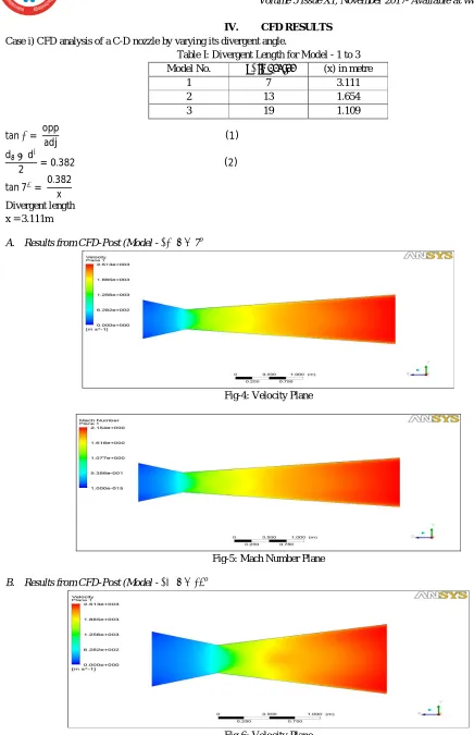
IV. CFD RESULTS Case i) CFD analysis of a C-D nozzle by varying its divergent angle.
Table I: Divergent Length for Model - 1 to 3 Model No. (β) in degree (x) in metre
1 7 3.111
2 13 1.654
3 19 1.109
tanβ= opp
adj (1)
d −d∗
2 = 0.382 (2)
tan 7 = 0.382
x
Divergent length x = 3.111m
A. Results from CFD-Post (Model - 01) β = 7o
Fig-4: Velocity Plane
Fig-5: Mach Number Plane
[image:4.612.59.495.53.728.2]B. Results from CFD-Post (Model - 02) β = 13o
Fig-7: Mach Number Plane
C. Results from CFD-Post (Model - 03) β = 19o
Fig-8: Velocity Plane
Fig-9: Velocity Vector
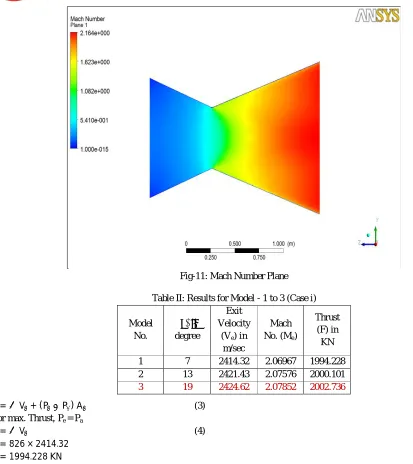
Fig-11: Mach Number Plane
Table II: Results for Model - 1 to 3 (Case i)
Model No. (β) in degree Exit Velocity (Ve) in m/sec Mach No. (Me) Thrust (F) in KN
1 7 2414.32 2.06967 1994.228
2 13 2421.43 2.07576 2000.101
3 19 2424.62 2.07852 2002.736
F =ṁ V + (P −P ) A (3)
For max. Thrust, Pe = Pa
F =ṁ V (4)
F = 826 × 2414.32 F = 1994.228 KN
From CFD analysis of Case i, the exit velocity is more for Model - 3 as compared to other nozzle models. Therefore, Model - 3,
β = 19o has been optimized.
Case ii) CFD analysis of a C-D nozzle for radius at the throat.
Table III: Throat Radius for Model - 3.1 to 3.3
Model No. Throat Radius (r) in m
3.1 0.12725
3.2 0.2545
3.3 0.38175
Throat radius
r = 0.25 to 0.75 × d∗ (5) r = 0.25 × 0.509
D. Results from CFD-Post (Model - 3.1)
Fig-12: Velocity Plane
Fig-13: Mach Number Plane
E. Results from CFD-Post (Model - 3.2)
Fig-14: Velocity Plane
F. Results from CFD-Post (Model - 3.3)
Fig-16: Velocity Plane
Fig-17: Velocity Vector
Fig-18: Velocity Streamline
Table IV: Results for Model - 3.1 to 3.3 (Case ii)
Model No.
Throat Radius (r) in m
Exit Velocity (Ve) in m/sec Mach No. (Me) Thrust (F) in KN
3.1 0.12725 2433.82 2.0864 2010.335 3.2 0.2545 2436.89 2.08915 2012.871 3.3 0.38175 2437.86 2.09011 2013.672
From CFD analysis of Case ii, the exit velocity is more for Model - 3.3 as compared to other nozzle models. Therefore, Model -
3.3, β = 19o
, r3 = 0.38175m has been finally optimized.
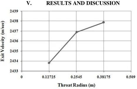
V. RESULTS AND DISCUSSION
[image:9.612.190.423.222.374.2]Fig-20: Throat Radius Vs Exit Velocity for Model - 3
Throat radius versus exit velocity and mach number for model - 3 is shown in fig. 20 and 21 respectively. The exit velocity, mach number and thrust values of model - 3.1 to 3.3 are mentioned in the table 4. In case i, the exit velocity was increased as the divergent angle was increased. For 19 degree divergent angle, the nozzle velocity was increased to certain extent so, model - 3 was optimized. From the CFD analysis for case ii, the model - 3.3 gives higher exit velocity and mach number as compared to all other nozzle models. Therefore, Model - 3.3, β = 19o, r3 = 0.38175m has been finally optimized. All the conditions for supersonic flow of nozzle has been achieved in this CFD analysis.
Fig-21: Throat Radius Vs Mach number for Model - 3
VI. CONCLUSION
A. Nomenclature
d diameter, m
P Pressure, bar
T Temperature, K
ṁ mass-flow rate, kg/sec
F Thrust, KN
V Velocity, m/sec
d* Throat diameter, m
M Mach number
x Divergent length, m
Greek symbols
ρ Density, kg/m3
α Convergent angle, degree
β Divergent angle, degree
Subscript
i inlet
e exit
a ambient
REFERENCES
[1] Arjun Kundu, Devyanshu Prasad, Sarfraj Ahmed, “Effect of Exit Diameter on the Performance of Converging-Diverging Annular Nozzle using CFD”,
International Journal of Innovative Research in Science, Engineering and Technology, Vol. 5, Issue 6, June 2016.
[2] K.M. Pandey, Surendra Yadav and A.P. Singh, “Study on Rocket Nozzles with Combustion Chamber Using Fluent Software at Mach 2.1”, The 10th
Asian Symposium on Visualization, SRM University, Chennai, March 1-5, 2010, pp. 171-177.
[3] Mohan Kumar G, Dominic Xavier Fernando, R. Muthu Kumar, “Design and Optimization of De Laval Nozzle to Prevent Shock Induced Flow
Separation”, Advances in Aerospace Science and Applications, ISSN 2277-3223 Volume 3, Number 2, 2013, pp. 119-124.
[4] Venkatesh V, C Jaya pal Reddy, “Modelling and Simulation of Supersonic Nozzle using Computational Fluid Dynamics”, International Journal of Novel
Research in Interdisciplinary Studies, ISSN: 2394-9716, Vol. 2, Issue 6, Nov-Dec 2015, pp. 16-27.
[5] Biju Kuttan P, M Sajesh, “Optimization of Divergent Angle of a Rocket Engine Nozzle Using Computational Fluid Dynamics”, The International Journal
Of Engineering And Science (IJES), Volume 2, Issue 2, 2013, ISSN: 2319-1813 ISBN: 2319-1805, pp. 196-207.
[6] John D. Anderson, Jr., Computational Fluid Dynamics - The Basics with Applications, McGraw-Hill International Edition, 1995.
[7] H. K. Versteeg and W. Malalasekera, An Introduction to Computational Fluid Dynamics The Finite Volume Method, First Edition, 1995.
[8] S.M. Yahya, Fundamentals of Compressible Flow with Aircraft and Rocket Propulsion, New Age International Publishers, Third Edition.
[9] Dr. R. Yadav and Sanjay and Rajay, Steam & Gas Turbines and Power Plant Engineering, Central Publishing House, 7th Revised and Enlarged Edition,
2004.
[10] MD. Safayet Hossain, Muhammad Ferdous Raiyan and Nahed Hassan Jony, “Comparative Study of Supersonic Nozzles”, International Journal of
Research in Engineering and Technology (IJRET), Vol. 3, Issue 10, Oct 2014, eISSN: 2319-1163, pISSN: 2321-7308, pp. 351-357.
[11] Nikhil D. Deshpande, Suyash S. Vidwans, Pratik R. Mahale, Rutuja S. Joshi, K. R. Jagtap, “Theoretical and CFD Analysis of De Laval Nozzle”,
International Journal of Mechanical And Production Engineering, ISSN: 2320-2092, Volume 2, Issue 4, April 2014, pp 33-36.
[12] Abdul Hadi Butt and Asfandyar Arshad, “Design and Analysis of a Clustered Nozzle Configuration and Comparison of its Thrust”, Student Research
Paper Conference, Vol. 2, No. 19, July 2015, pp. 105-109.
[13] G. Satyanarayana, Ch. Varun, S.S. Naidu, “CFD Analysis of Convergent-Divergent nozzle”, Acta Technica Corviniensis - Bulletin of engineering, Tome
VI, ISSN 2067-3809, July-Sept 2013, pp. 139-144.
[14] Pardhasaradhi Natta, V. Ranjith Kumar, Dr. Y. V. Hanumantha Rao, “Flow Analysis of Rocket Nozzle using Computational Fluid Dynamics (CFD)”,
Engineering Research and Applications (IJERA) ISSN: 2248-9622 www.ijera.com Vol. 2, Issue 5, September - October 2012, pp.1226-1235.
[15] CH. Sriivasa Chakravarthy, R. Jyothu Naik, “Analysis of Flow in a De Laval Nozzle using Computational Fluid Dynamics”, Proceedings of International