www.hydrol-earth-syst-sci.net/18/5149/2014/ doi:10.5194/hess-18-5149-2014
© Author(s) 2014. CC Attribution 3.0 License.
Analyzing runoff processes through conceptual hydrological
modeling in the Upper Blue Nile Basin, Ethiopia
M. Dessie1,2, N. E. C. Verhoest2, V. R. N. Pauwels5, T. Admasu3,4, J. Poesen6, E. Adgo3, J. Deckers6, and J. Nyssen4 1School of Civil & Water Resources Engineering, Bahir Dar University, P.O. Box 430, Ethiopia
2Laboratory of Hydrology and Water Management, Ghent University, Coupure links 653, 9000 Gent, Belgium 3College of Agriculture & Environmental Sciences, Bahir Dar University, P.O. Box 79, Ethiopia
4Department of Geography, Ghent University, Krijgslaan 281 (S8), 9000 Gent, Belgium 5Department of Civil Engineering, Monash University, Clayton, Victoria, Australia 6Department of Earth and Environmental Sciences, KU Leuven, Belgium
Correspondence to: M. Dessie ([email protected])
Received: 19 April 2014 – Published in Hydrol. Earth Syst. Sci. Discuss.: 20 May 2014 Revised: 14 October 2014 – Accepted: 11 November 2014 – Published: 12 December 2014
Abstract. Understanding runoff processes in a basin is of paramount importance for the effective planning and man-agement of water resources, in particular in data-scarce re-gions such as the Upper Blue Nile. Hydrological models rep-resenting the underlying hydrological processes can predict river discharges from ungauged catchments and allow for an understanding of the rainfall–runoff processes in those catch-ments. In this paper, such a conceptual process-based hy-drological model is developed and applied to the upper Gu-mara and Gilgel Abay catchments (both located within the Upper Blue Nile Basin, the Lake Tana sub-basin) to study the runoff mechanisms and rainfall–runoff processes in the basin. Topography is considered as a proxy for the variabil-ity of most of the catchment characteristics. We divided the catchments into different runoff production areas using to-pographic criteria. Impermeable surfaces (rock outcrops and hard soil pans, common in the Upper Blue Nile Basin) were considered separately in the conceptual model. Based on model results, it can be inferred that about 65 % of the runoff appears in the form of interflow in the Gumara study catch-ment, and baseflow constitutes the larger proportion of runoff (44–48 %) in the Gilgel Abay catchment. Direct runoff rep-resents a smaller fraction of the runoff in both catchments (18–19 % for the Gumara, and 20 % for the Gilgel Abay) and most of this direct runoff is generated through infiltration ex-cess runoff mechanism from the impermeable rocks or hard soil pans. The study reveals that the hillslopes are recharge areas (sources of interflow and deep percolation) and direct
runoff as saturated excess flow prevails from the flat slope areas. Overall, the model study suggests that identifying the catchments into different runoff production areas based on topography and including the impermeable rocky areas sep-arately in the modeling process mimics the rainfall–runoff process in the Upper Blue Nile Basin well and yields a use-ful result for operational management of water resources in this data-scarce region.
1 Introduction
The Upper Blue Nile Basin, the largest tributary of the Nile River, covers a drainage area of 176 000 km2and contributes more than 50 % of the long-term river flow of the Main Nile (Conway, 2000). The basin (Fig. 1a) drains the central and southwestern highlands of Ethiopia. The Ethiopian govern-ment is pursuing plans and programs to use the water re-source potential of the basin for hydropower and irrigation in an effort to substantially reduce poverty and increase agri-cultural production. The Grand Ethiopian Renaissance Dam near the Ethiopian–Sudan border is currently under construc-tion and several other water resource development projects are underway in its sub-basins.
Sus-tainable planning and development of the resources depend largely on the understanding of the interplay between the hy-drological processes and the availability of adequate data on river discharges in the basin. However, the available hydro-logical data are limited (for example, presently about 42 % of the Lake Tana sub-basin, the source of the Blue Nile, is gauged by the Ministry of Water Resources of Ethiopia). Furthermore, research efforts performed so far in the Upper Blue Nile Basin with respect to the basin characteristics, hy-drology and climatic conditions are scanty and fragmented (Johnson and Curtis, 1994; Conway, 1997; Mishra and Hata, 2006; Antar et al., 2006). Hydrological models that allow for a description of the hydrology of the region play an impor-tant role in predicting river discharges from ungauged catch-ments and understanding the rainfall–runoff processes in the catchments in order to enhance hydrological and water re-sources analysis. As such, a number of models have been developed and applied to study the water balance, soil ero-sion, climate and environmental changes in the Blue Nile Basin (e.g., Johnson and Curtis, 1994; Conway, 1997; Mishra and Hata, 2006; Kebede et al., 2006; Kim and Kaluarachchi, 2008; Collick et al., 2009; Steenhuis et al., 2009; Tekleab et al., 2011; Tilahun et al., 2013).
The Soil and Water Assessment Tool (SWAT) and the Hy-drologiska Byråns Vattenbalansavdelning Integrated Hydro-logical Modelling System (HBV-IHMS) models have been applied in the basin (Setegn et al., 2008; Wale et al., 2009; Uhlenbrook et al., 2010). The SWAT model is based on the Soil Conservation Service (SCS) runoff curve number ap-proach, where the parameter values are obtained empirically from plot data in the United States with a temperate climate. Liu et al. (2008) studied the rainfall–runoff relationships for the three Soil Conservation Research Project (SCRP) water-sheds (Hurni, 1984) in the Ethiopian highlands and showed the limitations of using such models, developed in temper-ate climtemper-ates, in monsoonal Ethiopia. Adjusted runoff curve numbers for steep slopes with natural vegetation in northern Ethiopia were reported by Descheemaeker et al. (2008).
Using a simple runoff-rainfall relation to estimate inflows to the Lake Tana from ungauged catchments, Kebede et al. (2006) computed the water balance of Lake Tana. How-ever, hills and floodplains were not differentiated in their sim-plified runoff-rainfall relations. Mishra et al. (2004) and Con-way (1997) developed grid-based water balance models for the Blue Nile Basin, using a monthly time step, to study the spatial variability of flow parameters and the sensitivity of runoff to climate changes. In both models, the role of to-pography was not incorporated, and in the model of Con-way (1997), soil characteristics are assumed spatially invari-ant. Very few of the model studies discussed above classi-fied the catchments into different hydrological regimes based on the relevant landscape characteristics to study the runoff mechanisms and the hydrological processes in the basin. Landscape characteristics can lead into conceptual struc-tures and relationships or the conceptual hydrological
mod-els can benefit from them (Beven, 2001). Istanbulluoglu and Bras (2005) considered topography as a template for various landscape processes that include hydrologic, ecologic, and biologic phenomena. This is more appealing to the Ethiopian highlands, in particular to the Upper Blue Nile Basin, as farming and farm drainage methodologies, soil and water conservation works, soil properties, vegetation, drainage pat-terns and density, and even rainfall, are much linked to topog-raphy in the Ethiopian highlands. Therefore, it remains nec-essary to investigate the hydrological processes in the Blue Nile Basin taking topography as a proxy for the variability of most of the catchment characteristics. The objective of this paper is to study runoff mechanisms in the Upper Blue Nile Basin using topography as the dominant landscape com-ponent and classify a catchment (as steep, medium and flat slope areas) into different runoff production areas. The study tries to identify the dominant rainfall–runoff mechanism on the hillslopes (steep and medium slop areas) and the valley bottoms (flat areas). A considerable portion of the mountain-ous areas in the Upper Blue Nile Basin consists of imperme-able rocks and hard soil pans, leading to a different runoff process. This paper further investigates the contribution of such landscapes in the rainfall–runoff process by including a class for these impermeable rock and hard soil surfaces in the conceptual hydrological model. This approach has not yet been tested in the Upper Blue Nile Basin. However, similar methodologies to the conceptual hydrological model devel-opment are discussed by Savenije (2010). Furthermore, it is necessary to obtain better quality river discharge data in the basin. In this paper, we will face all these challenges. The conceptual hydrological model for the rainfall–runoff stud-ies of the basin is calibrated using good-quality discharge data obtained from recently established measurement sta-tions. These outcomes positively add to the existing knowl-edge and contribute to the development of water resources plans and decision making in the basin.
2 Description of study catchments
of their territory are intensively cultivated. The lower flood-plains in these catchments with their buffering capacity are not considered by this study, but were discussed by Dessie et al. (2014).
The Gilgel Abay catchment (Fig. 1b) covers an area of 1659 km2at the gauging station near Picolo, with elevations ranging between 1800 and 3524 m a.s.l. Soils are character-ized by clay, clay loam and silt loam textures, each texture sharing similar proportions of the catchment area (Bitew and Gebremichael, 2011). The majority of the catchment is a basalt plateau with gentle slopes, while the southern part has a rugged topography.
The Gumara catchment covers part of the eastern side of the Lake Tana Basin. At its upper and middle portion, it has mountainous, highly rugged and dissected topography with steep slopes. The lower part is a valley floor with flat to gentle slopes. Elevation in the catchment varies from 1780 to 3700 m a.s.l. At the upper gauging station (Fig. 1b), the catchment area is 1236 km2. Two independent studies found very homogeneous textures of the soils in this catchment. BCEOM (1998) described it as dominantly clay with sandy clay soil at some places in the catchment, while soil data col-lected by Miserez (2013) show that texture is clay and clay loam. In the hilly catchments, clay soils are essentially Niti-sols, which do not present cracking properties as opposed to lowland Vertisols (Miserez, 2013).
Based on rainfall data from the Dangila and Bahir Dar sta-tions, observed in the period 2000 to 2011, mean annual fall is ca. 1500 mm, with more than 80 % of the annual rain-fall concentrated from June to September. Geologically, the catchments consist of Tertiary and Quaternary igneous rocks, as well as Quaternary sediments. The rivers in the hilly areas are generally bedrock rivers, whereas in the floodplain the rivers meander and sometimes braid (Poppe et al., 2013).
3 Model development
The model developed is based on a simple water balance approach and the studies by Jothityangkoon et al. (2001), Krasnostein and Oldham (2004) and Fenicia et al. (2008). The setup of this model is shown in Fig. 2. In this model-ing approach, the catchment is first split into soil surface and impermeable surface (these are areas with little or no soil cover and bedrock outcropping in the catchment as well as soils with well-developed tillage pans). The runoff from the presumed impermeable areas is modeled as infiltration ex-cess (Hortonian flow) runoff and is represented as QSe2. The other component of the catchment, recognized as the soil sur-face, is further divided into three using topographic criteria (slope), considering topography as a proxy for the variabil-ity of most of the catchment characteristics. Here, two reser-voirs are introduced (the soil reservoir and the groundwater reservoir). The slow-reacting reservoir (or the groundwater reservoir) is set to be common to all of the three slope-based
divisions of the catchment as it is quite inconsistent to sepa-rate the groundwater system in the catchment. The catchment buckets (reservoirs) and the conceptual runoff processes are depicted in Fig. 2b and c.
Jothityangkoon et al. (2001) conceptualized the upper soil layer (further referred to as the soil reservoir) as a “leaky bucket”. By adding a groundwater reservoir (Krasnostein and Oldham, 2004), the conceptual model for modeling the runoff at the catchment outlet was developed.
In Fig. 2,Q1[mm day−1] is the sum of direct runoff and interflow in the soil reservoir;Q2[mm day−1] is the baseflow from the groundwater reservoir; QSe2 is the direct runoff from impermeable surface of the catchment; and the sum of Q1 , Q2 and QSe2 forms the total river discharge, Q [mm day−1], at the outlet of a catchment.
The water storage at any time t within the soil reser-voir,S(t )in mm, is determined by the precipitation (P, in mm day−1), evapotranspiration (E
a, in mm day−1), and other catchment-controlled outputs (Fig. 2c (i–iii)). When the stor-age depth exceeds the field storstor-age capacity (Sf, in mm), precipitation is assumed to be partly transformed into sub-surface runoff, to represent inter- or subsub-surface flow (Qss, in mm day−1), and partly into deep percolation or recharge (R, in mm day−1) to the groundwater (Fig. 2c (ii)). When the soil reservoir fills completely, and the inflows exceed the outflows, surface runoff(Qse1, in mm day−1) is generated.
Quantitatively, the depth of water stored in the soil,S(t ), evolves over time using the water balance
S(t )=S(t−1t )+(P−Ea−Qss−Qse1−R)1t, (1) where P is the precipitation [mm day−1], E
a is the ac-tual evapotranspiration [mm day−1],S(t−1t )is the previ-ous time step storage [mm],Qssis the interflow or subsur-face runoff [mm day−1],Qse1 is the direct or overland flow from the soil reservoir [mm day−1],Ris deep percolation or recharge to the substrata and groundwater [mm day−1] and
1tis the time step equal to 1 day.
Different studies show that part of the interflow water from the steep hills appears at the hill bottoms during wet periods in the form of increased moisture content or overland flow (Frankenberger et al., 1999; Bayabil et al., 2010; Mehta et al., 2004; Tilahun et al., 2013). These findings reveal that the hill bottoms receive additional inputs to the soil reser-voir from the steep upper parts of the hills besides the rain-fall. In this modeling approach, it is assumed that steep hills first recharge the medium slope sections, and consequently the medium slope surfaces recharge the flat regions (valley bottoms). The magnitude of the recharge (Qr, in mm d−1) is modeled as
Qr=αQss, (2)
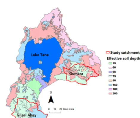
Figure 1. The Upper Blue Nile Basin and the Lake Tana sub-basin (a) and the study catchments and the gauging stations in the Lake Tana
sub-basin georeferenced on the SRTM DEM (b).
Figure 2. The modeling approach showing (a) divisions of a catchment into different runoff production areas; (b) conceptual model
configu-ration of the soil surface at an outlet of a catchment; and (c) inflows and outflows for the soil reservoir when the soil water storage capacity is (i) below field storage capacity (ii) greater than field storage capacity and (iii) greater than the maximum soil water storage (after Krasnostein and Oldham, 2004).
medium slope and flat surfaces as
S(t )=S(t−1t )+(P+Qr−Ea−Qss−Qse1−R)1t. (3) 3.1 Actual evapotranspiration
During wet periods, when the depth of available water ex-ceeds the maximum available soil storage capacity (Sb, in mm), the actual evapotranspiration is equal to the potential evapotranspiration (Ep, in mm day−1). WhenS(t )is lower than Sb, Ea is assumed to decrease linearly with moisture content as follows (Steenhuis and van der Molen, 1986):
Ea=Ep( S(t )
Sb
), (4)
Sb=Dφ, (5)
whereDis the soil depth [mm] andφis the soil porosity (-).
3.2 Subsurface runoff
Subsurface runoff,Qss [mm day−1], occurs only when the storage depth exceeds the field storage capacity (Sf, in mm). It is calculated as the difference between the storage and the field storage capacity, divided by the response time (Tr)of the catchment with respect to subsurface flow (Jothityangkoon et al., 2001):
Qss=
S(t )−Sf Tr
when S(t ) > Sf, (6)
Qss=0 when S(t )≤Sf. (7)
The field storage capacity of the soil reservoir,Sf [mm], is calculated using
Sf=FcD, (8)
[image:4.612.81.519.316.429.2]The catchment response time is the time taken by the ex-cess water in the soil to be released from the soil and drained out from the catchment. This response time depends on the properties of the soil and the topography of the system, and the subsurface flow velocity (Vb, in mm day−1) can be ex-pressed as
Vb= L Tr
, (9)
whereLis the average slope length of the catchment [mm]. From Darcy’s law in saturated soils,Vbis also given as
Vb=Ksi, (10)
whereKs is the saturated hydraulic conductivity of the soil [mm day−1] andiis the hydraulic gradient, which is approx-imated by the average slope gradient (G)of the catchment.
Brooks et al. (2004) analyzed the variability of saturated hydraulic conductivity with depth and found largeKsvalues near the surface or root zone layer and the transmissivity that decreases exponentially with depth. Accordingly, a variation is made between the upper soil layer (which affects inter-flow) and deep soil layer (percolation to groundwater) hy-draulic conductivities. The permeability (K, in mm day−1) of the upper soil layer for the interflow under different soil water conditions is modeled as
K=Ks,u(1−e −βS(t )S
b ), (11)
whereβ is a dimensionless parameter andKs,u[mm day−1] is the saturated hydraulic conductivity of the upper soil layer, both of which are to be calibrated.
The response time (Tr)in Eq. (6) is hence approximated from Eqs. (9), (10) and (11) as
Tr= L
G K, (12)
whereLandKare as defined in Eqs. (9) and (11) andGis average slope gradient of the catchment.
The deep percolation or recharge to groundwater (R, in mm day−1) under varying soil water content conditions is modeled as
R=Ks,e(1−e −γS(t )S
b ), (13)
whereγ a dimensionless parameter, andKs,e[mm day−1] is the saturated hydraulic conductivity of the deep soil layer, which is to be estimated from the aquifer properties of the catchments. This equation is identical to Eq. (11); therefore in both cases it is assumed that conductivities vary exponen-tially under varying soil water content conditions but with different magnitudes.
3.3 Saturated excess runoff
[image:5.612.310.546.65.255.2]Saturated excess runoff or surface runoff (Qse1, in mm day−1) is calculated as the depth of water that exceeds
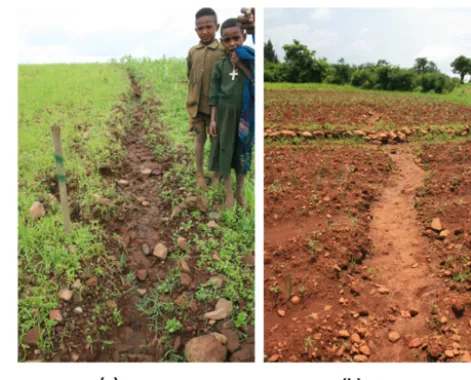
Figure 3. Typical surfaces with poor infiltration on hillslopes in
the Gumara catchment: (a) shallow soil overlying bedrock and (b) plough pan with typical plough marks. The occurrence of high runoff response on these surfaces is evidenced by the presence of rill erosion (photos: Elise Monsieurs).
the total water storage in the soil reservoir at each time step (Jothityangkoon et al., 2001; Krasnostein and Oldham, 2004).
Qse1 =
S(t )−Sb
1t when S(t ) > Sb
Qse1 =0 when S(t )≤Sb
(14)
3.4 Surface runoff from the impermeable areas
Field visits on the Upper Blue Nile Basin (including the study catchments) revealed the existence of exposed surfaces that cause strong runoff response. These are areas with little or no soil cover and bedrock outcropping in some parts of the catchment as well as soils with well-developed tillage pans (Temesgen et al., 2012a, b) (Fig. 3). Hence, runoff from these almost impermeable areas is modeled as infiltration excess (Hortonian flow) runoff with a very small amount of reten-tion before runoff occurs (Steenhuis et al., 2009). The surface runoff from these areas (QSe2, in mm day−1) is calculated as
QSe2 =P−Ep when P > Ep
QSe2 =0 when P ≤Ep, (15)
whereP andEp[mm day−1] are as defined above. The im-permeable portion of the catchment area (Ar, in km2)is mod-eled from the total catchment area (At, in km2)as
Ar=λAt, (16)
3.5 Groundwater reservoir and baseflow
The introduction of a deep groundwater storage (Fig. 2b) helps to improve low-flow predictions. This baseflow reser-voir is assumed to act as a nonlinear reserreser-voir (Wittenberg, 1999) and its outflow,Q2[mm day−1], and storage,Sg[mm], are related as
Q2= Sg(t )k1
1t , (17)
wherek1is a dimensionless model parameter. The water bal-ance of the slow-reacting reservoir (groundwater reservoir) is given by
Sg(t )=Sg(t−1t )+(R−Q2)1t, (18) whereSg(t )[mm] is the groundwater storage at the given time step, Sg(t−1t ) [mm] is the previous time step groundwater storage andR [mm day−1] is the deep percolation, as given by Eq. (13).
In total the model has seven parameters:
i. Parameters for the recharge (α1 andα2): in the three slope classifications,α1is to consider for the recharge from the steep slope into the medium slope surface and
α2 is for the recharge from the medium slope surface into the flat surface. There is no parameter for the steep slope surface since there is no surface that recharges it. Therefore, there are two parameters for the three slope classifications.
ii. Parameter for the impermeable surface of the catchment (λ): the catchment is divided into two surfaces (imper-meable surface with no or little soil cover and the soil surface). The parameterλis introduced to represent the fraction of impermeable surface within the total catch-ment and this part of the catchcatch-ment is not classified as steep, medium slopes and flat surfaces since the classi-fication of this part of the catchment into such classes is not important. Thus we have one parameter.
iii. The parametersβ,γ,k1andKs,u: the parametersβand γ are introduced to account variability of permeability and deep percolation of soil with soil water storage.k1 relates discharge and storage for the ground water and
Ks,uis the saturated hydraulic conductivity in the upper soil layer. We assumed that these parameters are less influenced by topography and each model parameter is assumed to be same for each slope classification of the catchment. Moreover, it is quite inconsistent to sepa-rate the groundwater system in the catchment. There-fore, all the three slope-based classified sub-catchments share the same groundwater reservoir.
In this modeling approach, stream–groundwater interactions are assumed to be minimal and the groundwater is assumed
to recharge the streams from deep percolation of rainfall on the catchments that produces baseflow of the rivers/streams. The storage effect of the streams when considered on the ba-sis of average daily flows of the streams is assumed to be negligible and hence streamflow routing was not considered for such smaller streams.
3.6 Total river discharge
The total river discharge (Qt, in mm day−1) at the outlet of the catchments is given by
Qt=Qss+Qse1+QSe2+Q2. (19)
4 Data inputs
The data needed for the model are classified into three types: topographical, soil and hydrological data.
4.1 Topographical data
Steenhuis et al. (2009) found that overland flow in the Blue Nile Basin is generated from saturated areas in the relatively flatter areas and from bedrock areas, while in the rest of the catchment all the rainfall infiltrates and is lost subse-quently as evaporation, interflow or baseflow. Topographical processes have been found to be the dominant factors in af-fecting runoff in the Blue Nile Basin (Bayabil et al., 2010). We used topography of catchments as the main criterion to divide the catchment into different runoff production sur-faces. Based on slope criteria (FAO, 2006), each study catch-ment was divided into three sub-catchcatch-ments as steep (slope gradient>30 %), hilly or medium (slope gradient between 8 and 30 %) and flat (slope gradient<8 %) to consider spa-tial variability in catchment properties and runoff generation mechanisms (Fig. 4).
The 30 m×30 m resolution global digital elevation model (GDEM) was used to define the topography (downloaded from the ASTER website, http://earthexplorer.usgs.gov/). The GDEM (Fig. 1b) was used to delineate and calculate the average slope gradient and average slope length of the catch-ments (topography-related inputs to the model).
4.2 Soil data
The model requires data on depth, porosity and field capacity of the soils. Soil depth and soil types data (Figs. 5 and 6) were obtained from the Abay River basin integrated master plan study BCEOM (1998).
Figure 4. The three slope categories for the Gilgel Abay and Gumara catchments.
Figure 5. Major soil types in the Lake Tana Basin and the study
catchments (source: BCEOM, 1998).
The saturated hydraulic conductivity for the deep percola-tion (Eq. 12) was estimated using ranges of conductivities given by Domenico and Schwartz (1990) for the saturated hydraulic conductivities of a deep soil layer (colluvial mantle on top of the igneous rock). A summary of the topographic, soil and saturated hydraulic conductivity data for the study catchments is provided in Table 1.
4.3 Weather data
Daily precipitation is the key input meteorological data for the model. Other meteorological data like minimum and maximum air temperature, humidity, wind speed and dura-tion of sunshine hours were also used to calculate the poten-tial evapotranspiration, the other input variable to the model. All weather data were obtained from the Ethiopian Na-tional Meteorological Agency (NMA) for 13 stations located
Figure 6. Soil depth in the Lake Tana Basin and the study
catch-ments (source: BCEOM, 1998).
[image:7.612.53.286.252.465.2]Table 1. Input data on topography, soil and saturated hydraulic conductivities for the study catchments as classified into different hydrological
regimes using topography.
Coverage Average Saturated
from the soil Dominant hydraulic
Slope Average total area depth soil Field conductivity
Catchment class slope (%) (%) (m) texture Porosity capacity Ks,e(m s−1)
Gilgel Abay
level (≤8 %) 3.4 54 0.92 clay 0.46 0.36
9.26×10⁻⁸ hilly (8 %<slope≤30 %) 15.9 38 1.29 clay to clay loam 0.42 0.32
steep (>30 %) 41.4 8 1.49 clay loam to silt loam 0.4 0.26
Gumara
level (≤8 %) 4.0 24 1.5 clay 0.46 0.36
1.16×10⁻⁸ hilly (8 %<slope≤30 %) 17.2 60 1.24 loam , silty clay 0.42 0.26
[image:8.612.47.289.105.419.2]steep (>30 %) 41.5 16 1.2 sandy loam 0.25 0.1
Figure 7. Location map of rainfall stations for the study catchments.
4.4 River discharge
Starting from July 2011, water level was measured at the Wanzaye station (11.788073◦N, 37.678266◦E) on the Gu-mara River and from December 2011 at the Picolo station (11.367088◦N, 37.037497◦E) on the Gilgel Abay River. The water level measurements were made using mini-divers, au-tomatic water level recorders (every 10 min), and manual readings from a staff gauge (three times a day, at 07:00, 13:00 and 18:00), following the procedures described by Amanuel et al. (2013).
Discharges were computed from the water levels using rating curves (Eqs. 21 and 22) for each station. The rating curves (Fig. 8) were calibrated based on detailed surveys of the cross sections of the rivers and measurements of flow ve-locity at different flow stages, using the following commonly used expression:
Q=ahb, (20)
wherea andbare fitting parameters and Q[m3s−1] andh
[m] are discharge and water level, respectively. The
result-ing ratresult-ing curve equation for the Gumara catchment at the gauging station (Wanzaye station) is
Q=44.1h1.965(R2=0.997, n=12), (21) and that of the Gilgel Abay catchment at the Picolo station is
Q=70.39h2.105(R2=0.985, n=14) . (22)
Compared to the discharge data that have been gathered in the past, the discharge data that are acquired for this study are of superior quality, since a high time resolution during the measurement has been used. This minimizes the risk of missed peaks, particularly during the night. Furthermore, fre-quent supervision was also conducted during the data collec-tion campaign. Hence, these data were used for the model calibration. Discharge data collected before December 2011 were obtained for nearby stations from the Hydrology De-partment of the Ministry of Water Resources of Ethiopia, which has a long data record (since 1960) for these sta-tions. However, the latter measurements were made using staff gauge readings twice a day, with many data gaps and discontinuities, particularly at the end of the observation win-dow. The discharge data from 2000 to 2005 are relatively bet-ter and are used to validate the model.
The 2012 discharge data for Dirma catchment (outlet at 12.427194◦N, 37.326209◦E), collected in the same way as those of Gilgel Abay and Gumara, were used to assess the transferability of the model parameters.
5 Calibration and validation
Figure 8. Stage–discharge relationship (rating curves) for Gilgel Abay at Picolo and Gumara at Wanzaye stations.
technique inspired by social behavior of bird flocking or fish schooling (Kennedy and Eberhart, 1995). The advantages of PSO are that the algorithm is easy to implement and that it is less susceptible to getting trapped in local minima (Scheer-linck et al., 2009). We carried out 50 iterations and 50 repeti-tions, in total 2500 runs for each catchment to search for the optimal value of the model parameters (Table 2) and 30 parti-cles were used in the PSO. The criterion in the search for the optimal value was to minimize the root-mean-squared error (RMSE) as the objective function, given by
RMSE= v u u u t n P i=1
(Qobs,i−Qsim,i)2
n , (23)
whereQobsis observed discharge [mm day−1],Qsimis simu-lated or modeled discharge [mm day−1] andnis the number of data points. The parameter values corresponding to the minimum “RMSE” were considered as optimum. From the optimal model parameters, the performance of the model was also evaluated using (i) the Nash–Sutcliffe efficiency (NSE) according to Nash and Sutcliffe (1970) and (ii) the coefficient of determination (R2):
NSE=1−
n
P
i=1
(Qsim,i−Qobs,i)2
n
P
i=1
(Qobs,i−Qobs)2
, (24)
R2= n P
i=1
(Qsim,i−Qsim)(Qobs,i−Qobs)
s n P
i=1
(Qsim,i−Qsim)2 s
n P
i=1
(Qobs,i−Qobs)2 2 , (25)
whereQobs[mm day−1] andQsim[mm day−1] are the mean observed and simulated discharges, respectively.
Percent bias (PBIAS) is used as an additional model per-formance indicator. It measures the average tendency of the simulated data to be larger or smaller than the observa-tions (Gupta et al., 1999). The optimal value of PBIAS is 0, with lower absolute values indicating better model
simu-lation (positive values indicate overestimation, whereas neg-ative values indicate model underestimation bias).
PBIAS=
n
P
i=1
(Qsim,i−Qobs,i)
n
P
i=1 Qobs,i
∗100 % (26)
The impacts of model parameters on the output of the model when their values are different from the calibrated op-timal values were evaluated with respect to the RMSE for Gumara catchment. The sensitivity analysis was made by randomly selecting parameter values in the region of the opti-mal values obtained from PSO and calculating NSE for each selected value. The applicability of the model to other un-gauged catchments outside the study catchments in the Lake Tana Basin was also tested using direct parameter transfer-ability.
6 Soil and Water Assessment Tool (SWAT) and (FlexB) models as benchmarks for comparison with
Wase–Tana model
The two models are used as benchmark models to assess the performance of the model of this paper (hereafter referred to as the Wase–Tana model, in favor of the project name that funded this study), which tries to use all available informa-tion and considers topography as a good proxy for the vari-ability of most of the catchment characteristics in the Upper Blue Nile Basin.
6.1 SWAT model
SWAT is a basin-scale and continuous-time model used to simulate the quality and quantity of surface and ground water and predict the environmental impact of land use, land man-agement practices and climate change (Arnold et al., 1998). The hydrological model is based on the water balance equa-tion
SWt=SW0+ t
X
i=1
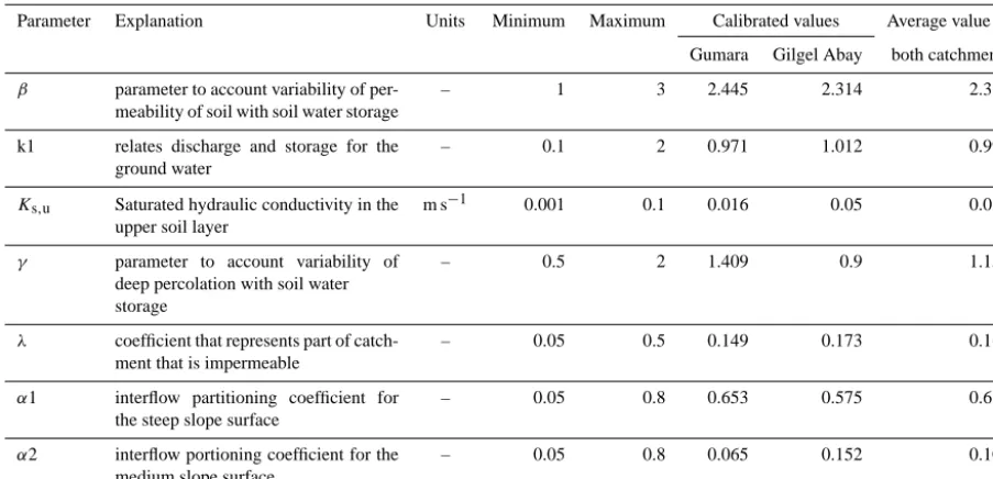
Table 2. Model parameters, their ranges, and calibrated values found in 2500 iterations in the PSO calibration.
Parameter Explanation Units Minimum Maximum Calibrated values Average value of
Gumara Gilgel Abay both catchments
β parameter to account variability of per-meability of soil with soil water storage
– 1 3 2.445 2.314 2.380
k1 relates discharge and storage for the ground water
– 0.1 2 0.971 1.012 0.992
Ks,u Saturated hydraulic conductivity in the upper soil layer
m s−1 0.001 0.1 0.016 0.05 0.033
γ parameter to account variability of deep percolation with soil water storage
– 0.5 2 1.409 0.9 1.155
λ coefficient that represents part of catch-ment that is impermeable
– 0.05 0.5 0.149 0.173 0.161
α1 interflow partitioning coefficient for the steep slope surface
– 0.05 0.8 0.653 0.575 0.614
α2 interflow portioning coefficient for the medium slope surface
– 0.05 0.8 0.065 0.152 0.109
where SWt is the soil water content at timet [mm]; SW0is the initial soil water content [mm];1tis the time step (day) andRi,Qi, ETi,Pi and QRi are the daily amounts of pre-cipitation, runoff, evapotranspiration, percolation and return flow [mm day−1], respectively.
In SWAT, a watershed is divided into homogenous hy-drologic response units (HRUs) based on elevation, soil, management and land use, whereby a distributed parameter such as hydraulic conductivity is potentially defined for each HRU. Hence, an analyst is confronted with the difficult task of collecting or estimating a large number of input parame-ters, which are usually not available for regions like the Up-per Blue Nile Basin. Details of the model can be accessed at the SWAT website (http://swatmodel.tamu.edu).
Automatic calibration and validation of the model was made using SWAT-CUP. It is an interface that has been devel-oped for SWAT automatic calibration and model uncertainty analysis (Abbaspour et al., 2007). R2 and NSE were used as objective functions during the calibration process of the search for the optimal value.
6.2 FlexBmodel
This model is a lumped conceptual type and is character-ized by three reservoirs as described by Fenicia et al. (2008): the unsaturated soil reservoir (UR), the fast-reacting reser-voir (FR) and the slow-reacting reserreser-voir (SR). The model has eight parameters: a shape parameter for runoff genera-tion β [-], the maximum UR storage Sfc [mm], the runoff partitioning coefficientD[-], the maximum percolation rate
Pmax [mm h−1], the threshold for potential evaporation Lp [-], the lag times of the transfer functionsNlag [h], and the timescales of FR and SR: Kf [h] andKs [h]. Details of the
model and the various equations of the model can be found in Fenicia et al. (2008).
Calibration of this model was made using the PSO tech-nique, following similar procedures of the Wase–Tana model calibration algorithm. The same objective function, RMSE, is also used in the search for the optimal value.
7 Results and discussion
7.1 The daily hydrograph and model performance 7.1.1 Wase–Tana model performance
Figures 9 and 10 show a comparison of the modeled with the observed discharge data for the two study catchments and for both the calibration and validation periods.
Despite the possible spatial variability of some input data (average soil and rainfall data are considered) and the sim-plicity of the model, discharge is reasonably well simulated during both the calibration and validation periods. This can be seen from the visual inspection of the hydrographs and from the model performance indicators (Table 3).
Figure 9. Comparison of predicted and observed discharge and precipitation of the Gumara and the Gilgel Abay catchments for the calibration
period.
Figure 10. Predicted and observed discharges and precipitation of the Gumara and the Gilgel Abay catchments for the validation period.
models. Initially, the soils are relatively dry and most of the rainfall during the beginning of the rainy season is not ef-fective to produce runoff in the model as the soil reservoir has to be filled first to generate the faster component of the runoff. Besides model uncertainties, the rainfall data quality can also affect the model performance, mainly in the case of the Gilgel Abay catchment. TheR2values for the time series of daily streamflow between simulated and observed values were from 0.80 to 0.86 for the Gumara catchment, and from
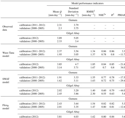
[image:11.612.114.481.346.564.2]Table 3. Statistical comparison and model performance of the modelled and observed river discharge (Q) for the two catchments.
Model performance indicators
Standard
MeanQ Deviation RMSE1
[mm day−1] [mm day−1] [mm day−1] NSE2∗ R2 PBIAS3
Observed data
Gumara
calibration (2011–2012) 2.31 3.79 – – – –
validation (2000–2005) 2.3 3.75 – – – –
Gilgel Abay
calibration (2012) 3.89 5.05 – – – –
validation (2000–2005) 2.33 3.4 – – – –
Wase-Tana model
Gumara
calibration (2011–2012) 2.37 3.56 1.34 0.86 0.86 3.30
validation (2000–2005) 1.95 3.05 1.37 0.78 0.8 −11.75
Gilgel Abay
calibration (2012) 3.85 4.7 1.85 0.84 0.85 −21.61
validation (2000–2005) 3.14 3.71 1.67 0.7 0.8 34.06
SWAT model
Gumara
calibration (2011–2012) 1.91 3.33 1.55 0.77 0.78 −17.50
validation (2000–2005) 1.62 3.11 1.63 0.72 0.75 −29.48
Gilgel Abay
calibration (2012) 2.02 3.20 1.40 0.60 0.79 −44.01
validation (2000–2005) 2.45 3.86 2.30 0.55 0.63 5.45
FlexB model
Gumara
calibration (2011–2012) 2.43 3.64 1.54 0.82 0.82 5.30
validation (2000–2005) 2.01 3.35 1.47 0.80 0.81 −12.67
Gilgel Abay
calibration (2012) 3.81 4.03 1.62 0.80 0.84 5.64
validation (2000–2005) 4.13 4.33 2.15 0.50 0.75 77.67
1. RMSE: Root Mean Squared Error as defined in Eq. (23). 2*. NSE: Nash–Sutcliffe Efficiency as defined in Eq. (24). 3. PBIAS: Percentage Bias as defined in Eq. (26).
to mention some for the model inputs. Hence, this averaged condition may be one source of error such that the model may not exactly mimic extremes like peak discharges. 7.1.2 Performance in comparison with the
benchmark models
For the calibration period, almost all the three models per-formed quite well (Table 3). However, an appreciable de-crease in model performance has been noticed for the vali-dation period in Gilgel Abay catchment for the benchmark models. SWAT is a physically based complex model, requir-ing extensive input data, which is a challenge for data-scarce regions like the Upper Blue Nile Basin. The model simu-lations can only be as accurate as the input data. This sug-gests that the coarser data input used for the model in the study catchments might have significantly affected the
cali-bration and consequently the validation simulations. On the other hand, the likely reason for decreased performance of the FlexBmodel for the Gilgel Abay catchment is the over-simplification of the catchment heterogeneity, since it is a lumped one and the impact is greater when the catchment be-comes larger (Gilgel Abay catchment is larger than Gumara catchment).
A look at the flow duration curves (Figs. 11 and 12) in-dicates the higher uncertainty of the two benchmark models (mainly SWAT model) with respect to low-flow predictions.
Figure 11. Predicted and observed flow duration curves of the Gumara and the Gilgel Abay catchments for the calibration period.
Figure 12. Predicted and observed flow duration curves of the Gumara and the Gilgel Abay catchments for the validation period.
model structure and use of all available information on hy-drology based on topography is a good choice for the Upper Blue Nile Basin. From a comparison of four model structures on the Upper Heihe in China, Gao et al. (2014) also con-firmed that topography-driven model reflects the catchment heterogeneity in a more realistic way.
7.2 The hydrograph components and hydrological response of the catchments
[image:13.612.134.460.333.546.2]sum ofQse1 and QSe2), interflow or subsurface flow (Qss) and baseflow (Q2)components of the total daily hydrograph computed by the model for the calibration and validation pe-riods are given in Table 4.
The total mean annual runoff generated by the model is in line with the observations for both catchments in the cal-ibration period (Table 4), while an appreciable difference is noticed in the values for the Gilgel Abay catchment in the validation period. One of the problems in accurate model-ing of the discharge is that precipitation measurements do not cover well the catchments. This is particularly the case for the Gilgel Abay catchment, where the rainfall stations are poorly distributed as most of the meteorological stations lie near the water divides. The calibration results are better, since the data from the recently established precipitation sta-tions (e.g., Durbetie) could be used. There are also doubts about the representativeness of the discharge data used for the validation of the model, because the water level measure-ments were made manually and twice daily (in the morning and late afternoon), leading to the possibility of missing flash floods at other moments of the day as the stream discharge is very variable. This can be clearly seen from the mean annual observed flows during the calibration and validation periods for Gilgel Abay. The mean annual observed flow in the val-idation period was found to be much smaller than the cor-responding flow during the calibration period (Table 4). The closer total mean annual runoff values and the better model performance indicators for the Gumara catchment during the calibration period suggest that the model can perform satis-factorily with better input discharge and precipitation data.
From PBIAS results (Table 3), the FlexB model showed overestimated bias and the SWAT model behaved the oppo-site for both catchments during the calibration period.
[image:14.612.310.545.67.224.2]Despite the variations in mean annual runoff generated by the Wase–Tana model, the partitioning of the total runoff into the different components (Table 4) in each period is almost identical for each catchment, as expected. About 65 % of the runoff appears in the form of interflow for the Gumara catch-ment, and baseflow takes the larger proportion for Gilgel Abay catchment (44–48 %). Uhlenbrook et al. (2010) found the baseflow to be about 32 % from similar model study re-sults for Gilgel Abay catchment. Vogel and Kroll (1992) have shown that baseflow is a function of catchment area, and ge-omorphological, geological and hydrogeological parameters of the catchment have a linear incidence on the discharges. The difference between the baseflow of the two catchments is high, despite their comparable catchment sizes, suggesting rather the different structure, functioning and hydrodynamic properties of the two catchments. Hence, the model results reveal that the groundwater in the Gilgel Abay catchment receives more recharge and makes a greater contribution to the river flow. This is in line with Kebede (2013) and Poppe et al. (2013), who showed that the largest part of the Gilgel Abay catchment consists of pumice stones and fractured qua-ternary basalts with a high infiltration capacity and hydraulic
Figure 13. One of the springs in Gilgel Abay catchment used as a
water supply source for Bahir Dar.
properties, which clarifies the large groundwater potential. In line with this, several large springs exist in the catchment, in-cluding one that is used as a source of water supply for the city of Bahir Dar (Fig. 13).
The other interesting result is that direct runoff is the smallest fraction of the total runoff for both catchments (18– 19 % for Gumara and 20 % for Gilgel Abay) and almost all peak flow incidences are associated with direct runoff. More than 90 % of this direct runoff is found to be from the rel-atively impermeable (degraded areas, plough pans or rock outcrops with little or no soil cover) surfaces. The calibrated result shows that this type of runoff production area covers 15 % of the Gumara and 17 % of the Gilgel Abay catchments, respectively. In a similar study, Steenhuis et al. (2009) men-tion that the rock outcrops occupy 20 % of the total catch-ment area in the Abay (Blue Nile) catchcatch-ment at the Ethiopia– Sudan border upstream of the Rosaries Dam, which is very similar to the result of Gilgel Abay catchment in this study.
Table 4. Model results on the hydrograph components of the catchments.
Runoff components Unit For the calibration period For the validation period
Gumara Gilgel Abay Gumara Gilgel Abay
Total mean annual runoff predicted (Qpr) mm year−1 864 1405 713 1146
Total mean annual runoff observed (Qob) mm year−1 843 1420 841 938
Mean annual surface runoff (Qse) mm year−1 161 280 129 234
% from the totalQpr 19 20 18 20
Mean annual interflow (Qss) mm year−1 574 508 458 369
% from the totalQpr 66 36 64 32
Mean annual baseflow (Q2) mm year−1 128 617 126 548
[image:15.612.64.532.85.241.2]% from the totalQpr 15 44 18 48
Figure 14. Local model parameter sensitivity analysis for Gumara
catchment. Parameters are explained in Table 2.
7.3 Transferability of model parameters to other ungauged catchments and sensitivity
The sensitivity analysis was performed on model parameters for Gumara catchment with respect to the RMSE.
The parameters β,α1 and γ show poor sensitivity for a wide range of values with respect to the local sensitivity anal-ysis. The local sensitivity analysis shows the sensitivity of a variable to the changes in a parameter if all other parameters are kept constant at some value (optimal value in this case). An increase in the value ofβ beyond 1.4 showed almost no sensitivity, while the model efficiency decreased slightly af-ter an increase in the value of γ from the optimum. This means that there is little confidence in the model’s correspon-dence with these parameters and that the parameters can be
reduced without appreciable impact on the model (Fenicia et al., 2008). k1,Ks,uandλare very sensitive parameters in this model and the model performance drops abruptly if the parameters exceed a particular threshold value (Fig. 14).
The global sensitivity analysis (Fig. 15), however, shows interactions among all the input parameters of the model. Al-though global sensitivity analysis reveals details of the model behavior in a more general sense through random parame-ter sampling and that the parameparame-ters are all sensitive, the lo-cal sensitivity analysis indicates that moderate variations in the parameter values for some parameters can still drastically change the model performance.
The model parameter transferability to other ungauged catchments in the basin has been tested by analyzing the variability among the calibrated parameters of the two catch-ments. Table 2 shows that the calibrated parameters are nearly identical for both catchments, except for γ and λ, which are related to deep percolation and impermeable frac-tion of the catchment, respectively. As described above, they affect the baseflow and direct runoff contributions to the to-tal river flow. However, we showed that the contributions of these components to the total runoff are relatively small and
[image:15.612.50.286.244.480.2]fur-Figure 15. Global model parameter sensitivity analysis results for Gumara catchment. Parameters are explained in Table 2.
Table 5. Comparison of model performance between the optimal and average model parameters of the three catchments.
Model performance for the
Model performance for the average of the parameters of
Catchment optimal model parameters optimal model the two catchments
RMSE RMSE
[mm day−1] NSE R2 [mm day−1] NSE R2
Gumara calibration period 1.34 0.86 0.86 1.48 0.84 0.86
validation period 1.37 0.78 0.80 1.82 0.76 0.77
Gilgel Abay calibration period 1.85 0.84 0.85 1.98 0.83 0.84
validation period 1.67 0.70 0.80 1.93 0.68 0.78
Dirma for the 2012 discharge – – – 1.79 0.58 0.60
ther in the future, involving more catchments and more years of data.
In general, transferability results showed good perfor-mance of the daily runoff model in the two study catchments and an average performance in the test catchment (Dirma catchment). This can be explained by the fact that effort was made to incorporate more knowledge in the model structure to increase model realism. We based our model strongly on the soil storage characterization of the soil reservoir in the rainfall–runoff process and representation of the maximum storage of the unsaturated reservoir at the catchment scale, which is closely linked to rooting depth and soil structure and strongly depends on the ecosystem. Transferability of the model has benefited from this in that we were able to derive most of the input data from the test catchments. The consideration of topography-driven landscape heterogeneity analysis and catchment information extraction based on to-pography (slope) for the model is another reason for the bet-ter performance of the model transferability. The role of to-pography in controlling hydrological processes and its link-age to geology, soil characteristics, land cover and climate through coevolution have been indicated in different
stud-ies (Sivapalan, 2009; Savenije, 2010; Gao et al., 2014). The results suggest the possibility of directly using the average model parameter values for other ungauged catchments in the basin, even though further tests on such catchments are still recommended. However, we believe that this is a useful result for operational management of water resources in this data-scarce region.
8 Conclusions
[image:16.612.88.503.291.427.2]runoff production. The permeable surfaces were further di-vided into three subgroups using topographic criteria such as flat, medium, and steep slope areas. The rainfall–runoff pro-cesses were represented by two reservoirs (soil and ground-water reservoirs) and the ground-water balance approach was used to conceptualize the different hydrological processes in each of the two reservoirs. Such a detailed form of modeling, using topography as a dominant landscape characteristic to classify a catchment into different hydrological regimes, has not been applied yet in the Upper Blue Nile, Lake Tana sub-basin.
We demonstrated that the model performs well in simulat-ing river discharges, irrespective of the many uncertainties. Model validation indicated that the Nash–Sutcliffe values for daily discharge were 0.78 and 0.7 for the Gumara and Gilgel Abay catchments, respectively.
We were able to partition the total runoff into a fast com-ponent (direct runoff and interflow) and a slow comcom-ponent (baseflow) and estimated the contributions of each compo-nent for the catchments. About 65 % of the runoff appears in the form of interflow for the Gumara catchment, and base-flow is responsible for the larger proportion of the discharge for the Gilgel Abay catchment (44–48 %). Direct runoff gen-erates the lower fraction of runoff components in both catch-ments (18–19 % for the Gumara and 20 % for the Gilgel Abay) and almost all peak flow incidences are associated with direct runoff. More than 90 % of this direct runoff is found to be from the relatively impermeable (plough pan or rock outcrops with little or no soil cover) source areas. The hillslopes (medium and steep slope source areas) are recharge areas (sources of interflow and deep percolation) and generated almost no direct runoff as saturated excess flow.
The results of this study, with comparisons to two bench-mark models, clearly demonstrate that topography is a key landscape component to consider when analyzing runoff pro-cesses in the Upper Blue Nile Basin. Generally, runoff in the basin is generated both as infiltration and saturation excess runoff mechanisms. A considerable portion of the landscape in the Upper Blue Nile Basin consists of impermeable rock outcrops and hard soil surfaces (15–17 % of the total catch-ment area as per the results of this study) and they are the sources of most of the direct runoff. This conceptual model, developed to study the runoff processes in the Upper Blue Nile Basin, may help to predict river discharge for ungauged catchments for a better operation and management of wa-ter resources in the basin, owing to its simplicity and parsi-monious nature with respect to parameterization. The runoff processes in the basin are also found to be affected much by the rainfall, as the performance of the model was better for those study catchments where coverage of rainfall stations was good. Hence a better spatial and temporal resolution of rainfall data is required to further improve the model perfor-mance and to further enhance the understanding of the runoff processes in the basin.
Acknowledgements. We wish to acknowledge the efforts of the field staff and data collectors for their help during the installation of monitoring stations and data recording. We thank the project staff and MSc students for the logistic help and valuable field inputs. We are grateful to the Ministry of Water and Energy and National Meteorological Agency of Ethiopia for making data available. This research was supported by the Belgian Development Cooperation (VLIR-UOS, WASETANA project).
Edited by: R. Merz
References
Abbaspour, K. C., Yang, J., Maximov, I., Siber, R., Bogner, K., Mieleitner, J., Zobrist, J., and Srinivasan, R.: Modelling hydrol-ogy and water quality in the pre-alpine/alpine Thur watershed using SWAT, J. Hydrol., 333, 413–430, 2007.
Allen, R. G., Pereira, L. S., Raes D., and Smith, M.: Crop evapotran-spiration. Guide- lines for computing crop water requirements, FAO Irrigation and Drainage Paper 56, FAO, Rome, 1998. Antar, M. A., Elassiouti, I., and Allam, M. N.: Rainfall-runoff
mod-eling using artificial neural networks technique: a Blue Nile catchment case study, Hydrol. Process., 20, 1201–1216, 2006. Arnold, J. G., Srinivasin, R., Muttiah, R. S., and Williams, J. R.:
Large Area Hydrologic Modeling and Assessment: Part I. Model Development, JAWRA J. Am. Water Resour. Assoc., 34, 73–89, 1998.
Bayabil, H. K., Tilahun, S. A., Collick, A. S., and Steenhuis, T. S.: Are runoff processes ecologically or topographically driven in the Ethiopian Highlands? The case of the Maybar, Ecohydrology, 3, 457–466, doi:10.1002/eco.170, 2010.
BCEOM: Abay River Basin Integrated Development Master Plan – Phase 2 – Land Resources Development – Reconnaissance Soils Survey, Ministry of Water Resources: Addis Ababa, 208 pp., 1998.
Beven, K.: On landscape space to model space mapping, HP today, Hydrol. Process., 15, 323–324, 2001.
Bitew, M. M. and Gebremichael, M.: Assessment of satellite rainfall products for streamflow simulation in medium watersheds of the Ethiopian highlands, Hydrol. Earth Syst. Sci., 15, 1147–1155, doi:10.5194/hess-15-1147-2011, 2011.
Brooks, E. S., Boll, J., and McDaniel, P. A.: A hillslope-scale exper-iment to measure lateral saturated hydraulic conductivity, Water Resour. Res., 40, W04208, doi:10.1029/2003WR002858, 2004. Collick, A. S., Easton, Z. M., Ashagrie, T., Biruk, B., Tilahun, S.,
Adgo, E., Awulachew, S. B., Zeleke, G., and Steenhuis, T. S.: A simple semidistributed water balance model for the Ethiopian highlands, Hydrol. Process., 23, 3718–3727, 2009.
Conway, D.: A water balance model of the upper Blue Nile in Ethiopia, Hydrol. Sci., 42, 265–282, 1997.
Conway, D.: The Climate and hydrology of the Upper Blue Nile River, The Geographical J., 166, 49–62, 2000.
Dessie, M., Verhoest, N. E. C., Admasu, T., Pauwels, V. R. N., Poe-sen, J., Adgo, E., Deckers, J., and NysPoe-sen, J.: Effects of the flood-plain on river discharge into Lake Tana (Ethiopia), J. Hydrol., 519, 699–710, doi:10.1016/j.jhydrol.2014.08.007, 2014. Domenico, P. A. and Schwartz, F. W.: Physical and Chemical
Hy-drogeology, John Wiley & Sons, New York, p. 824, 1990. Fenicia, F., Savenije, H. H. G., Matgen, P., and Pfister, L.:
Understanding catchment behavior through stepwise model concept improvement, Water Resour. Res., 44, W01402, doi:10.1029/2006WR005563, 2008.
Food and Agriculture Organization of the United Nations, Rome (FAO): Guidelines for soil description, Rome, Italy, 2006. Frankenberger, J. R., Brooks, E. S., Walter, M. T., Walter, M. F., and
Steenhuis, T. S.: A GIS-Based Variable Source Area Hydrology Model, Hydrol. Process., 13, 804–822, 1999.
Gao, H., Hrachowitz, M., Fenicia, F., Gharari, S., and Savenije, H. H. G.: Testing the realism of a topography-driven model (FLEX-Topo) in the nested catchments of the Upper Heihe, China, Hy-drol. Earth Syst. Sci., 18, 1895–1915, doi:10.5194/hess-18-1895-2014, 2014.
Gupta, H. V., Sorooshian, S., and Yapo, P.O.: Status of automatic calibration for hydrologic models: Comparison with multilevel expert calibration, J. Hydrologic Eng. 4, 135–143, 1999. Hurni, H.: Third Progress Report, Soil Conservation Research
Project, Vol. 4. University of Berne and the United Nations Uni-versity, Ministry of Agriculture, Addis Ababa, 1984.
Istanbulluoglu, E. and Bras R. L.: Vegetation-modulated land-scape evolution: Effects of vegetation on landland-scape processes, drainage density, and topography, J. Geophys. Res., 110, F02012, doi:10.1029/2004JF000249, 2005.
Johnson, P. A. and Curtis, P. D.: Water balance of Blue Nile River Basin in Ethiopia, J. Irrig. Drain. Eng. ASCE, 120, 573–590, 1994.
Jothityangkoon, C., Sivapalan, M., and Farmer, D. L.: Process con-trols of water balance variability in a large semi-arid catchment: downward approach to hydrological model development, J. Hy-drol., 254, 174–198, 2001.
Kebede, S., Travi, Y., Alemayehu, T., and Marc, V.: Water balance of Lake Tana and its sensitivity to fluctuations in rainfall, Blue Nile basin, Ethiopia, J. Hydrol., 316,233–247, 2006.
Kebede, S.: Groundwater in Ethiopia: Features, Numbers
and Opportunities, ISBN 3642303919, Springer, p. 297, doi:10.1007/978-3-642-30391-3, 2013.
Kennedy, J. and Eberhart, R.: Particle Swarm Optimization, Pro-ceedings of IEEE International Conference on Neural Networks, IV., 1942–1948, 1995.
Kim, U. and Kaluarachchi, J. J.: Application of parameter estima-tion and regionalizaestima-tion methodologies to ungauged basins of the Upper Blue Nile River Basin, Ethiopia, J. Hydrol., 362, 39–52, 2008.
Krasnostein, A. L. and Oldham, C. E.: Predicting
wet-land water storage, Water Resour. Res., 40, W10203,
doi:10.1029/2003WR002899, 2004.
Liu, B. M., Collick, A. S., Zeleke, G., Adgo, E., Easton, Z. M., and Steenhuis, T. S.: Rainfall-discharge relationships for a mon-soonal climate in the Ethiopian highlands, Hydrol. Process., 22, 1059–1067, 2008.
McWorter, D. B. and Sunada, D. K.: Groundwater Hydrology and hydraulics, Water Resources Publications, Ft. Collins. Co., 1997.
Mehta, V. K., Walter, M. T., Brooks, E. S., Steenhuis, T. S., Wal-ter, M. F., Johnson, M., Boll, J., and Thongs, D.: Application of SMR to modeling watersheds in the Catskill Mountains, Environ. Model. Assess., 9, 77–89, 2004.
Miserez, A.: Soil erodibility and mapping in different hydrologi-cal land systems of Lake Tana basin, Ethiopia, MSc thesis study, Department of Soil and Water Management, KULeuven, Leuven, Belgium, 2013.
Mishra, A., Hata, T., and Abdelhadi, A.W.: Models for recession flows in the upper Blue Nile River, Hydrol. Process., 18, 2773– 2786, 2004.
Mishra, A. and Hata, T.: A grid-based runoff generation and flow routing model for the upper Blue Nile Basin, Hydrol. Sci. J., 51, 191–206, 2006.
Nash, J. E. and Sutcliffe, J. V.: River flow forecasting through con-ceptual models part I: a discussion of principles, J. Hydrol., 10, 282–290, 1970.
Poppe, L., Frankl, A., Poesen, J., Teshager Admasu, Mekete Dessie, Enyew Adgo, Deckers, J., and Nyssen, J.: Geomorphol-ogy of the Lake Tana basin, Ethiopia, J. Maps, 9, 431–437, doi:10.1080/17445647.2013.801000, 2013.
Savenije, H. H. G.: HESS Opinions “Topography driven conceptual modelling (FLEX-Topo)”, Hydrol. Earth Syst. Sci., 14, 2681– 2692, doi:10.5194/hess-14-2681-2010, 2010.
Scheerlinck, K., Pauwels, V. R. N., Vernieuwe, H., and Baets, B. De.: Calibration of a water and energy balance model: Recursive parameter estimation versus particle swarm optimization, Water Resour. Res., 45, W10422, doi:10.1029/2009WR008051, 2009. Setegn, S. G., Ragahavan, S., and Bijan, D.: Hydrological modelling
in the Lake Tana Basin, Ethiopia using SWAT model, The Open Hydrol. J., 2, 49–62, 2008.
Sivapalan, M.: The secret to “doing better hydrological sci-ence”: Change the question!, Hydrol. Process., 23, 1391–1396, doi:10.1002/hyp.7242, 2009.
Steenhuis, T. S. and van der Molen, W. H.: The Thornthwaite-Mather procedure as a simple engineering method to predict recharge, J. Hydrol., 84, 221–229, 1986.
Steenhuis, T. S., Collick, A. S., Easton, Z. M., Leggesse, E. S., Bayabil, H. K., White, E .D., Awulachew, S. B., Adgo, E., and Ahmed, A. A.: Predicting discharge and erosion for the Abay (Blue Nile) with a simple model, Hydrol. Process. 23, 3728– 3737, 2009.
Tekleab, S., Uhlenbrook, S., Mohamed, Y., Savenije, H. H. G., Temesgen, M., and Wenninger, J.: Water balance modeling of Upper Blue Nile catchments using a top-down approach, Hy-drol. Earth Syst. Sci., 15, 2179–2193, doi:10.5194/hess-15-2179-2011, 2011.
Temesgen, M., Savenije, H. H. G, Rockström, J., and Hoogmoed, W. B.: Assessment of strip tillage systems for maize production in semi-arid Ethiopia: Effects on grain yield, water balance and water productivity, Phys. Chem. Earth, Parts A/B/C, 47–48, 156– 165, 2012a.
Tilahun, S. A., Guzman, C. D., Zegeye, A. D., Engda, T. A., Collick, A. S., Rimmer, A., and Steenhuis, T. S.: An effi-cient semi-distributed hillslope erosion model for the subhumid Ethiopian Highlands, Hydrol. Earth Syst. Sci., 17, 1051–1063, doi:10.5194/hess-17-1051-2013, 2013.
Uhlenbrook, S., Mohamed, Y., and Gragne, A. S.: Analyzing catch-ment behavior through catchcatch-ment modeling in the Gilgel Abay, Upper Blue Nile River Basin, Ethiopia, Hydrol. Earth Syst. Sci., 14, 2153–2165, doi:10.5194/hess-14-2153-2010, 2010. Vogel, R. M. and Kroll, C. N.: Regional geohydrologic-geomorphic
relationships for the estimation of low-flow statistics, Water Re-sour. Res., 28, 2451–2458, 1992.
Wale, A., Rientjes, T. H. M., Gieske, A. S. M., and Getachew, H. A.: Ungauged catchment contributions to Lake Tana’s water balance, Hydrol. Process., 23, 3682–3693, 2009.
Wittenberg, H.: Base flow recession and recharge as nonlinear stor-age processes, Hydrol. Process. 13, 715–726, 1999.