DESIGN OF GEOMETRIC PARAMETERS OF A DOUBLE-SIDED LINEAR
INDUCTION MOTOR WITH LADDER SECONDARY AND A
CONSIDERATION FOR REDUCING COGGING FORCE
Mochammad Rusli1 and Christopher Cook2
1School of Material Mechanical Mechatronic Engineering, University of Wollongong , Australia 2Electrical Department of Faculty of Engineering, Universitas Brawijaya Malang, Indonesia
E-Mail: [email protected]
ABSTRACT
In this paper, design of the physical of double-sided linear induction motor with ladder secondary is presented. It has aim to obtain the high-precision of DSLIM for the linear slow speed applications. One of limiting factor for precision linear movement is cogging force. The efforts in reducing the cogging action in rotary induction motor has been conducted very well. However, the cogging force reduction in the DSLIM with ladder secondary has not been done before. The DSLIM provide a great advantages for LIM-driven wheel vehicles for specific applications, for example vehicles that are used in over short distances, e.g. at planned stop, switches, or slopes or linear feed axes of machine tools. The disadvantage for very low applications is the existence of cogging forces that can cause the precision-decreasing of the linear movement. The design for reducing cogging force refers to storage magnetic energy variation in the air gap. At first, effects of ratio slot pitch between in the moving and stationary parts over the storage magnetic energy have been investigated and produced a new structure results of DSLIM. Secondly the winding structures variation in slots of moving part which it can make cogging force between tooth cancel each other. The design results has been verified using FEM (Finite Element Method) and an experimental verification.
Keywords: cogging force, linear induction motor, magnetic field.
INTRODUCTION
A decision for choosing a linear electrical motor (LIM) for this project based on the advantage of linear induction electric motor over rotary ones in linear axes movement. One of factor is absence of mechanical gears and transmission system. Some advantages might be mentioned as which include higher dynamic response and increased linear motion speed, reduced frictions and elimination of backlash (Brandenburg et. all, 2000).
The linear motors design have some great opportunity for developing variety of the linear motor magnetic circuit shapes compared by rotary ones. We can develop their performance through the magnetic circuit variation. The previous researchers have developed a lot of types of linear motors constructions, even they can be categorized more than 100 type constructions (laithwaith, 1960).
However, development of linear induction motor design unfortunately was not effective and use rotary motor design analogy. That is caused by the existence of the inherent characteristic of linear induction motors such as there are a longitudinal end effect and transverse edge effect.
The one type of linear motor based on their construction are linear Induction motors. The famous linear motors in industry applications purposes is linear induction motors (LIMs) that especially offer the simple structures and low cost. Currently, linear induction motor mostly are applied in low speed and at standstill, especially in belt conveyor, material handling, door and curtain operator, overhead cranes and short stroke actuator (Laithwaith, 1960).
Actually, since 1970, linear Induction motor have been mostly in high speed application, e.g. monorail train [Gieras, 1994]. In low speed application with high precision, mostly are used permanent magnet linear motors, because they have strong force with low power supply. However, due to low cost, robust construction and easily maintenance, linear induction motors have been changed the mainstreams of low speed and at stand still application into possibility to implement linear induction motor in precision linear motion (Yoon, 2008).
Based on the secondary part of LIMs structures, linear induction motor can be classified into two shapes: Linear induction with flat-secondary and (Flat-LIM) with Cage (ladder) secondary (ladder-LIM) (Gieras, 1994). Linear induction motor with ladder secondary offers some advantages than a flat linear induction motor. The air gap length of ladder-LIM can be made as small as possible, so it can reduce the magnetizing current and the apparent input power supply and also increases the power factor
cos
.Figure-1. A stationary part on the experimental test-bed.
Cogging force in induction machines
In rotary induction machines, “cogging” is defined as variation in the motor torque (Alger, 1970). Analogy this definition, in linear induction motors it can be stated that cogging force is variation of the motor thrust. The cogging force dominate in thrust production when the motor moves slowly. If moving part moves very slow, leakage flux from each tooth surface will vary up and down as the teeth pass by each other. It leads to variation in the magnetic energy stored in the air gap.
The magnetic energy stored can also be caused by variation of the attractive force in both surfaces of teeth. Therefore the cogging force is a function of position and independent of the load angle. Due to the slotted nature of the moving core, the cogging force is periodic and repeat itself over every slot pitch.
Each winding slot-moving part of a DSLIM generates a relatively small position-varying attractive force by interacting with ladder-bars secondary. The cogging force of a DSLIM is the vector summation of these forces generated from all slots.
Figure-2. A DSLIM-Model with Ladder Bars.
The cogging force of a DSLIM can be analyzed by investigating the position-varying attractive force from all slots. This force can be numerically computed by using the finite-element method with the simple model shown in Figure-2. In the finite-element, calculation of the attractive
force for the model, the nonlinearity of the armature core is taken into account and a periodic boundary condition is applied to both end sides to exclude the end effect force.
Figure-3. Cogging Force for Model Shown Figure-2.
Conventional model
The cogging performance of design result will be compared with conventional model that has slot ratio between moving and stationary part is 12 moving-slots to 8 stationary slots. The model is single-sided linear induction motor. Model consist of three important parts: Moving part, stationary part and the air gap. The number of slots in moving part are 12 slots. The model has been simulated in CEDRAT 2D FLUX software, Ver.10, 2011. Figure-4 shows the solution of model with 12 slots full pitch.
Figure-4. A Part of Model Solution.
The cogging force of the model is analyzed by the finite Element Method (FEM). The moving part are supplied by three-phases AC signals with constant voltage system. Each phase of AC power supply is provided in serial configurations and using ABC-winding structures.
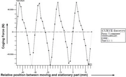
C) windings is taken as a reference model. Figure-5 shows the analysis-result of this model. The maximal cogging force is reached in 50 N. The cogging force shows that it is a periodic signals with a period is similar with the slot width of moving part.
[image:3.612.78.292.167.298.2]
Figure-5. Cogging Force of common model.
The rough analytic expression can be shown by investigation of the storage magnetic variation. It can lead to the electromagnetic force between tooth in moving part and tooth in stationary part. This force in this motor called as cogging force. The position-varying cogging force from ith tooth, becomes a periodic function of the period
m
and the electromagnetic force is expressed as follows: [image:3.612.78.293.417.532.2](1)
Figure-6. Part of common Model.
According to figure 6, the second and third slots are positioned at
sand2
s (slot pitch of stationary core) apart from the first slot, respectively. The stored magnetic energy variation in the air gap caused the position varying cogging forces that can be written as:(2)
By using a Fourier transformation, the equation 2 can be transformed into a function with the frequency as argument. By applying a Fourier expansion which it can be expressed as follows:
(3)
where are
0
o,240
o,and120
oin electrical angle, respectively. The cogging force of the DSLIM having an 8-ladder-bar 12-slot moving-core structure is obtained as follows:(4)
From equations of (4), the kth harmonic component of the cogging force of the 8-ladder-bars 12-slot core of DSLIM is summarized as
(5)
(6)
It can be seen from (6) that the cogging force of a 8-ladder-bars 12-slot moving core of DSLIM has only the triple (with integer
n
) order harmonic components while the other components cancel each other.DESIGN AND METHODOLOGY
The Design concept of the Double-Sided Linear Induction Motors (DSLIM) with ladder secondary has been developed in which employ a similar procedure as the design of any other electrical machines. It describes a problem of synthesis. The DSLIM design process consist of 4 important things: making appropriate choice the pole number and the slot number and then specify the specification design; designing the main dimensions of DSLIM and winding parameters.
The choice of pole number and slot number in stationary part involves a compromise between cogging force and magnitude of useful thrust. The harmonic content of the movable part mmf wave can be reduced by an appropriate choice of the moving slot number and coil pitch.
The three-phase signal AC is provided into the moving part winding in which are a double winding with a half-filled ends slots. The stationary part design consist of comparison of cogging performance for ladder with rectangular and trapezoid bars. The parameter design in stationary part is the width of aluminum ladder bars and thickness of the stationary iron.
The verification of the design results involves FEM simulation and experimental verification. The FEM simulation employ the cedrat 2D FLUX software. That consist evaluating the static performance and are compared with a conventional machine. For Experimental verification, the geometrical design parameters are manufactured and then connected to controller device for obtaining constant linear velocity and measurement of cogging forces.
The proposed DSLIM -Model
model, non-magnetic material bars are formed in a trapezoidal shape. The one of parameter that has impact to the magnitude of the cogging forces is the ratio between ladder-bar width to the magnetic stationary core width. And the second parameter is the ladder bar shape.
Figure-7. A Proposed trapezoid-bars of DSLIM.
The trapezoid ladder-bar model can lead to the decreasing of the magnitude of cogging forces. The useful forces remains unchanged. The optimization process involves the variation of the short sides of trapezoidal ladder-bar, the variation of tooth width of the trapezoidal ladder-bar in range between 4 – 15 mm by steps in 1 mm length. The variation of short sides shows that the short side of 3 mm, the motor has minimum cogging forces. A following paragraph show the results of the variation of tooth width of stationary part.
The DSLIM suggested in this paper having 9 Slots on moving part and cover 10 stationary slots. For a quantitative comparison of the cogging and thrust forces with those of a common single-side LIM , the suggested DSLIM is designed so that the overall armature length and the three-phase current of the motor are similar with those of the common model.
At standstill, the cogging forces in induction machines can be explained as the explanation of the tangential force in moving part of LIM. By using 1st
Maxwell equation for flux distribution in the air gap. Based on 2-D picture shown in the Figure-7 that the relationship between flux densities in the left of coil and the right of coil:
(7)
If the equation 7 is related to the 1st Maxwell equation:
[image:4.612.88.284.167.301.2](8)
Figure-8. Diagram of Flux densities in between Coils.
Where
V
f is magnetic potential in moving part,then according to voltage Maxwell electromagnetic, the cogging force acting in the slot of moving part:
(9)
Or
(10)
[image:4.612.318.538.294.371.2]The equation 40 shows that if there is no moving slot in between stationary slot, the flux densities in the air gap will be zero, and the tangential force is also zero. The distribution function (eq. 8) is shown by Figure-7.
Figure-9. f(x) Above stationary Part.
Totally the cogging force can be obtained by add up the cogging force for one slot pitch of stationary part. Figure 10 shows the model consist of only three slot pitch, by this model that totally tangential forces is positive, because in the first slot pitch it is zero and the both other slot pitch are positive. Mathematically, the resultant tangential forces per unit length at a certain instant of time, summed up over all of the moving part slots, has amplitude:
[image:4.612.347.510.427.556.2]The summation of cogging forces will repeat periodically, therefore if
d
idenotes the greatest commondivisor of
Z
1 (the number of moving part slots) and2
Z
(the number of stationary part slots), hence it follows:(12)
Figure-10. A Plot of some function f(x).
Table-1. Cogging Force and the number of slots.
slot trap. Model Z1 Z2 di
(mm) (cogging -N)
4 12 18 38 2
5 15.89 18 34 2
6 2.18 18 31 1
7 8.54 18 28 2
8 10.15 18 26 2
9 5.16 18 25 1
10 12.57 18 22 2
11 12.3 18 20 2
12 8.19 18 20 2
13 12.48 18 20 2
14 23.91 18 18 18
15 41.69 18 18 18
Z1 = the number of moving part slots Z2- the number of stationary part slots
According the equation 12, because of the equation in the bracket is always between -1 to +1, so the tangential forces depend therefore on the divisor value. If in this model the up-direction is assumed as positive tangential forces, the tooth number 1 in the top of model will be attracted in the plus direction. Table-1 shows the
relationship between cogging force and ratio number slot in moving and stationary part.
The thrust equation
The useful thrust equation can be derived using the Flux-path loop shown by Figure-11. The secondary part of model is called in this paper as a stationary part is represented by a channel
z
-axis. In the x-axis is a magnetic short circuit. Several assumptions are made at this point in order to complete the modelling.Figure-11. Schematic of magnetic circuit of DSLIM.
The teeth and slots of moving part are assumed as small thin layer (unslotted layer) into a single entity. The results of this assumption is that the moving part effects on the flux distribution can be represented by linear differential equation. The permeability of the iron is infinitive and eddy current effects are neglected. In the case of sinusoidal moving excitation, a sinusoidal distributed winding is assumed. The addition of both current densities in a loop shown in Figure-2 can be written in the equation:
(13)
It is assumed that reluctance in the stationary and moving iron is zero, so the equation 13 can be simplified into:
(14)
Where
B
gis the magnetic flux density in the airgap,
J
1sum of the primary currents of the two primarywindings,
J
2the secondary current (ladder bars instationary part) and
g
ethe equivalent air gap length. Based on the induction law, the electromotive force induced in the stationary part and speed of moving applied to a narrow rectangular loop on the surface of the stationary part conductive sheet is:(15)
(16)
The relationship between the stationary sheet surface resistivity and the induced electromotive force can be described in the Ohm’s law:
(17)
Where
sis the surface resistivity and is given by:(18)
Where
is volume resistivity andD
is the thickness of the secondary sheet. A combination between equations 16, 17 and 18, the magnetic flux density in the air gap can be obtained in:(19)
The air gap flux density is of the form :
(20)
Where
B
g(
x
)
a function of x only and current density inmoving part is can be written in form:
(21)
If the equation 20 and 21 are substituted into the equation 19, the air gap flux density can be written in double differential equation:
(22)
The complete solution of equation 19 is:
(23)
Where A is the steady state solution to the conventional machine,
C
1 andC
2 are constants, while1
and
2are roots of the auxiliary. This paper concern only for slow speed application, so at standstillv
s
0
, so that:(24)
And
(25)
With:
(26)
Where
p
,
0,f
,
m,g
are number of pole pairs, magnetic permeability of free space, frequency input power resistivity surface of winding, and air gap length (mechanical clearance). And at standstill, the thrust per unit area of pole face F per unit the linear induction motor is given by:(27)
Flow chart
The design procedure are compose of three specific levels. At the first level, the simulation of conventional model, and investigation of slot-width ratio variation on moving and stationary part. Then the cogging force magnitude is evaluated. Based on the investigation results, design of geometric parameters of DSLIM is conducted. The last level is FEM and experimental Verification. The velocity synchronous and current flowing in the coil are given and rated thrust is based on the design specification of three phases reference motor. The design procedure are shown by flow chart in Figure-12.
The DSLIM design process composed of three sections: moving part design and stationary part design and investigation of ladder-bar variation for obtaining less cogging force and not decreasing the useful thrust significantly. The iteration process using FEM is conducted with considering of the magnitude of cogging force.
Moving part parameters design
This section describes the calculating of geometric moving part parameters of DSLIM. Because the DSLIM consist of principally two sides that have symmetry dimensions each other. Therefore design concept would be developed only in one side. The design procedure are referred by common design of main dimension calculations and electrical dimension. The number of slot and winding system will be given as the first step of design.
The first important parameter in designing linear induction motor is pole pitch. The pole pitch is defined as the distance between slots where some three phase windings for one pole are connected. Due to significant influence of pole pitch to the synchronous velocity of such as linear induction motor, thus pole pitch could be calculated by using equation that describe relationship between synchronous velocity and pole pitch.
Referred to relationship between input frequency and synchronous speed and pole pitch, pole pitch can obtain in value:
(28)
number full filled slot (
Z
1) . The winding system in this design are given as double winding with 3 slots are half filled. Slot pitch can be calculated using the equation (see Figure-5)(29)
Figure-12. Flow Chart of Design.
The pole number is given that of as 2, so slot pitch can be obtained by:
(30)
For improving the distribution of magnetic flux density and reduce the resistance and reactance, this linear induction motor use chorded winding system. Based on the construction of chorded winding system, there is parameter called coil pitch parameter. It can be determined based on the slot pitch. Because was given the number of slot in which consist only half filled coil, so the coil pitch should be:
(31)
Totally, the length of primary layer can be obtained with addition of multiplication of number pole with pole pitch and coil pitch and end distance. The end width of primary in this design will be defined as that of 10 mm. Thus the length of primary layer is:
(32)
The rated thrust of small and large linear induction motor depend on the area of primary layer. According the previous designer, that for small linear induction motor for rated thrust which have thrust bigger than 100 N. Based on the thrust equation shown by equation 27, the ratio between rated thrust and the area of primary layer approximately is:
(33)
Then we can calculate area of primary layer:
(34)
The area of moving part is multiplication between depth and width of moving part. If the primary width has already calculated, so the primary depth may be obtained easily.
(35)
The three phases AC current signal flowing in primary coil generated the travelling magnetic flux in air-gap. This magnetic flux influence or induced voltage signal into the secondary layer of LIM. Typically, the induced voltage in secondary layer is approximated about a half of the rms value of input voltage signal.
(36)
According to curve efficiency for the single-sided linear induction motor for small LIM [2] can be assumed as
cos
0
.
115
and maximum input current in coil of moving part layer can be predicted:(37)
Based on the output coefficient line current density and the output coefficient, with assuming that
T
B
z
0
.
4
, approximately line current density can be calculated by using this methods)(38)
The thickness of aluminum can be defined as
FEM verification
The design results are verified by FEM-software. Based on the post processing of the numerical results which it is associated with these designed model, the main characteristics of the DSLIM are evaluated. The digital numerical calculation which the solution of model are accounted step by step in discrete form of signals.
The design geometric model should be created. The creation of the geometric model is divided into various steps: create half moving part slot and create half stationary part slot with regions, mesh and transformations of symmetry; create full moving part and stationary part; create core of stationary part and mesh the whole geometry.
Figure-13 shows the model of designed DSLIM. The model consist two part: moving and stationary part. The moving parts are placed in between the stationary part. The stationary part compose of the ladder bars. The number of moving slot is 9 slots, and in the stationary is 12 slots. The model have two the air gap. The air gap separates the moving to the stationary part.
This solution of models are supported by the Cedrat FLUX2D software packages. The Flux densities distribution on whole model showed by Figure-15. The colored picture on Figure-14 represents that flux densities on whole model are under 0.9 Tesla. However it shows that in edge of iron bar near to trapezoid bar have a big flux density in about 1.5 Tesla. This is one factor of disadvantage of trapezoidal model.
Figure-15 shows the comparison between rectangular-bar model and trapezoid-bar model. It describes that the trapezoid model can generate the useful thrust bigger than rectangular model and. The cogging forces can be reduced under 10% for trapezoid-bars.
Experimental verification
Design results of DSLIM is manufactured at the Workshop of University of Wollongong (UOW) Australia. According the last design results of the DSLIM motor, the model with trapezoidal ladder-bar is decided to be manufactured. For simplicity of manufacturing process, the stationary ladder-bar are in rectangular and slots in moving part in trapezoidal shape. The tooth and slot width in moving and in stationary are unchanged. The number and cross section of coils and the structure of winding are similar with the previous design results. Figure-18 shows the manufactured moving part of DSLIM model.
The experimental test-bed is connected to PC-host, PC-target and Baldor controller. Figure-5.8 shows the connections between PC-Host, PC-Target, Baldor controller and LSLIM in this experiment. They consist of 7 components: PC-target, PC-Host, DAC interface card, Inc. Encoder interface card, Baldor controller, Linear encoder sensor and rotary induction motor.
Figure-13. DSLIM-Model in Cedrat FLUX Software.
Figure-14. Flux densities distribution on Model.
Figure-15. Force-speed characteristic of trapezoid ladder-Bar.
Figure-19 shows the cogging forces which is obtained from this measurement of DSLIM-Motor. The maximum cogging force of motor is about 4.5 N. Therefore the percent ratio between the cogging force and the useful thrust is 4.0 %. Figure-19 shows the frequency spectrum of the cogging force. Based on this spectrum, it indicates that the fundamental frequency of signal is 0.2 Hz. This Figure shows that a cogging force has period is about 20 mm long which is equal to the slot pitch of motor.
Figure-16. Comparison Thrust and Cogging for trapezoid
and Rectangular Bars.
Figure-17. Physical Moving Part of DSLIM.
Figure-18. Cogging Force Measurement.
CONCLUSIONS
A double-sided linear induction motor design with minimum cogging forces has been developed for a slow range linear movement speeds applications. The design results shows that with ladder trapezoid-shape bar, the magnitude of cogging force in DSLIM motor can be reduced until 4% compared with the useful thrust. According the experimental verification the maximum cogging force in this motor is 4 N for maximum thrust about 400 N thrust. Compared with the conventional model, its cogging force is 50 N for 350 N maximum thrust. The decreasing of the cogging force do not influence the maximum useful thrust significantly.
Figure-19. Frequency Spectrum of Cogging Force Signal.
REFERENCES
[1] Alger P. L. 1970. Induction Machines, Gordon and Breach Science Publishers, New York.
[2] Brandenburg G., Brueckl S., Dormann J., Henzi J., Smidtc C. 2000. Comparative Investigation of Rotary and Linear Motor feed Drive Systems for High Precision Machine Tools. IEEE AMC2000-Nagoya.
[3] B. T. Ooi. 1973. A Generalized Machine Theory of Linear Induction Motor, Presentation paper on PES Winter Meeting, New York.
[4] Gieras J. F. 1994, Linear Induction Drives, Clarendon Press, Oxford.
[5] Lee B.J., Koo D H and Cho Y H 2008, Investigation of Secondary Conductor type of linear Induction Motor Using the Finite Element Method, Proceeding of IEEE the 2008 International Conference on Electrical Machines.
[7] Nonaka S. and T. Higuchi. 1987. Elements of Linear Induction Motor Design, IEEE Transactions on Magnetic, Vol. MAG-23, No. 5.
[8] Rusli M., Moscrop J., Cook C. and Platt D. 2011. An Analytical Method for Predicting Cogging Forces in Linear Induction Motors, Proceeding of 8th LDIA
conference, Netherland, 3-6 july 2011.