Application of APC Technique in a Unique Standalone
Hybrid Generation Systems
Mr.M.Vimalraj
1, Mr.R.Mageshwaran
2, Mr.B.Karthikeyan
3&,Ms.M.Tamilarasi
4 1,2,3PG Student,Kingston Engineering College,Vellore,Tamil Nadu,India.4
Assistant Professor, Kingston Engineering College,Vellore,Tamil Nadu,India.
Abstract- This paper proposes a unique standalone hybrid power
generation system, applying advanced power control
techniques(APC), fed by four power sources: wind power, solar power, storage battery, and fuel cell, and which is not connected to a commercial power system One of the primary needs for socio-economic development in any nation in the world is the provision of reliable electricity supply systems. This work is a development of an indigenous technology hybrid Solar –Wind and fuel cell Power system that harnesses the renewable energies in Solar- Wind and fuel cell to generate electricity. Here, electric DC energies produced from photovoltaic and wind turbine systems are transported to a DC disconnect energy Mix controller. The controller is bidirectional connected to a DC-AC float charging-inverter system that provides charging current to a heavy duty storage bank of Battery and at the same time produces inverted AC power to AC loads. This paper focuses on the modeling and simulation of solar – photovoltaic, wind, fuel
cell and battery hybrid energy systems using
MATLAB/simulink.
Index Terms- low cost, standalone hybrid power generation
system, storage battery, more efficiency,Socio –Economic
development.
I. INTRODUCTION
Hybrid renewable energy system combines two or more energy sources, usually solar and wind power. The main advantage of hybrid system is the enhancement of reliability of the hybrid generation system used. Also, the battery size can be reduced as the Solar and Wind energy sources are complementary in nature .The surge for suitable alternative energy sources is growing more intense than ever in order to reduce the heavy dependence on fossil fuels. Fuel cells are another rapidly developing generation technology. Fuel cells have high efficiency, low carbon emissions, high reliability due to the limited number of moving parts and longer life than batteries.
The major components include P.V modules, battery and inverter. The most efficient way to determine the capacities of these components is to estimate the load to be supplied. The size of the battery bank required will depend on the storage required, the maximum discharge rate, and the minimum temperature at which the batteries will be used. When designing a solar power system, all of these factors are to be taken into consideration when battery size is to be chosen. Lead-acid batteries are the most common in P.V systems because their initial cost is lower
and also they are readily available nearly everywhere in the world. Deep cycle batteries are designed to be repeatedly discharged as much as 80 percent of their capacity and so they are a good choice for power systems
1.1 IMPORTANCE OF RENEWABLE ENERGY The
global search and the rise in the cost of conventional fossil fuel is making supply-demand of electricity product almost impossible especially in some remote areas. Generators which are often used as an alternative to conventional power supply systems are known to be run only during certain hours of the day, and the cost of fueling them is increasingly becoming difficult if they are to be used for commercial purposes.
Fig.1. Standalone hybrid wind –solar and fuel cell power generation system.
II. SOLARENERGY
Solar energy is energy from the Sun. It is renewable, inexhaustible and environmental pollution free. Nigeria, like most other countries is blessed with large amount of sunshine all the year with an average solar power. Solar charged battery systems provide power supply for complete 24hours a day irrespective of bad weather. Moreso, power failures or power fluctuations due to service part of repair as the case may be is non-existent.
2.1 SOLAR-GENERATED ELECTRICITY –
PHOTOVOLTAIC
be captured in the form of a D.C current. The generated electricity can be used to power a load or can be stored in a battery.
Photovoltaic system is classified into two major types: the off-grid (stand alone) systems and inter-tied system. The off-grid (stand alone) system are mostly used where there is no utility grid service. It is very economical in providing electricity at remote locations especially rural banking, hospital and ICT in rural environments.
PV systems generally can be much cheaper than installing power lines and step-down transformers especially to remote areas.
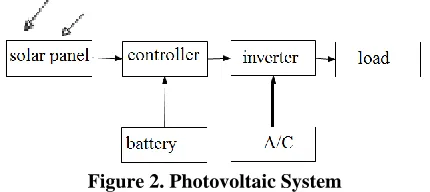
[image:2.612.60.275.277.373.2]Solar modules produce electricity devoid of pollution, without odour, combustion, noise and vibration. Hence, unwanted nuisance is completely eliminated. Also, unlike the other power supply systems which require professional training for installation expertise, there are no moving parts or special repairs that require such expertise.
Figure 2. Photovoltaic System
2.2 CHARGING CONTROLLER
The need for Charging Controllers is very important so that overcharging of the batteries can be prevented and controlled. The controllers to be used required the following features:
1. Prevent feedback from the batteries to PV modules.
2. It should have also a connector for DC loads.
3. It should have a work mode indicator.
2.3 BOOST CONVERTER
The boost dc-dc converter will boost the volts when the below 16v from the solar. Several different boost converter designs have been developed in the past. In order to achieve the results specified for this project, the output voltage of the converter needs to be higher than the input voltage. This type of converter operates in the flyback-mode. When the transistor is conducting, current is being drawn through the inductor. At this time energy is being stored in the inductor. When the transistor stops conducting the inductor voltage flies back or reverses because the current through the inductor cannot change instantaneously. The voltage across the inductor increases to a value that is higher than the combined voltage across the diode and the output capacitor. As soon as this value is reached, the diode starts conducting and the voltage that appears across the output capacitor, is higher than the input voltage.
2.4 SOLAR INVERTERS
The Solar inverters are electrical device meant to perform the operation of converting D.C from array or battery to single or three phase A.C signals. For P.V Solar Systems, the inverters are incorporated with some inbuilt protective devices. These include:
1. Automatic switch off if the array output is too high or too
low.
2. Automatic re-start.
3. Protecting scheme to take care of short circuit and
overloading. Generally the inverter to be used that would produce the quality output must have the following features .
4. Overload protections.
5. Miniature Circuit Breaker Trip Indicator(MCB).
6. Low - battery protection.
7. Constant and trickle charging system.
8. Load status indicator.
III. WINDPOWER
Wind Power is energy extracted from the wind, passing through a machine known as the windmill. Electrical energy can be generated from the wind energy. This is done by using the energy from wind to run a windmill, which in turn drives a generator to produce electricity. The windmill in this case is usually called a wind turbine. This turbine transforms the wind energy to mechanical energy, which in a generator is converted to electrical power. An integration of wind generator, wind turbine, aero generators is known as a wind energy conversion system (WECS).
3.1 WIND TURBINE
A wind turbine is a machine for converting the kinetic energy in wind into mechanical energy. Wind turbines can be separated into two basic types based on the axis about which the turbine rotates.
3.2 WIND POWER MODELING
The block diagram in figure 4 shows the conversion process of wind energy to electrical energy.
Figure 3: Energy conversions from Wind to Electrical
The generator is based on the park transformation and the rectifier consists of 6 rectifiers which are placed in bridge. The inverter consists of a MOS inverter and a current controller which generates the control signals for the mosfets. The current controller measures the output currents and compares it with a reference current and changes the control signals of the mosfets in accordance to the difference between the real and the reference currents. Three controlled voltage source blocks are needed because the power system block set contains no sinusoidal voltage sources.
annual/monthly mean wind speed of the site. The Wiebull distribution function has been proposed as a more generally accepted model for this purpose. The two-parameter Wiebull distribution function is expressed mathematically in equation 3 as The kinetic energy of the wind (air mass m wind speed v) is given by the following equation:
(1)
With:
(With S: Covered surface of the turbine and p: the air density)
The wind power��has the following expressions:
(2)
The mechanical power that the turbine extracts from the wind is inferior to. This is due to the fact that the wind speed after the turbine isn’t zero (the air needs to be carried off after the turbine). So, the power coefficient of the turbine can be defined by:
(3) The recuperated power is given by:
(4) With R: radius of the rotor
Depends of the tip speed ratio of the wind turbine and angle of the blades
(5) Is the rotation speed of the rotor
A maximum for this function can be found and this maximum is known as the limit of Betz:
(6)
The wind turbine torque on the shaft can be calculated from the power:
(7) 3.3 GENERATOR MODEL
The PMSG has been considered as a system which makes possible to produce electricity from the mechanical energy obtained from the wind. The dynamic model of the PMSG is derived from the two-phase synchronous reference frame, which the q-axis is 90o ahead of the d-axis with respect to the direction of rotation .The synchronization between the d-q rotating reference frame and the three phase frame is maintained by utilizing a phase locked loop.
The PMSG can be model led by using the simulation tool MATLAB Simulink. The equations used to model the PMSG are:
(8)
3.4 BUCK CONVERTER
The buck dc-dc converter control the power when the voltage above 16v from the wind. A power electronic converter uses semiconductor devices to transform power from one form (DC or AC) into another form (DC or AC). It accomplishes this by causing the circuit topology to change by virtue of turning ON and OFF the semiconductor devices. A buck converter is a specific type of dc-dc power electronic converter whose goal is to efficiently step downDC voltage to a lower level with minimal ripple. Practical applications are illustrated in a buck chopper might interface between the varying output voltage of a storage battery and a sensitive piece of electronics such as a microprocessor. Typically the buck converter employs feedback to regulate the output voltage in the presence of load changes.
3.5 FUEL CELL
A fuel cell is a device that converts the chemical energy from a fuel into electricity through a chemical reaction with oxygen or
another oxidizing agent.Hydrogen is the most common fuel, but
hydrocarbons such as natural gas and alcohols like methanol are
sometimes used. Fuel cells are different from batteries in that
they require a constant source of fuel and oxygen to run, but they can produce electricity continually for as long as these inputs are supplied.
Welsh Physicist William Grove developed the first crude fuel
cells in 1839. The first commercial use of fuel cells was in
NASA space programs to generate power for probes, satellites
and space capsules. Since then, fuel cells have been used in many other applications. Fuel cells are used for primary and backup power for commercial, industrial and residential buildings and in
remote or inaccessible areas. They are used to power fuel cell
vehicles, including automobiles, buses, forklifts, airplanes, boats, motorcycles and submarines.
There are many types of fuel cells, but they all consist of an
anode (negative side), a cathode (positive side) and an electrolyte
that allows charges to move between the two sides of the fuel cell. Electrons are drawn from the anode to the cathode through
an external circuit, producing direct current electricity. As the
main difference among fuel cell types is the electrolyte, fuel cells
are classified by the type of electrolyte they use. Fuel cells come
in a variety of sizes. Individual fuel cells produce relatively small electrical potentials, about 0.7 volts, so cells are "stacked", or placed in series, to increase the voltage and meet an application's requirements. In addition to electricity, fuel cells produce water, heat and, depending on the fuel source, very small amounts of
3.6 PROTON EXCHANGE MEMBRANE FUEL CELL The proton exchange membrane fuel cell (PEMFC) uses a water-based, acidic polymer membrane as its electrolyte, with platinum-based electrodes. PEMFC cells operate at relatively low temperatures (below 100 degrees Celsius) and can tailor electrical output to meet dynamic power requirements. PEMFC cells are currently the leading technology for light duty vehicles and materials handling vehicles, and to a lesser extent for stationary and other applications. The PEMFC fuel cell is also sometimes called a polymer electrolyte membrane fuel cell (also PEMFC).
Hydrogen fuel is processed at the anode where electrons are separated from protons on the surface of a platinum-based catalyst. The protons pass through the membrane to the cathode side of the cell while the electrons travel in an external circuit, generating the electrical output of the cell. On the cathode side, another precious metal electrode combines the protons and electrons with oxygen to produce water, which is expelled as the only waste product; oxygen can be provided in a purified form, or extracted at the electrode directly from the air.
A variant of the PEMFC which operates at elevated temperatures is known as the high temperature PEMFC (HT PEMFC). By changing the electrolyte from being water-based to a mineral acid-based system, HT PEMFCs can operate up to 200 degrees Celsius. This overcomes some of the current limitations with regard to fuel purity with HT PEMFCs able to process reformate containing small quantities of Carbon Monoxide (CO).
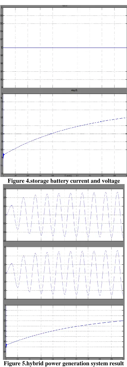
3.7 STORAGE BATTERY
[image:4.612.337.551.49.666.2]Traditionally, battery banks have been a technology only used primarily in hybrid power systems that are not connected to the electrical grid. The reason for this is fairly obvious: Off-grid homes need reliable power even at night, and hybrid’s are generally the most cost-effective way to generate it, With grid-connected hybrid systems (which are these days by far the more numerous type), batteries are not necessary because the electricity grid functions as a kind of bottomless battery bank.
Figure 4.storage battery current and voltage
Figure 5.hybrid power generation system result
IV. CONCLUSION
There is the need for the provision of an alternative sustainable electric power supply system to provide electricity to rural and the unreached communities.A complete model simulating the proposed hybrid generation system including the wind, solar, fuel cell and storage battery system is done using Matlab/Simulink. The simulation results showed satisfactory performance of the hybrid system.PIC microcontroller based for solar module has been realized in hardware and unit sizing of the hybrid system is also presented. The future work will be to design the proposed hybrid system and implement in hardware. Also, the system has to be extended to higher ratings and solve for the synchronization issues.
REFERENCES
[1] Xin Wang Yuvarajan, S. Lingling Fan., “MPPT control for a PMSG-based grid-tied wind generation system”, IEEE Transactions on Energy Conversion, 2010
[2] Yuvarajan, S. Kaderbhai, M. ,“Hybrid Renewable Energy System with Wind Turbine and PV Panels”, Green Technologies Conference, 2010 IEEE , pg:1 – 4
[3] Weidong Xiao, , Nathan Ozog, and William G. Dunford “Topology Study of Photovoltaic Interface for Maximum Power Point Tracking”, IEEE Trans. Ind. Electronics, vol. 54, no. 3,June 2007.
[4] Trishan Esram, and Patrick L. Chapman, “Comparison of Photovoltaic Array Maximum Power Point Tracking Techniques” IEEE Trans. Energy Conversion, vol. 22, no. 2, June 2007
[5] Eftichios Koutroulis and Kostas Kalaitzakis , “Design of a Maximum Power Tracking System for Wind-Energy-Conversion Applications”, IEEE Trans. Ind. Electronics, Vol. 53, NO. 2, April 2006 pg no: 486-494.
[6] Wolf Vielstich,Arnold Lamm, Hubert A. Gasteiger “Handbook of Fuel Cells: Fundamentals,Technology, Applications”, Wiley, 2003
[7] T. Kerekes, R. Teodorescu, and U. Borup, “Transformerless photovoltaic inverters connected to the grid,” in Proc. IEEE APEC Conf., 2007, 733– 1737.
[8] O. Lopez, R. Teodorescu, F. Freijedo, and J. Doval-Gandoy, “Eliminating ground current in atransformerless photovoltaic applictation,” in Proc. IEEE PES Conf., 2007, pp. 1–5.
[9] R. Gonzalez, E. Gubia, J. Lopez, and L. Marroyo, “Transformerless single-phase multilevel-based photovoltaic inverter,” IEEE Trans. Ind. Electron., vol. 55, no. 7, pp. 2694–2702, Jul. 2008.
[10] R. Gonzalez, E. Gubia, J. Lopez, and L. Marroyo, “Transformerless single-phase multilevel-based photovoltaic inverter,” IEEE Trans. Ind. Electron., vol. 55, no. 7, pp. 2694–2702, Jul. 2008
[11] J. A. Baroudi, V. D. Dinavahi, and A. M view of power converter topologies for wind generators,”Renewable Energy 32, Science Direct, pp. 229 January, 2007.
[12] Z. Chen and E. Spooner, “Current source thyristor in-verter and its active compensation system,” Proceedings of IEE Generation, transmission and distribution vol.150 ,july 2003
AUTHORS
First Author – Mr.M.Vimalraj received
B.E(Electrical & Electronics Engineering) from Ganadipathy Tulsi’s Jain Engineering College, Vellore (TN), India in 2011 and he is currently a PG student in Power Systems Engg from Kingston Engg College, Vellore (TN), India. He has been working in teaching field. Areas of interest are include Renewable Energy Resources, Electrical machines, FACTS, Soft Computing.
Second Author – Mr.R.Mageshwaranreceived
B.E(Electrical & Electronics Engineering) from SKP Engg College, T.V.Malai (TN), India in 2013 and he is currently a PG student in Power Systems Engg from Kingston Engg College, Vellore (TN), India. His Areas of interest are include FACTS Renewable Energy Resources, Electrical machines.
Third Author – Mr.B.Karthikeyan received
B.E(Electrical & Electronics Engineering) from SA Engg College, Chennai (TN), India in 2013 and he is currently a PG student in Power Systems Engg from Kingston Engg College, Vellore (TN), India. His Areas of interest are include Renewable Energy Resources, Electrical machines.
Fourth Author – Ms.M.Tamilarasi obtained her B.E(Electrical