Bufferfloat Mitigation for Real-time Video Streaming
using Adaptive Controlled Delay Mechanism
Matilda.S
Professor, Department of Information Technology IFET College of Engineering
Villupuram, India
B.Palaniappan
Professor, Department of Computer Science Annamalai University
Chidambaram, India
Thambidurai.P
Professor,
Perunthalaivar Kamarajar Institute of Engineering & Technology, Karikal, India
ABSTRACT
Bufferbloat is an abnormal phenomenon in current Internet ex-perience where large buffers cause high end-to-end latency and jitter, as well as throughput degradation. The universally applied thumb rule is used to allocate buffers at the nodes, based on the assumption that large size buffers reduce packet loss. Window scaling mechanism of TCP tends to fill up these buffers caus-ing latency in the network. CoDel has been designed to over-come bufferbloat. The drawback in CoDel is that, the uniform target values does not support real-time video streaming. Adap-tive CoDel proposed in this paper tends to mitigate bufferbloat and improve the QoS parameters of real-time video stream.
General Terms:
Communication Networks, Adaptive Control
Keywords:
Bufferbloat, CoDel, Real-time Video, Adaptive CoDel
1. INTRODUCTION
The rapid growth of the Internet and the proliferation of new applications pose a serious challenge in network performance management and monitoring. TCP has a number of performance issues in this relatively new environment, including extremely long delays and sub-optimal throughput in certain scenarios [1]. Bufferbloat is an abnormal phenomenon in current Internet ex-perience where large buffers cause high end-to-end latency and jitter, as well as throughput degradation [2]. Bufferbloat in cel-lular networks nullifies loss-based congestion control and allows excessive growth of the TCP congestion window, resulting in ex-tremely long delays and throughput degradation. Surprisingly, the performance of TCP over cellular networks has been under-explored due to the closed nature of cellular networks [1], though 90% of the total traffic is handled by TCP [3]. Long delays and throughput degradation observed in previous studies [4, 5, 6] makes the existing Internet setup unsuitable for streaming real-time video. To support such applications, end-to-end control that adapts to the changing dynamics of the network has to be de-ployed. This ensures delivery of video of acceptable quality to users, in terms of packet loss, end-to-end delay and jitter.
Im-proper buffer sizing has been identified as one of the most critical reasons behind the performance degradation [1].
2. BUFFER MODELS IN THE INTERNET
The purpose of buffers is to absorb bursts of traffic, which of-ten occur in a network. TCP has been designed to fill up all the buffers on the path. High speed variants of TCP were originally designed for efficient increasing the throughput capacity in large Bandwidth Delay Product (BDP)networks. But in bufferbloated cellular networks, they only make the problem worse by constant overshooting. Therefore, the bufferbloat problem adds a new di-mension in the design of a new efficient TCP, especially for cel-lular networks. In bufferbloated celcel-lular networks, the motive to attain nearly zero packet loss rate combined with the aggressive nature of high speed TCP variants result in severe congestion window overshooting [1]. An insight into the existing buffer de-sign would throw light on the abnormal behavior of the Internet.
2.1 Universally Applied Rule of the Thumb
This was derived based on Villamizar and Songs experiments and is applicable for a single long-lived TCP flow going through the bottleneck link. The rule is defined by the following expres-sion
Buf f erSize=RT T×C (1) where RTT is the Roundtrip Time and C is the Channel capac-ity of the bottle-neck link [7]. This BDP value is applied in de-sign of networks even till date. It holds good if the links are syn-chronized and supports a single flow. A typical backbone node supports more than 20,000 flows and the arrival pattern follows Poisson distribution.
2.2 Small Buffer Model
Appenzeller et al. proposed this model by applying Central Limit theorem to narrow down the width of the Gaussian fluctuation. This reduces the buffer size by a factor√N when there are N long-lived TCP flows sharing the link
Buf f erSize=RT T√ ×C
N (2)
2.3 Tiny Buffer Model
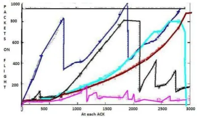
[image:2.595.70.264.402.518.2]This model suggests a buffer size of just 20 -50 packets. This rule assumes that throughput and link utilization could be sacri-ficed by 10 -15% This was basically designed for optical routers, where link is not a bottleneck but buffer is the bottle neck [9]. All the generic models discussed above have been designed con-sidering only data traffic which was dominant in the networks of second generation. 3G and 4G networks add some interest-ing challenges of its own, with its quickly varyinterest-ing link speeds and complexities added by packet aggregation. Large buffers in wireless networks are essential for the link layer in which packets experiencing channel errors are buffered. However, since the side-effects to TCP brought by over-buffering has not been well understood, the problem still prevails in todays cellular net-works. Haiqing Jiang and team from North Carolina State Uni-versity performed real-world tests to study the presence and ef-fects of bufferbloat in networks. The results revealed abnormal behavior of TCP in bufferbloated cellular networks, leading to a number of performance issues including long delays and sub-optimal throughput. In applications where fat TCP was observed, the buffer size was set using the BDP value [2]. In flat TCP, the parametertcp rmem max plays a crucial role in suppress-ing packet loss and obtainsuppress-ing a flattened throughput. In small BDP networks, fat\flat TCP develop unnecessarily long end-to-end latency due to excessive queuing. Flat TCP will suffer from significant throughput degradation in large BDP links. Figure 1 shows the presence of very large buffers in real-time networks in a study conducted by Kathleen Nichols and Van Jacobson
Fig. 1. Result of study by Kathleen Nichols and Van Jacobson depicitng Bufferbloat in the Internet.
3. EXISTING SOLUTIONS TO MITIGATE BUFFERBLOAT
Bufferbloat problem is defined as buffering of packets causing high latency and jitter, which ultimately leads to reduction in network throughput. With memory cheap, every manufacturer assumes that the best thing to do is make buffers as large as pos-sible. Furthermore, the misguided desire to avoid packet loss has led to larger buffers being deployed in the hosts, routers, and switches. To wave a wand and eliminate bufferbloat overnight is not possible as it has been spread throughout the Internet.
3.1 Active Queue Management
The first solution offered was Active queue management (AQM), which attempts to keep the queues at the bottleneck from grow-ing too large by monitorgrow-ing the growth of the packet queue. If the queue grows beyond the permitted limit it signals the senders TCP to slow down by dropping or marking packets. Various ap-proaches have been taken to monitoring the packet queue and making the drop or mark decision. One flavor of AQM is the RED manifesto which is based on the fact that, packet loss is
not a problem in TCP but is an essential mechanism for func-tioning in the face of congestion. RED determines that the queue length is getting long, and then randomly selects packets within the queue for discard. This technique does not support streaming of real-time video. Another disadvantage is that AQM has to be configured in routers. This requires implementation of a patch in all the nodes in the Internet. In practice AQM is not widely con-figured or enabled in routers and it is completely unavailable in many devices.
3.2 Dynamic Right-Sizing (DRS)
The fundamental goal of DRS is to allocate just enough buffer so that the throughput of the TCP connection is never limited by the receive window size but only constrained by network conges-tion. DRS dynamically adjusts the receive buffer size to suit the connections demand. For each RTT, the receiver estimates the senders congestion window and then advertises a receive dow which is twice the size of the estimated congestion win-dow [10]. While flow control is preserved by DRS, most of the time, the receive window and the receive buffer size undergoes dynamic adjustments. However, this dynamic adjustment is uni-directional: DRS increases the receive window size only when it might potentially limit the congestion window growth but never decreases it. Further studies revealed that DRS , is a subopti-mal ad-hoc solution to mitigate bufferbloat. It merely mitigates bufferbloat problem only in some scenarios
3.3 Dynamic Receive Window Adjustment (DRWA)
Dynamic receive window adjustment (DRWA) algorithm tends to improve TCP performance over bufferbloated cellular net-works. The aim of DRWA is to adaptively set the receive win-dow to a proper size in different environment. DRWA is built on top of DRS. Instead of a unidirectional adjustment where the advertised window is non-decreasing, we need a bidirectional adjustment algorithm to rein TCP in the buffer-bloated cellular networks but at the same time to ensure full utilization of the link. To accomplish that, DRWA needs to keep the queue size within a proper range dynamically. According to real-world tests performed, DRWA reduces the delay by 25 to 49% in general cases and increase TCP throughput by up to 51% in some spe-cific scenarios. Since DRWA requires modification at the client side (e.g., smart phones) only and is fully compatible with exist-ing TCP protocol and is immediately deployable.
3.4 The Controlled Delay (CoDel) mechanism
reason-able values, on a CoDel-managed node. The authors have found that that a target of 5ms and an interval of 100ms work well in any setting [11]. The use of time values instead of packet or byte counts makes the algorithm function independently of the speed of the links.
3.5 Drawbacks in the existing methods
In simulation results, CoDel compares favorably to the common RED in most regards. RED requires careful tuning of parame-ters to work well, while CoDel works within a broad range of bandwidths without the need to change any settings. CoDel al-ways kicks in, when standing queues exceed five milliseconds [12]. CoDel has implementation advantages over other AQMs as it does nearly all of its work at the dequeue stage (when pack-ets are transmitted). CoDel requires adding a timestamp to each individual packet as it is received, but even if the network hard-ware can’t do this, timing information can be directly obtained from the CPU register in modern CPUs. But assuming a uniform target value of 5 ms irrespective of the incoming and outgoing bandwidth does not work well. This also does not fare well with higher number of hops and varying RTT which is typical in video streaming.
[image:3.595.330.529.148.220.2]4. ANALYSIS OF THE EXISTING INTERNET
Table 1. Extract of Netalyzr Report.
Parameter Value
No. of Hops 21
Network Latency 270 ms
TCP connection setup latency 290 ms
Packet Loss 0.5%
Network Bandwidth: Uplink 210 Kbps Network Bandwidth: Downlink 2.4 Mbps Network Buffer: Uplink 969 ms Network Buffer: Downlink 150 ms
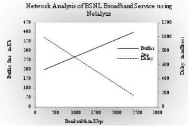
[image:3.595.331.515.343.450.2]To simulate a realistic environment, an existing BSNL broad-band connection was analysed using Netalyzr. Extract of report of BSNL Broadband Network obtained using Netalyzr is shown in table 1.
[image:3.595.93.249.369.469.2]Figure 2 shows the variation of Delay and Buffer Size with vary-ing bandwidth as predicted by Netalysr in a BSNL Broadband connection. For low values of bandwidth, the delay is very high. This confirms bufferbloat in the network. The high value of de-lay predicted by Netalyzr makes the network unsuitable for real-time applications. One day International Cricket match between
Fig. 2. Delay and Buffer Size measured in BSNL broadband Service using Netalysr
India and Pakistan on 30th December 2012 was live streamed
to observe the effect of the network on real-time video stream-ing. Figure 3 shows the data rate spread over a period of 1000 seconds while streaming the cricket match.
Fig. 3. Real-time Video Profile captured by Wireshark
Traceroute results showed 18 hops between the client and the server with Packet loss of 5%. Typically more than 5% lost pack-ets will annoy users [13]. It was observed that delay distribution has a gamma-like shape with heavy tail.The received packets were analysed using wireshark and showed an average delay of 332 ms.
Fig. 4. Packet Delay traced during live streaming of cricket match
Figure 4 shows the delay spread over a period of 1000 ms during the capture. This delay averages out to 18.4 ms across each link. Hence the target value of 5 ms set in Codel would miserable fail and reduce throughput in this network.
Fig. 5. RTT and delay components across each hop
[image:3.595.335.517.561.675.2] [image:3.595.71.263.601.729.2]5. MATHEMATICAL MODEL OF BUFFER DESIGN
The buffer sizing problem is a stochastic, non-liner problem with an integer decision vector. It is a hard combinatorial optimiza-tion problem, which is made more difficult by the fact that it is not obtainable in a closed form to interrelate diagonally opposite metrics like throughput, delay, link utilization and packet loss. General Formulation is as follows:
ExtremizeZ = {f1(¯x), f2(¯x), f3(¯x), f4(¯x),
f5(¯x), f6(¯x), f7(¯x), f8(¯x)} (3)
Where
f1(¯x) is the average throughput
f2(¯x) is the end-to-end delay
f3(¯x) is the average packet loss
f4(¯x) is the average link utilization
f5(¯x) is the buffer size in core routers
f6(¯x) is the buffer size in edge routers
f7(¯x) is the buffer size at the sender
f8(¯x) is the buffer size at the receiver
Of thesef5(¯x)tof8(¯x), are integer values which are
intercon-nected ,fixed and are to be determined. Hence other forms in which the problem can be formulated are
P1:max(θ) =f1(¯x), ifPixi≥µ
Whereθis the average throughput,xi is the buffer in devicei andµis the link capacity.
Throughput can be analysed using queuing theory where packet rate is denoted byλand throughput or departure rate is given byθ. Maximum throughput is equal to link capacity at the out-put . Hence the desired equation ismax(θ) =µ. Average link utilization is given by
AverageT hroughput
LinkCapacity ×100% (4)
In a point-to-point link or point-to-multipoint link, with only one server transmitting, maximum throughput is obtained and channel utilization of almost 100% can be achieved, except for the small interframe gap. For example in the Ethernet the maximum frame size is 1526 bytes. An interframe gap of 12 bytes is inserted after every frame. Hence maximum channel utilization is 99.22%. This implies that in a 100 Mbps link the maximum throughput which can be achieved is 99.2 Mbps inclusive of data link layer overhead. Maximum achievable throughput exclusive of data link layer overhead is 97.5Mbps. This in addition to other analog limitations, physical character-istics of the links, interference and hardware limitations reduce the overall throughput.
P2:In this form the problem is to determine how to allocate buffers in a connection with n hops which requiren+ 2buffers
min(P
ixi)s.t.θ >Θ´
whereΘ´ is the feasible or achievable throughput. A minimum buffer size is desired to reduce end-to-end delay, but this de-creases the throughput and inde-creases the packet loss. The dif-ficulty in the above optimization problem is that there is no ex-plicit expression for average throughput and average data in the queue in terms of buffer space. These values are usually obtained from steady state distribution of packets in the buffers. Thus due to lack of differential functions that are assumed in optimization problems the approach used is an heuristic one.
The optimization methods used in general to find a solution for optimal buffer size are Enumeration Method, Search methods
such as Simultaneous search methods with multiple variables and Analytical Method. Closed loop solutions for buffer design have also been studied. All these methods are capable of address-ing the combinational nature of buffer sizaddress-ing problem but cannot be applied for a larger line and hence fail to provide a global op-timum buffer size. As a result these methods cannot be applied to the Internet which spans the entire globe.
6. ADAPTIVE CONTROLLED DELAY MECHANISM (ADAPTIVE CODEL)
The fact that buffer sizing has to vary with the bandwidth sup-ported by the outgoing link is the basis of this mechanism. It does not tend to vary the size of the buffer, but varies the queu-ing delay each packet experiences in the buffer. Adaptive CoDel redefines the target and interval to suit the current network pa-rameters. These values are based on the value of RTT, which varies with each segment.
6.1 Setting-up of Initial Values
As per economical design of buffer, capacity of buffer at any time should be sufficient to hold the number of packets required for immediate consumption by the application. For example, in an application where every tenth packet is counted or if only the tenth packet has the required information, it is sufficient to de-sign a buffer with a capacity to hold 10 packets [14]. For H.264 encoded video stream this value is equal to one GoP. Hybrid Transport Layer protocol approach is used to stream the real-time video. I frames are transmitted using TCP while the less priority Band P frames are transmitted using UDP [15]. The following initial values are set:
W indowSize = 1GoP (5)
InitialDelay = 2×1GoP
BW eakestLink (6)
1 GoP is the size of the total frames constituting one GoP of the encoded video stream andBW eakestLink is the Bandwidth of the weakest link along the path. The initial delay is approxi-mated to the time taken for 1 GoP to arrive at the receiver and acknowledgement to reach the sender provided the bandwidth of the weakest link is greater than or equal to the playback speed of video.
6.2 RTT Estimation
One method of estimating RTT for calculations is to find the av-erage of all the RTTs for those segments which have been ac-knowledged. This is implemented in estimating the timeout pe-riod for the retransmission timer.
ART T(K+ 1) = 1
K+ 1
K+1
X
i=1
RT T(i) (7)
This expression can be rewritten as
ART T(K+ 1) = K
K+ 1ART T(K) + 1
K+ 1RT T(K+ 1)
(8)
of the current network environment. Greater weightage to more recent instances is likely to reflect the future behavior much bet-ter. RFC 793 suggests predicting the next value on the basis of a time series of the past values using exponential averaging. The expression for Smoothed RTT according to RFC 793 is given by equation 9.
SRT T(K+ 1) =α×SRT T(K) + (1−α)×rtt(K+ 1) (9) Where0< α <1. The advantage of using a small value ofαis that the average will quickly reflect any rapid changes.
6.3 Estimation of target and interval
Based on the observations made from BSNL broadband network and Reliance leased line network, if the buffer size is propor-tional to the bandwidth of the outgoing link, an optimization can be achieved between delay and packet loss. Challenge lies in de-termining the proportionality constant. Based on trials the value of target is given by the following expression.
P eriod = SRT T (10)
T arget = SRT TBWoutP
BW (11)
Where, SRTT is the smoothened RTT,BWoutis the Bandwidth of the outgoing link andP
BWis the sum of all the bandwidths in the path.
7. SIMULATION OF ADAPTIVE CODEL USING OPNET MODELER
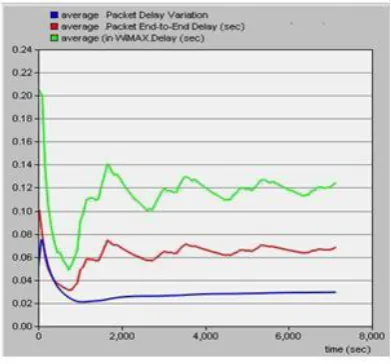
[image:5.595.330.526.97.279.2]The network used in real time to download real-time video was replicated using Opnet Modeler. SITL module of Opnet was used to import H.264 encoded real time video. Commonly-used high definition video with resolution of 1280×720 pixels, bit depth of 24, frame rate of 30 fps and Gop of size 10 was used for simu-lation. Clients consisted of 120 wired nodes and an equal number of WiMax clients. The queuing delay in the intermediate nodes was varied as per equation 9. The weakest link was at the edge router and measured 2.4 Mbps. The video was streamed using hybrid transport layer protocol approach, wherein the I frames were transmitted using TCP and the B and P frames were trans-mitted using UDP. The average stream rate of TCP was 428 Kbps and UDP was 1849 Kbps. Initial delay observed was 144 ms. Figure 5 shows the throughput of TCP and UDP stream at the receiver.
Fig. 6. Throughput at the Receiver end
SRTT was estimated for an interval of 144 ms using a recur-sive loop. The average end to end delay observed in the wired nodes was 74.86 ms. As predicted the wireless network suffered an average delay of 128.34 ms. The delay observed in the WiMax node, wired client and jitter are shown in figure 7.
Fig. 7. Delay and Jitter Measurements
[image:5.595.343.518.496.619.2]The average delay experienced in each node for a playout time of 102 minutes is shown in figure 8.The maximum delay of 6.889 ms was observed in node 7. This value of delay gives the direct measure of the buffer in each node or the target value
Fig. 8. Queuing delay in each node
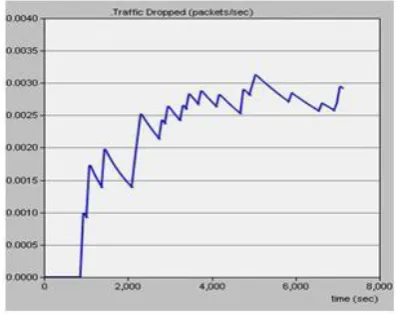
[image:5.595.76.262.593.706.2]Fig. 9. Packet loss
8. CONCLUSION
In this paper, we thoroughly investigated TCPs behavior and per-formance over the Internet. We divulge the fact that excessive buffers are available in existing networks. This does not support real-time video leading to a poor user experience. CoDel sup-ports data transmission and is suitable for networks with less number of hops. Built on top of our observations, an adap-tive Control Delay mechanism is proposed. The real network observed was simulated using Opnet Modeler. Results proved that adaptive CoDel was more suitable for transmitting real-time video.
9. REFERENCES
[1] Yaogong Wang Kyunghan Lee [1] J. Haiqing Jiang, Zeyu Liu and Injong Rhee. Understanding bufferbloat in cellular networks.Journal of Physiology, August 2012. [2] J.Gettys. Bufferbloat: Dark buffers in the internet. IEEE
Internet Computing, 50(3):96, 2011.
[3] K. c. Lan and J. Heidemann. A measurement study of cor-relations of internet flow characteristics.The International Journal of Computer and Telecommunications Networking, 50(1):46–62, 2006.
[4] B.Tiwana Z.M.Mao M.Zhang J.Huang, Q.Xu and P. Bahl. Anatomizing application performance differences on smart
phones. Proceedings of ACM MobiSys, pages 165–178, 2010.
[5] Y. Lee. Measured tcp performance in cdma 1x ev-do net-works.Proceedings of the Passive and Active Measurement Conference (PAM), pages 208–221, 2005.
[6] S. Machiraju M. Seshadri X. Liu, A. Sridharan and H. Zang. Experiences in a 3g network: Interplay between the wireless channel and applications. In Proceedings of ACM MobiCom, pages 211–222, 2008.
[7] C. Song C.Villamizar. High performance tcp in the ansnet. ACM SIGCOMM Computer Communication Re-view, 24(5):45–60, 1994.
[8] N.McKeown G. Appenzeller, I. Keslassy. Sizing router buffers. ACM SIGCOMM 04, Portland, Oregon, 34(4):281–292, September 2004.
[9] A.Goel N.McKeown M. Enachescu, Y.Ganjali and T.Roughgarden. Routers with very small buffers. Pro-ceedings of INFOCOM 2006, 25th IEEE International Conference on Computer Communications., pages 1–11, April 2006.
[10] M. K. Gardner W.-c. Feng, M. Fisk and E. Weigle. Dy-namic right-sizing: An automated, lightweight, and scal-able technique for enhancing grid performance. Proceed-ings of the 7th IFIP/IEEE International Workshop on Pro-tocols for High Speed Networks (PIHSN), pages 96–83, 2002.
[11] Kathleen Nichols and Van Jackobson. Controlling queue delay.Communications of the ACM, 55(7):42–50, 2012. [12] Iljitsch van Beijnum. Codel buffer management could solve
the internets bufferbloat jams. ars technica, May 2012. [12] http://arstechnica.com/information-technology/2012/05/ codel-buffer-management-could-solve-the-internets-bufferbloat-jams.
[13] N. S. Jayant. Effects of packet losses on waveform-coded speech. IEEE Proceedings of the 5th International Con-ference on Computer Communications, (Atlanta, Georgia), pages 275–280, October 1980.
[14] B.Palaniappan Matilda.S. Optimisation of buffer size for enhancing qos of video traffic using cross layered hybrid transport layer protocol approach. ICTACT Journal on Communication Technology, 2(1):255–264, March 2011. [15] B.Palaniappan Matilda.S. Cross layered hybrid transport