Wavelet Packet Transform Modulation for Multiple Input
Multiple Output Applications
Kelvin O. O. Anoh
Mobile and Satellite Communication Research
Centre (MSCRC), University of Bradford, UK
BD7 1DP.
R. A. Abd-Alhameed
Mobile and Satellite Communication Research
Centre(MSCRC), University of Bradford, UK
BD7 1DP.
J. M. Noras
Mobile and Satellite Communication Research
Centre(MSCRC), University of Bradford, UK
BD7 1DP.
S. M. R. Jones
Mobile and Satellite Communication Research
Centre(MSCRC), University of Bradford, UK
BD7 1DP.
ABSTRACT
An investigation into the wavelet packet transform (WPT) modulation scheme for Multiple Input Multiple Output (MIMO) band-limited systems is presented. The implementation involves using the WPT as the base multiplexing technology at baseband, instead of the traditional Fast Fourier Transform (FFT) common in Orthogonal Frequency Division Multiplexing (OFDM) systems. An investigation for a WPT-MIMO multicarrier system, using the Alamouti diversity technique, is presented. Results are consistent with those in the original Alamouti work. The scheme is then implemented for WPT-MIMO and FFT-MIMO cases with extended receiver diversity, namely 2 ×Nr MIMO systems, where Nr is the number of receiver elements. It is found that the diversity gain decreases with increasing receiver diversity and that WPT-MIMO systems can be more advantageous than FFT-based MIMO-OFDM systems.
General Terms
Wireless Communications, Digital Signal Processing, Algorithms, Performance Evaluation.
Keywords
Multiple Input Multiple Output (MIMO); Wavelet Packet Transform (WPT); OFDM; Alamouti Space Time Block Coding (A-STBC).
1.
INTRODUCTION
The use of wavelets is being adopted in the design of multicarrier modulation communication systems, for instance, in the IEEE 1901 standard for broadband Power Line Communications, as an alternative to Fast Fourier Transform (FFT) based OFDM systems [1]. Among other advantages, Wavelet Packet Transform (WPT) based multicarrier systems can operate without a cyclic prefix (CP), and offer better PAPR than FFT-OFDM systems [2].
It is accepted that OFDM with MIMO antennas can enhance data transfer rates without additional bandwidth. An example using the Alamouti two-antenna diversity scheme which includes at least two transmit antennas with up to 2-receiver antennas has been discussed in [3]. This is one method for MIMO transmissions that fully exploits the transmit power of the transmit signal [4]. Some systems in the market with MIMO technology include WiMAX (IEEE802.16e and IEEE802.16d), IEEE802.11n, UWB and HiPERLAN/2. OFDM Systems are selected for their excellent performance, namely throughput, spectral efficiency, BER and robustness against hostile multipath challenges. With combined MIMO
and OFDM, higher data rates can be achieved over the same transmit bandwidth.
Considering the stated advantages offered by the WPT when compared with the original FFT multicarrier technology in OFDM, the WPT as the base-multicarrier technology as an alternative to using the OFDM with A-STBCis proposed. Attention is focused more on the receiver diversity than the transmitter diversity, with diversity of 2×Nr, where Nr is number of receiver antennas. The results that will be shown support the use of WPT in MIMO multicarrier system implementations, but also that the diversity gains of the Alamouti scheme do not increase uniformly with increased receiver diversity.
In Section II, the OFDM and WPT for multicarrier modulation are discussed and in Section III A-STBC in the context of MIMO application will be presented. In Section IV, the simulation environment is presented. The results of simulations are presented and discussed in Section V and conclusions follow.
2.
OFDM AND WPT ARCHITECTURE
In this section, the baseband representations that characterize the MIMO system discussedis explained. The architecture is based on the WPT instead of the FFT commonly used in OFDM systems, with the motivation that the WPT scheme does not use cyclic prefixing, and offers improved PAPR with resulting benefits for power.
2.1
The FFT-OFDM
Traditional OFDM systems are based on the FFT. OFDM divides a wideband spectrum into narrow bands. The number of FFT points used gives the number of narrowband channels over which the data are transmitted. Each of the available channels is modulated by the input bits, say using BPSK. In the time-domain, the FFT-OFDM signal can be characterized as:
T t e
S N t
s T
nt j N
n
k ≤ ≤
=
∑
−
=
0 , 1
)
( 2
1
0
π (1)
)
(
,
)
(
e
s
t
S
j tCFT
ω
ω
=
where
•
represents the inner product function. Over short periods, Gabor showed that frequency components of a signal can be clearly observed by using a window,windowing operation results in the Short Time Fourier Transform (STFT) and is represented as [6]:
∫
−
=
−t
s
t
w
e
S
jwt n)
(
)
(
)
,
(
ω
τ
τ
where
w
n(
•
)
is the windowing function. This integration is done for a square-summable function whose energy must be finite for the signal to be perfectly reconstructed over a spaceR
which in this case can be approximated to represent the length of the sequence over the short time interval.2.2
The Wavelet Packet Transform (WPT)
The idea of a wavelet can be traced to the windowed STFT of Gabor discussed in [5]. It ensures translation along the time and frequency planes by shifting and scaling respectively, unlike the Fourier transform. Thus, when using the discrete wavelet transform (DWT), the observed signal is allowed variation in both time and frequency by mu
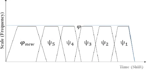
[image:2.595.60.295.394.508.2]according to the performed shifting and scaling. This property gives wavelet-based multicarrier systems signals greater robustness against high Doppler shifts than the FFT
Figure 1: Discrete wavelet scaling function and wavelets function as narrow bands
Unlike the Fourier transform that applies a constant window to the signal, the DWT uses a varied-sized windowing. This method allows for discontinuities in the signal to be identified. For instance, given that the continuous wavelet transform is represented as , () 1 ( )
a b t a t b a − =
ψ
ψ
approximations, the discrete form can be expressed
) 2 ( 2 ) ( /2
, t t n
m m n
m = −
− −
ψ
ψ
where
and are the scaling parameters, then the shifting parameters.Equation 3 can be discussed from the well-dilation equation defined as:
∑
− = n n t n ht) 2 ( ) (2 )
(
ϕ
ϕ
International Journal of Computer Applications (0975 Volume 63
(2a)
represents the inner product function. Over short periods, Gabor showed that frequency components of a signal can be clearly observed by using a window,
w
n[5]. The windowing operation results in the Short Time Fourierdt
(2b)is the windowing function. This integration is summable function whose energy must be finite for the signal to be perfectly reconstructed over a space which in this case can be approximated to represent the length of the sequence over the short time interval.
The Wavelet Packet Transform (WPT)
The idea of a wavelet can be traced to the windowed STFT of It ensures translation along the time and frequency planes by shifting and scaling respectively, unlike the Fourier transform. Thus, when using the discrete wavelet transform (DWT), the observed signal is allowed variation in both time and frequency by multiresolution according to the performed shifting and scaling. This property based multicarrier systems signals greater robustness against high Doppler shifts than the FFT [7].
scaling function and wavelets function as narrow bands
Unlike the Fourier transform that applies a constant window sized windowing. This method allows for discontinuities in the signal to be identified. ven that the continuous wavelet transform is , with some
approximations, the discrete form can be expressed [8]:
(3)
are the scaling parameters, then
and are-known two-scale
(4)
and the wavelet function,
∑
=
n
n g t) 2 ( )
(
ϕ
ψ
where
and g(n) are the low filters respectively. Equation 4is a coarser scale version of the finer scaled
shifted by “n”, with ϕ(•)as the scaling function (or the father wavelet).
If
represents the basic waveform (i.e. the scaling function from Equation 4) that can be scaled over the entire bandwidth, new waveforms can be constructinto “m” narrow bands. Each new splitting belongs to the high frequency components (usually called “wavelets”, where m = 0, 1, 2, 3,…M-2) while the remaining belong to the new
labelled as new - please see Figure 1.the last narrowband (M-1). The wavelets have h the scaling functions
have gwavelet division can be regarded
and that of the scaling function as the approximated signal
( )
AL,n then the transmitted signal is a sum of all the waveforms modulated by the input symbols expressed in Equation 6 as [9]:∑
∞∑
−∞ = = − −−
+
=
n L m L L nL
t
n
A
t
s
1 2 /,
2
(
2
)
)
(
ϕ
whereL represents the length of the corresponding filters. Notice that AL,n and Dm,n are obtained from shifting and scaling the input signal
every level, there are approximate
coefficients. The filters associated with the scaling,
wavelet,
ψ
(•) functions are finite impulse response (FIR) filters (lowpass and highpass filters respectively) of the filter bank [10]. The filters in themselves satisfy the Toeplitz matrix [11] condition and thusensure thatthe transformrobustness against channel delays.
In compact form, Equation 6can
∑ ∑
− = = k M m n k x n s 1 0 , ] [Herexk,nrepresents the nth symbol which modulates the waveform of the kth-constellation.
) (
,n t m
ϕ
represents the complex basis functionexp2
in the regular OFDM but in this case[12], is limited by the window,
=
elsewhere
n
n m0
1
,ϕ
International Journal of Computer Applications (0975 – 8887) Volume 63– No.7, February 2013
−n t ) 2 (
)
ϕ
(5)are the low-pass and the high-pass can be interpreted thus: ϕ(t) is a coarser scale version of the finer scaled ϕ(2t−n)
, as the scaling function (or the father
represents the basic waveform (i.e. the scaling function from Equation 4) that can be scaled over the entire bandwidth, constructedfrom the
by dividing into “m” narrow bands. Each new splitting belongs to the high frequency components (usually called “wavelets”,ψ
m, ) while the remaining belong to the please see Figure 1. new belongs to). The wavelets have h-filters while have g-filters. The result of the ed as the signal details
(
Dm,n)
and that of the scaling function as the approximated signalthen the transmitted signal is a sum of all the waveforms modulated by the input symbols expressed in
∑∑
= ∞ −∞ = − −−
n m m nm
t
n
D
1
2 /
,
2
ψ
(
2
)
(6)represents the length of the corresponding filters. are obtained from shifting and
. By multiresolution and at every level, there are approximate AL,nand detailD
m,n. The filters associated with the scaling,
ϕ
(
•
)
and functions are finite impulse response (FIR) filters (lowpass and highpass filters respectively) of the filter . The filters in themselves satisfy the Toeplitz matrix condition and thusensure thatthe transformed signal has robustness against channel delays.can be expressed as:
n m n
ϕ
, (t)(7)
symbol which modulates the mth -constellation.
represents the complex basis function in the regular OFDM but in this case
(a) Inverse Packet Wavelet Transform (IWPT)
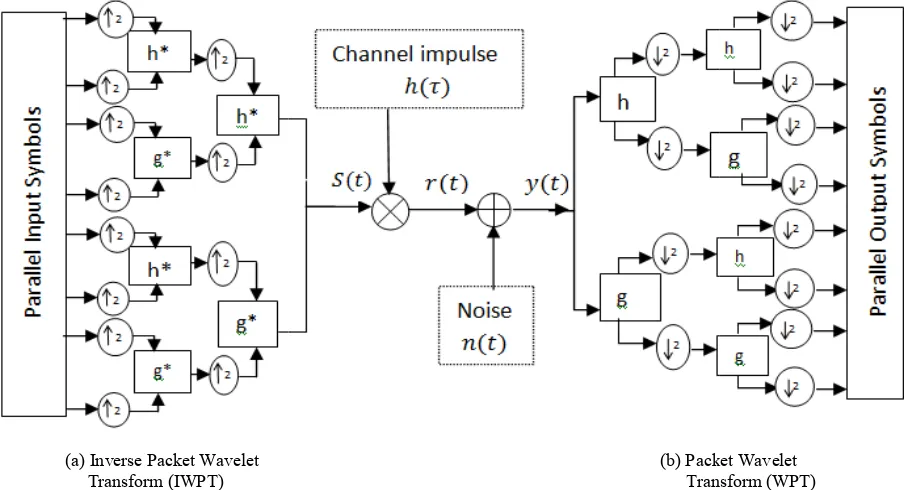
Figure 2: Implementation of WPT as a multicarrier modulation scheme
For biorthogonal wavelets, there are two basi
each wavelet. In this study, only the orthogonal wavelets which have only one basis function per wavelet
considered.
Since and are scales and shifts respectively, there exist
daughter wavelet
(
)
,•m
ψ
to transform the signaldecomposition levels, or scales. Wherein the scaling and
shifting are performed with equal magnitude, a discrete wavelet transform can then be discussed as a WPT. By definition, the synthesis WPT constructs a signal as the sum of M =2J waveforms [12], where 0
[image:3.595.54.282.602.717.2]number of possible iterations attained during implementation, whereas the analysis WPT decomposes the signal waveforms. For every scale, the data signal is first up-sampled, and then filtered by the high-pass and low-pass filters, all in the transmitter. In the receiver, the signal is decomposed, filtered by some adjacent high-pass and the low-pass filters and then down-sampled. Elsewhere in the system, any other forms of processing, e.g. coding and decoding, etc., may be applied. In compact representation, the WPT-modulated system is shown in Figure 2.
Figure 3: Implementation of OFDM for Multicarrier application
(a) Inverse Packet Wavelet (b) Packet Wavelet Transform (WPT)
Figure 2: Implementation of WPT as a multicarrier modulation scheme
For biorthogonal wavelets, there are two basis functions to orthogonal wavelets which have only one basis function per wavelet have been
are scales and shifts respectively, there exist to transform the signal at decomposition levels, or scales. Wherein the scaling and shifting are performed with equal magnitude, a discrete wavelet transform can then be discussed as a WPT. By he synthesis WPT constructs a signal as the sum represents the number of possible iterations attained during implementation, whereas the analysis WPT decomposes the signal waveforms.
sampled, and then pass filters, all in the transmitter. In the receiver, the signal is decomposed, filtered pass filters and then he system, any other forms of processing, e.g. coding and decoding, etc., may be applied. In modulated system is shown
for Multicarrier
2.3 The FFT-OFDM and WPT
Figure 3 shows an FFT-based OFDM. The OFDM operates by demultiplexing a signal sequence into orthogonal lower bits and smaller frequency component signals. These smaller orthogonal frequencies are then modulated by the simpler demultiplexed signal bits. Just after the IFFT, a cyclic prefix is used to combat the effect of the multipath channel. With WPT modulation, the IFFT/FFT and cyclic prefixing in OFDM are replaced by the IWPT/WPT described above.
3.
MIMO-WPT
USING
ALAMOUTI
STBC Scheme
The Alamouti-STBC (A-STBC) [2] involves transmitting two different signal streams ( and
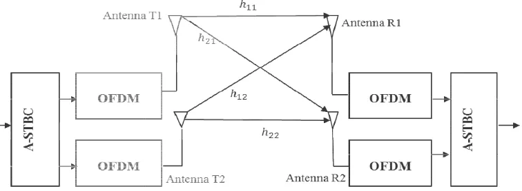
transmit antennas at some two different time slots, the system assumed to be constant over two symbol periods. Signal streams (and ) are transmitted in the first symbol period, and conjugates of these signals are transmitted in the second symbol period. Figure 4 shows the OFDM
modulation architecture based on the A this is replaced with the WPT. In the first time be transmitted using antenna T1 of Figure 4 and
antenna T2. In the second time period, the negative conjugate of s2, i.e. (
−
s
*2), and the conjugate ofantennas T1 and T2 respectively.
In this scheme each symbol will appear equally as likely as the original signal, and, in that case, the signals will be expressed as [4]:
* 5 . 0
1 s
s =
* 5 . 0
2 s
s =
1
s ands2and their conjugates ( with the channel impulse responses
(b) Packet Wavelet Transform (WPT)
Figure 2: Implementation of WPT as a multicarrier modulation scheme
OFDM and WPT-OFDM Modulations
based OFDM. The OFDM operates by demultiplexing a signal sequence into orthogonal lower bits and smaller frequency component signals. These smaller orthogonal frequencies are then modulated by the simpler signal bits. Just after the IFFT, a cyclic prefix is used to combat the effect of the multipath channel. With WPT modulation, the IFFT/FFT and cyclic prefixing in OFDM are replaced by the IWPT/WPT described above.
WPT
USING
ALAMOUTI-STBC) [2] involves transmitting two and ) using two different transmit antennas at some two different time slots, the system assumed to be constant over two symbol periods. Signal transmitted in the first symbol period, and conjugates of these signals are transmitted in the second symbol period. Figure 4 shows the OFDM- MIMO modulation architecture based on the A-STBC. In Figure 5, this is replaced with the WPT. In the first time period,
s
1will be transmitted using antenna T1 of Figure 4 and s2using antenna T2. In the second time period, the negative conjugate ), and the conjugate of s1, i.e. s1* , over antennas T1 and T2 respectively.In this scheme each symbol will appear equally as likely as the original signal, and, in that case, the signals will be
) (t
s (6a)
) (t
s (6b)
Figure 4: Implementation of Alamouti
1 2 1
1
n
s
s
H
r
+
=
and,
2 * 1 * 2
2 n
s s H
r +
− =
where !" = #
⋮ ⋮ %& %&
[image:4.595.122.472.457.598.2]In this work, the number of receive antenna Nr has been limited to 5, and signals received will be passed to the Maximum Likelihood-Decoding (MLD) stages of the system
Figure 5: Alamouti Scheme in MIMO
4.
SIMULATION ENVIRONMENT
The system was designed for raw bits (that is, uncoded bits). It involved a processing of 2560000 symbols, decomposed using eight levels with the db2
family to achieve full transmission points equivalent to the number of narrow-bands provided by the FFT by WPT. db2 wavelets are orthogonal wavelets which use the same filters for signal decomposition and reconstruction. As in Figure 2, the filters are used to achieve the time domain signals described in Equation 6. The A-STBC was then applied toachieve up to two transmitter diversity. Notice tha STBC method assumes that the channel state is completely
International Journal of Computer Applications (0975 Volume 63
Figure 4: Implementation of Alamouti Scheme in MIMO-OFDM using FFT/IFFT with cyclic prefixing
(7a)
(7b)
' (8)
In this work, the number of receive antenna Nr has been limited to 5, and signals received will be passed to the Decoding (MLD) stages of the system
discussed in [3]. This MLD estimates the signal whose Euclidean distance is closest to the transmitted symbol. In and [13], the mathematical complexities associated with the MLD and decision making on the most probable s decode has been simplified to:
2 1 1 1
h
r
r
d
=
H+
H and,2 1 2 2
h
r
r
d
=
H−
Hwhere
( )
⋅H denotes a Hermitian(9b) represent the decoded bits to be compared with the transmitted bits for error assessment. By the schemes explained in the foregoing discussion, a simulation was carried out as explained in the next section
Figure 5: Alamouti Scheme in MIMO-WPTM Architecture
SIMULATION ENVIRONMENT
The system was designed for raw bits (that is, uncoded data bits). It involved a processing of 2560000 symbols, decomposed using eight levels with the db2-wavelet sub-family to achieve full transmission points equivalent to the
bands provided by the FFT by WPT. db2-elets which use the same filters
reconstruction. As in Figure 2, the filters are used to achieve the time domain signals STBC was then applied achieve up to two transmitter diversity. Notice that the A-STBC method assumes that the channel state is completely
known to the transmitter hence, training symbols may not be required in the channel design. In the receiver, the receiver diversity was increased to 5-antenna configuration to assess the diversity behavior of the A
two receiver elements. A Rayleigh fading channel was createdwith some additive white Gaussian noise (AWGN). Then, with the A-STBC described above,
study is investigated for 2x1, 2x2, 2x3,
QAM. In other words, up to 2x5 MIMO WPT has been considered. It is assumed that during transmission, the channel is quasi-staticfor two symbol periods
International Journal of Computer Applications (0975 – 8887) Volume 63– No.7, February 2013
OFDM using FFT/IFFT with cyclic prefixing
. This MLD estimates the signal whose Euclidean distance is closest to the transmitted symbol. In [4] , the mathematical complexities associated with the MLD and decision making on the most probable signal to
2
h
H(9a)
1 2
h
H
(9b)
denotes a Hermitian operator. Equations (9a) and (9b) represent the decoded bits to be compared with the transmitted bits for error assessment. By the schemes explained in the foregoing discussion, a simulation was carried out as explained in the next section.
known to the transmitter hence, training symbols may not be required in the channel design. In the receiver, the receiver antenna configuration to assess rsity behavior of the A-STBC method for more than . A Rayleigh fading channel was createdwith some additive white Gaussian noise (AWGN). STBC described above, the design in this investigated for 2x1, 2x2, 2x3, 2x4 and 2x5 for 4-QAM. In other words, up to 2x5 MIMO WPT has been considered. It is assumed that during transmission, the channel
5.
RESULT AND DISCUSSION
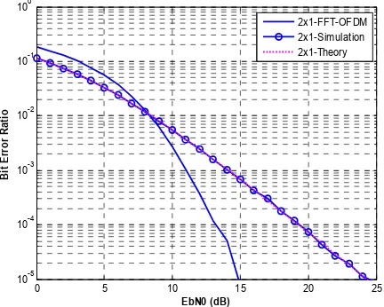
[image:5.595.56.272.153.326.2]In Figure 6, it is demonstrated that the simulation is consistent with theoretical results. Random data were generated, mapped using BPSK, then the system was simulated and results compared with the theoretical result of the Alamouti 2x1-MIMO scheme.
Figure 6: Comparing Alamouti 2x1-Simulation and Theoretical Results
Figure 6 shows that our simulation consistently agreed with theory, for Alamouti 2x1. Results were further compared with the Alamouti 2x1-OFDM: this showed better performance using OFDM, as cyclic prefixing helps reduce errors due to inter-symbol interference (ISI). Figure 7 further reports cases of 2x2, 2x3, 2x4 and 2x5 A-STBC OFDM results for receiver diversity investigation.
Figure 7: Results of A-STBC 4-QAM MIMO-WPTModulation
In Figure 7, the case of FFT and WPT in terms of BER using the above parameters and the A-STBC schemewas compared. For fair comparison both simulations were carried out using the same parameters and environment. While there are slight performance gains along the increasing receiver diversity configurations, it can be observed that the WPT advantage over FFT becomes more pronounced for 3, 4 and 5-receiver elements.
Unarguably, the MIMO-WPT outperforms the FFT-OFDM MIMO system. As expected, the performance of our system improves with receiver diversity, i.e. the number of receive antennas. It is interesting to note that the scheme’s diversity depletes with increased receiver diversity. For instance, if the result in Figure 7 is observed for 2x2-antenna configuration using 4-QAM at 10-4 BER, up to 3.5 dB gain was achieved comparing with the 2x3-antenna configuration, but with 2x3 and 2x4, there is nearly 2.0 dB performance difference in favor of 2x3. Lastly comparing the 2x4 with 2x5, there is only about 1.3 dB performance gain. It is interesting also that the Alamouti space-time scheme may not perform well for diversity order higher than those observed here. Hence, for systems with a greater order of receiver diversity, other forms of space-time codes should be preferred. Note that the 2x5 FFT performed almost like the 2x4 WPT.
6.
CONCLUSION
From the ongoing discussion, it was shown that, inasmuch as FFT can be used to implement the OFDM multicarrier system with MIMO, it is also possible to implement the MIMO-multicarrier system using the WPT. Besides saving bandwidth, the use of WPT is favored in multicarrier systems design, as shown in Figure 7. With increased receiver diversity, the 2x4 MIMO-WPT performed similarly as 2x5 MIMO-FFT. By simulation however, it was shown that WPT-MIMO systems can be preferred over FFT-WPT-MIMO systems. It was shown that the diversity gain of the Alamouti scheme decreases with increased number of antennas in the receiver. This may be overcome by considering other forms of space-time coding mechanisms. To further investigate this, other forms of space-time coding techniques can be explored
.
7.
ACKNOWLEDGMENTS
This work has been fully funded by the Ebonyi State Government of Nigeria. The authors are deeply thankful to the governor of the state – Chief Martin N. Elechi.
8.
REFERENCES
[1] S. Galli, H. Koga, and N. Kodama, "Advanced signal processing for PLCs: Wavelet-OFDM," IEEE International Symposium onPower Line Communications and Its Applications, 2008. ISPLC 2008, pp. 187-192. [2] M. Hoch, S. Heinrichs, and J. B. Huber,
"Peak-to-average power ratio and its reduction in wavelet-OFDM," in International OFDM Workshop, 2011, pp. 56-60.
[3] S. M. Alamouti, "A simple transmit diversity technique for wireless communications," IEEE Journal on Selected Areas in Communications, vol. 16, pp. 1451-1458, 1998. [4] A. Goldsmith, Wireless communications: Cambridge
university press, 2005.
[5] J. Yao, P. Krolak, and C. Steele, "The generalized Gabor transform," IEEE Transactions onImage Processing, vol. 4, pp. 978-988, 1995.
[6] M. Vetterli and C. Herley, "Wavelets and filter banks: Theory and design," IEEE Transactions onSignal Processing, vol. 40, pp. 2207-2232, 1992.
[7] M. Oltean, "Wavelet OFDM performance in flat fading channels," Scientific Bulletin of University Politehnica Timisoara, ETC Series, vol. 52, pp. 167-172, 2007.
0 5 10 15 20 25
10-5 10-4 10-3 10-2 10-1 100
EbN0 (dB)
B
it
E
rr
o
r
R
a
ti
o
2x1-FFT-OFDM 2x1-Simulation 2x1-Theory
0 2 4 6 8 10 12 14 16
10-5 10-4 10-3 10-2 10-1 100
EbN0 (dB)
B
it
E
rr
o
r
R
a
ti
o
[image:5.595.57.276.442.641.2]International Journal of Computer Applications (0975 – 8887) Volume 63– No.7, February 2013
[8] I. Daubechies, Ten lectures on wavelets vol. 61: SIAM, 1992.
[9] K. Abdullah, "Interference Mitigation Techniques for Wireless OFDM," RMIT University, 2009.
[10] M. Weeks, Digital Signal Processing Using MATLAB & Wavelets: Jones & Bartlett Learning, 2010.
[11] G. Strang, "Lowpass and Highpass – Lecture 24 of 32 " in Discrete Filters, ed: Academic Earth.
[12] A. Jamin and P. Mähönen, "Wavelet packet modulation for wireless communications," Wireless Communications and Mobile Computing, vol. 5, pp. 123-137, 2005. [13] J. Proakis and M. Salehi, Digital Communications, Fifth