ISSN Online: 1947-3818 ISSN Print: 1949-243X
Practical Equivalent Method of Power
Network Based on PSASP Short-Circuit
Calculation Program
Haini Qu
1, Mingnian Li
2, Xiu Yang
2, Pengfei Zhang
11State Grid Electric Power Research Institute, SMEPC, Shanghai, China
2Shanghai University of Electric power, School of Electrical Engineering, Shanghai, China
Abstract
When using the ATP-EMTP software to simulate the electromagnetic tran-sient of local line or nearby line for a large area power grid, it is necessary to divide the area grid into internal network and external network so as to make the external network simple for the restriction of the simulation calculation scale of software. Based on the existing equivalence method, in this paper we proposed a practical equivalent method using the short-circuit calculation program of PSASP. In this way, we completed the equivalence of northwest power grid operating at the large mode of summer 2016. By comparing the power flow and the characteristics of short-circuit in the system before and after the equivalence, this equivalent method is proved to be correct.
Keywords
PSASP, Short-Circuit Calculation, Practical Equivalence
1. Introduction
With the construction of UHV grid and the gradual interconnection and marke-tization of power systems, the size of the national synchronous power grid will be bigger and bigger. Limited to the simulation calculation scale of software, such a large power system simulation calculation, stability research, and analysis will become increasingly difficult. Therefore, in the actual engineering calcula-tion, it is important to focus on the regional which is required research and analysis, and to reduce the scale of the project and reduce the contradiction of accuracy and speed of the simulation software. As more and more power plants and 750 kV lines constructed in Urumqi power grid, the short-circuit current is
How to cite this paper: Qu, H.N., Li, M.N., Yang, X. and Zhang, P.F. (2017) Practical Equivalent Method of Power Network Based on PSASP Short-Circuit Calculation Program. Energy and Power Engineering, 9, 683-692.
https://doi.org/10.4236/epe.2017.94B074
getting bigger and bigger, for this to cascade reactor to resist short-circuit cur-rent. But the series reactor will also affect the DC component of the short-circuit current and the transient recovery voltage of circuit breaker, thereby affecting the breaking performance of circuit breaker. So, it needs to have an electromag-netic transient simulation of Urumqi power grid. There are 9906 nodes and 10888 lines in the PSASP database of the Northwest Power Grid, and the data of the grid is too big. The establishment of the Urumqi electromagnetic transient simulation model needs to be simplified for its surrounding power grid. In this paper, we first introduce the common static and dynamic power grid equivalent method, and then propose a practical method based on PSASP short circuit cur-rent calculation program. By comparing the power flow and the short-circuit current level of the critical line nodes between the equivalent and the original system, it shows the validity and practicability of the equivalent method. By us-ing the equivalent parameters and PSASP raw data, a detailed electromagnetic transient simulation model of Urumqi city power grid is set up, which lays a solid foundation for the further study on the influence of the series reactance of Urumqi power line on the breaking characteristics of circuit breaker.
2. Introduction of Commonly Used Methods
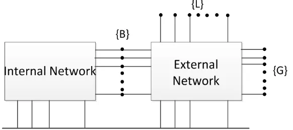
When a part of a large-scale interconnected power system is analyzed and stu-died, the part concerned is referred to as the internal network, and only the im-pact on the internal network needs to be considered in other areas. So, it is not necessary to describe the other areas in detail. This part is called an external network. The large-scale power system is divided into internal network and ex-ternal network shown in Figure 1.
[image:2.595.228.519.589.718.2]In Figure 1, {B} denotes the boundary node, {G} denotes the external network generator node, and {L} denotes the external network load node. Before the equivalence, the internal network and the external network are connected through the boundary nodes. After the equivalence, the external network is sim-plified and the internal network is connected to the outer network equivalent model through the boundary node. According to the purpose of the study, the equivalent method can be divided into two types of static equivalence and dy-namic equivalence [1].
2.1. Static Equivalence Method
The static equivalent method is based on the simplification of the algebraic equ-ation, which is mainly used to deal with the steady state problem of the large- scale power system. At home and abroad, a lot of research has been carried out from the perspective of power flow calculation [2]. Common static equivalence methods are ULF, WARD, and REI. The equivalence model of the external sys-tem in the ULF method is the power flow, and the power flow equivalent of the external system needs to be solved first. This is not the same as the following two methods and it is not commonly used in practice [3]. WARD equivalence and REI equivalence methods need to establish the external network node voltage equation, through the Gaussian elimination method to simplify the external network. When the equivalent network has thousands of nodes, the simplified calculation of the workload is huge. These methods are now more common in theoretical research, and are not widely used in the large-scale power grid engi-neering practice.
2.2. Dynamic Equivalence Method
The simplified process of external network based on the fact that the main dy-namic features of the internal system are not distorted are called dydy-namic equi-valence [4]. Dynamic equiequi-valence is mainly concerned with the influence of ex-ternal system on the dynamic response process of the inex-ternal system. It is ap-plied to off-line transient stability analysis, dynamic safety analysis and stability control device design of large-scale power system [5]. The dynamic equivalence involves the transient process of the power system, which is based on the simpli-fication of the differential algebraic equation. At present, the main dynamic equivalence methods include cohomology equivalence method, model equiva-lence method and estimated equivaequiva-lence method.
Based on the generator’s cohomology features, cohomology equivalence me-thod is used to analyze the transient stability under large disturbance. The most important thing to apply the cohomology equivalence method is to judge the cohomology of the generator. In engineering practice, there is little strict coho-mology. According to different circumstances, different cohomology criteria should be applied. [6] [7] [8].
The model equivalence method reduces the computational complexity by re-ducing the number of differential equations in the transient equation. The ma-thematical logic and the physical concept of this equivalent method is clear and the calculation is simple. However, the linear simulation of the external system will bring a great error to the transient process analysis, so it is only applicable to the dynamic stability analysis under the small disturbance.
3. Practical Equivalent Method
3.1. Equivalent Principle
As with the above equivalent method, the large-scale power system network is divided into two parts, internal and external networks, which are connected by boundary nodes. In order to ensure the simplified equivalent system can main-tain the characteristics of the original system, whole process should satisfy the following conditions:
The power flow of the internal system before and after the equivalence re-mains unchanged;
Before and after the equivalence of the grid, the bus node short-circuit current level remains unchanged [11].
For external networks, due to the difference in the ability to contribute to short-circuit currents due to different voltage levels, the voltage of power grid which is 220 kV and above is simplified as a voltage source connects a reactance with the internal system, and the voltage of power grid which is 110 kV and be-low is simplified as a load model connected with the internal network.
For example, with a system with only four boundary nodes, the overall system is simplified as shown in Figure 2.
3.2. Equivalent Parameter Determination
This section takes a node as an example to illustrate the calculation of a class of boundary nodes parameters.
Load model parameters. In order to ensure the consistency of the power flow of the system before and after the equivalence, the outgoing power flow of the nodes are counted and accumulated as the total load to the boundary nodes, as in
[image:4.595.228.521.554.716.2](1) The load model is selected according to the typical model of the load node near the equivalent system of the node. The parameters are selected as the typi-cal parameters of the equivalent load nodes.
The equivalent reactance value. For the three-phase symmetrical short circuit calculation, the short-circuit current value and the short-circuit current dis-tribution coefficient [12] can be obtained, and the short-circuit current value of each branch at the nodes can be obtained by multiplying the total short- circuit current and the distribution coefficient. In order to ensure the same size of the boundary bus short-circuit current before and after equivalence, the formula for calculating the equivalent reactance can be obtained as fol-lowing:
1 s
x=
∑
i (2)s
i is the sum of short-circuit current of branch which is the external system
connected to the boundary node. The amount of each volume is per unitary val-ue.
Generator parameters. The power flow and phase angle of the boundary nodes are obtained by calculating the power flow of the pre- equal system. The type of the generator nodes bus is selected as slack, and the amplitude and phase angle of the nodes voltage are the same as the equivalent large network. The generator model is chosen as a E′ constant classical second order model
with its d-axis transient reactance xd′ value as the resistance value obtained
by Equation (1)
d
x′ =x (3)
Since only three-phase symmetrical short-circuit is considered, the negative sequence reactance is the same as the positive sequence reactance value:
2 d
x =x′ (4)
Ignoring the rotor inertia on the transient short-circuit current effect, the ro-tor inertia time is to take infinity:
j
T = ∞ (5)
3.3. Evaluation of the Equivalent Method
In order to ensure the accuracy of the internal network when the large network is divided into internal and external network, it is necessary to determine the error of the voltage and phase angle of the line nodes before and after the equi-valence. And it needs to observe whether the error is within the acceptable range. On the basis of the correct structure of the grid, the reliability of the equivalent is ensured by comparing the short-circuit current value of the reserved nodes be-fore and after the equivalence.
Both of the evaluation indicators are equal to the relative deviation of the ab-solute value of less than 5%, as in
1 2
1
-5%
x x
x
∆ = ≤ (6)
In this formula, x1 is the value of the line voltage, phase angle and short-
circuit current before the equivalence, and x2 is the value of the line voltage,
4. Actual Grid Equivalent Process
4.1. Determination of Equivalence Range
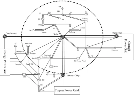
In this paper, the northwest power grid in 2016 summer operation data is the original grid data. The power grid whose voltage is 220 kV and above in Urumqi is shown in Figure 3. In which Wubei-Ganshi Power Plant lines, Chemical In-dustry Park—Huatai Thermal Power Plantlines, Chemical InIn-dustry Park—Tian- chi Power Plant line, Xinfayiqi—Longgang line, Tairui Power Plant—Taiheng line, Lukang Power Plant—Linmin line is the follow-up focus on simulation analysis of the line, and the circle is the network retained.
According to the scale of retaining external network station, the international network modeling will be roughly divided into three kinds [13].
Direct equivalence model. The network outside the study area is equivalent to a smaller equivalent network directly. The process is simple, but the accuracy is not high.
The detailed model of a little external network station is kept as the buffer network, and the other parts of the external network are equalized. The equiv-alent effect of the method is better than method 1.
The details of the external network structure and parameters of the simplified model are retained. This method has a high modeling accuracy, but difficult to build a simulation.
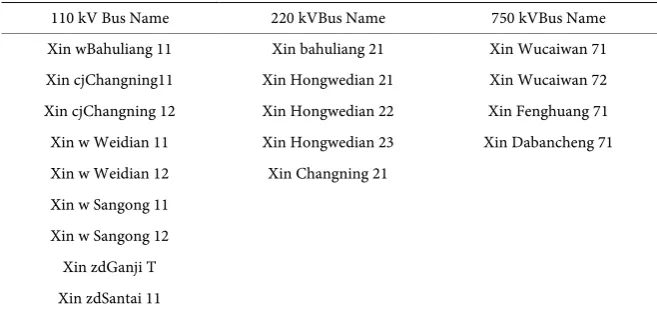
Figure 3 shows the Chemical Plant, Ganshi Power Plant, Huatai Thermal Power which are follow-up focused plants. And these plants is closely connected to the original external system. To reduce the error of the simulation model, it needs to select the buffer model to correct the equivalent boundary. So, we put the Changning Substation, Sangong Substation, Bahuliang Substation and some lines into the buffer network. 18 boundary nodes are selected according to dif-ferent voltage levels. The specific boundary nodes are shown in Table 1.
4.2. Equivalent Model Construction
[image:6.595.209.538.577.733.2]Based on the boundary nodes identified above, the reserved and buffered net-works (hereinafter referred to as the internal network) and the external network
Table 1. Equivalent boundary nodes.
110 kV Bus Name 220 kVBus Name 750 kVBus Name Xin wBahuliang 11 Xin bahuliang 21 Xin Wucaiwan 71 Xin cjChangning11 Xin Hongwedian 21 Xin Wucaiwan 72 Xin cjChangning 12 Xin Hongwedian 22 Xin Fenghuang 71 Xin w Weidian 11 Xin Hongwedian 23 Xin Dabancheng 71 Xin w Weidian 12 Xin Changning 21
Figure 3. The power grid whose voltage is 220 kV and above in Urumqi.
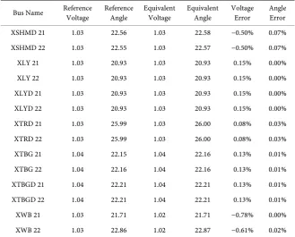
are isolated from the PSASP software in the form of a three-phase disconnection fault. Since there is no data conversion program between PSASP and ATP- EMTP, the PSASP database file should be exported and re-modeled in ATP. It needs to count the transmission power flow which is from the boundary nodes to the external network and then accumulates it as the total load value connected to the border nodes. As the outgoing power may be negative, and PSASP soft-ware load model parameters cannot identify the “negative load”, it is necessary to flexibly select the load or fixed PQ generator model at the boundary nodes according to the positive or negative load. In order to ensure the integrity of the internal network, the power flow of the network before and after the equivalent should be compared. The bus voltage phase and angle of the network before and after the equivalence are shown in Table 2. The bus name is abbreviated in the table and the unit of the voltage is p.u.
It can be seen from the Table 2 that the bus voltage amplitude error of the area focused on before and after equivalent is less than 0.5%. And bus voltage phase angle error is 0.1% or less. The error is within the acceptable range.
4.3. Determination of Equivalent Parameters
Table 2. The power flow of the network before and after the equivalent.
Bus Name Reference Voltage Reference Angle Equivalent Voltage Equivalent Angle Voltage Error Angle Error
XSHMD 21 1.03 22.56 1.03 22.58 −0.50% 0.07%
XSHMD 22 1.03 22.55 1.03 22.57 −0.50% 0.07%
XLY 21 1.03 20.93 1.03 20.93 0.15% 0.00%
XLY 22 1.03 20.93 1.03 20.93 0.15% 0.00%
XLYD 21 1.03 20.93 1.03 20.93 0.15% 0.00%
XLYD 22 1.03 20.93 1.03 20.93 0.15% 0.00%
XTRD 21 1.03 25.99 1.03 26.00 0.08% 0.03%
XTRD 22 1.03 25.99 1.03 26.00 0.08% 0.03%
XTBG 21 1.04 22.15 1.04 22.16 0.13% 0.01%
XTBG 22 1.04 22.16 1.04 22.16 0.13% 0.01%
XTBGD 21 1.04 22.21 1.04 22.21 0.13% 0.01%
XTBGD 22 1.04 22.21 1.04 22.21 0.13% 0.01%
XWB 21 1.03 21.71 1.02 21.71 −0.78% 0.00%
XWB 22 1.03 22.86 1.02 22.87 −0.61% 0.02%
are determined according to the typical parameters of the nodes near the region. For some boundary nodes like Xin w Weidian11(name of the node defined in PSASP, the same below), Xin w Weidian 12, Xin zdGanji T, Xin zd Santai11, the specific values are 20% constant impedance + 80% constant power load con-nected to the internal network. For some boundary nodes like Xin cj Changn-ing11, Xin cj Changning 12, Xin w Sangong11, Xin w Sangong12, the specific values are 30% constant impedance + 70% constant power load connected to the internal network.
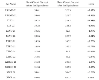
Table 3. The short current value of the network before and after the equivalent.
Bus Name before the Equivalence Short Circuit Current Short Circuit Current after the Equivalence Error
XSHMD 21 33.61 32.93 −2.02%
XSHMD 22 33.64 32.97 −1.99%
XLY 21 33.28 32.62 −1.98%
XLY 22 33.28 32.62 −1.98%
XLYD 21 33.26 32.6 −1.98%
XLYD 22 33.26 32.59 −2.01%
XTRD 21 14.93 14.52 −2.75%
XTRD 22 14.93 14.52 −2.75%
XTBG 21 31.86 31.2 −2.07%
XTBG 22 31.86 31.2 −2.07%
XTBGD 21 31.38 30.73 −2.07%
XTBGD 22 31.38 30.73 −2.07%
XWB 21 50.61 50.47 −0.28%
XWB 22 44.64 44.72 0.18%
It can be seen from the Table 3 that the nodes short-circuit current level of the area focused on is basically the same. The error is less than 3%, which is within the acceptable range. The equivalent network can meet the needs of sub-sequent electromagnetic transient simulation.
5. Conclusions
Based on the PSASP short-circuit current calculate program, the practical equiv-alent method of the power network is realized, which realizes the identification of external network parameters. By using this method, the equivalent simplifica-tion of the Northwest power grid is completed. The feasibility of the equivalent method is verified by comparing the power flow and short circuit between the power grid before and after the equivalence.
At the same time, this method also has its shortcomings. It cannot determine the negative sequence parameters and zero sequence parameters of the equiva-lent reactance. So, it cannot achieve asymmetric electromagnetic transient si-mulation in EMTP program, which needs to be further studied.
References
[1] Wen, M.H. and Yang, F. (2012) An Equivalence Method of Regional Power Net-work Based on Short Circuit Calculation by Power System Analysis Software Pack-age. Power System Technology, 1, 113-117.
[2] Zhang, B.M., Chen, S.S., Yan, Z. (2007) Analysis of Higher Power Networks. 2th Edition, Tsinghua University Press, Beijing.
[4] Ni, Y.X., Chen, S.S. and Sun, B.L. (2001) Theory and Analysis of Dynamic Power System. Tsinghua University Press, Beijing.
[5] Liu, F. (2007) Elementary analysis of external network equivalence. Relay.15, 67-71. [6] Peng, W. and Xu, T.S. (2010) A Generator Selection Method for Power System
Dy-namic Equivalents. Automation of Electric Power System, 14, 48-51.
[7] NATH R. (1985) Coherency Based System Decomposition into Study and External Areas Using Weak Coupling. IEEE Trans on Power Apparatus and System, 6, 1443-1449. https://doi.org/10.1109/TPAS.1985.319158
[8] Wen, J., Liu, T.Q. and Li, X.Y. (2008) On-line Identification of Coherent Generator Using Optimized LS-SVM, Proceeding of the CSEE, 25, 80-85.
[9] Chen, H., Deng, C.H. and Li, D.L. (2008) Recurrent Neural Network-based Dy-namic Equivalencing and Identification. High Voltage Engineering, 5, 1001-1004. [10] Zhou, Y.H., Li, X.S. and Hu, X.Y. (1999) Dynamic Equivalents Based on the
Tran-sient Power Flow of the Connecting Lines. Proceeding of the EPSA, 5, 29-33. [11] Wang, R.X. (2012) Study on Dynamic Equivalent Method of AC-DC Hybrid Large
Power Network. M.S. Thesis, Shanghai University of Electric Power, Shanghai. [12] Power System Analysis Software Package Short Circuit Calculate User’s Manual.
(2001), 31-34. China Electric Power Research Institute, Beijing.
[13] Kato, K. External Network Modeling-recent Practical Experience. (1994) IEEE Trans on Power System. 1, 216-228.
Submit or recommend next manuscript to SCIRP and we will provide best service for you:
Accepting pre-submission inquiries through Email, Facebook, LinkedIn, Twitter, etc. A wide selection of journals (inclusive of 9 subjects, more than 200 journals)
Providing 24-hour high-quality service User-friendly online submission system Fair and swift peer-review system
Efficient typesetting and proofreading procedure
Display of the result of downloads and visits, as well as the number of cited articles Maximum dissemination of your research work
Submit your manuscript at: http://papersubmission.scirp.org/