University of Southampton Research Repository
ePrints Soton
Copyright © and Moral Rights for this thesis are retained by the author and/or other copyright owners. A copy can be downloaded for personal non-commercial
research or study, without prior permission or charge. This thesis cannot be
reproduced or quoted extensively from without first obtaining permission in writing from the copyright holder/s. The content must not be changed in any way or sold commercially in any format or medium without the formal permission of the
copyright holders.
When referring to this work, full bibliographic details including the author, title, awarding institution and date of the thesis must be given e.g.
University of Southampton
Faculty of Engineering and Applied Science
Department of Electronics and Computer Science
Southampton SO17 1BJ
A Graphically based language for constructing, executing and analysing models of
software systems
by
Robert John Walters
A thesis submitted for the degree of Doctor of Philisophy
UNIVERSITY OF SOUTHAMPTON
ABSTRACT
FACULTY OF ENGINEERING AND APPLIED SCIENCE
ELECTRONICS AND COMPUTER SCIENCE
Doctor of Philosophy
A graphically based language for constructing, executing and analysing models of
software systems
by Robert John Walters
With computer systems becoming ever larger and more complex, the cost and ef-fort associated with their construction is increasing. Consequently, it is more im-portant than ever that the developers understand how their systems behave if prob-lems are to be avoided. However, acquiring this understanding is a problem: the systems are sufficiently complex that developers need help to analyse and under-stand them and, at the time this analysis is most crucial, the system is unavailable because it has yet to be built.
We already have maturing technologies which address issues associated with the interconnection of software components at the procedural level, but they do not address issues related to the behaviour of these compound systems. Formal, ex-ecutable models can help here by providing developers with a platform on which to establish the feasibility of a proposed design for a system. However, commer-cial developers seem reluctant to employ this type of modelling in their design activity.
Acknowledgements
I would like to acknowledge the help, support and encouragement which I have
received from family, friends, colleagues and others whilst pursuing this work. In
particular, I am indebted to my supervisor, Peter Henderson for his support and
encouragement over the years.
Of the others, I hesitate to name names in case I should miss someone out. Let me
just say this: you know who you are and I appreciate your help and support.
Contents
ABSTRACT ... 2
Acknowledgements ... 3
Contents ... 4
List of Figures... 10
Chapter 1 Overview... 13
1.1 Why build executable models?... 13
1.2 Desirable features of a modelling system... 16
Chapter 2 History and background ... 21
2.1 Background... 21
2.2 Essential features of effective modelling systems ... 28
2.3 Characteristics of modelling systems ... 29
2.3.1 Formal-informal... 29
2.3.2 Graphical/textual ... 29
2.3.3 Communications paradigm... 29
2.3.4 Objective... 32
2.4 Existing systems ... 32
2.4.1 UML ... 32
2.4.2 Rapide/Darwin/Wright ... 33
2.4.3 Process Algebras and Model checking ... 33
2.4.4 CSP/FDR ... 34
2.4.5 FSP/LTSA ... 35
2.4.6 ALLOY... 35
2.4.7 Pi-Calculus... 36
2.4.8 SPIN... 36
2.4.9 RADs ... 37
2.4.10 RolEnact ... 39
2.5 Conclusion ... 40
Chapter 3 RolEnact/RaDraw/ARE ... 42
3.1 What is RolEnact? ... 42
3.1.2 Interaction ... 43
3.1.3 Selection ... 44
3.1.4 Creation/Create ... 44
3.2 Analysis of RolEnact ... 46
3.2.1 “Style” of RolEnact code... 46
3.2.2 The communications paradigm ... 46
3.2.3 The semantics of select... 46
3.2.4 Opaque communications ... 47
3.3 RaDraw ... 48
3.4 ARE ... 50
3.5 Further potential enhancements to RolEnact... 51
Chapter 4 The RDT notation ... 53
4.1 Rationale of the language ... 53
4.2 The classes/instances problem... 55
4.3 Description of the language ... 56
4.3.1 Describing Processes ... 57
4.3.1.1. Send ... 59
4.3.1.2. Receive ... 60
4.3.1.3. Create... 61
4.3.2 Constructing Processes ... 62
4.3.3 Describing Models... 64
4.3.3.1. Instances ... 64
4.3.3.2. Connections ... 66
4.4 Using the language ... 67
4.4.1 The Barbershop... 67
4.4.2 Project Management ... 71
Chapter 5 Practical application of the RDT language ... 76
5.1 Construction of a model ... 76
5.2 Analysis of the model ... 78
5.2.1 Initial considerations... 79
5.2.2 By execution ... 80
5.3 Presentation of a model ... 82
Chapter 6 A translation into the pi-calculus ... 83
6.1 An outline of the pi-calculus ... 83
6.2 A mapping from RDT to Pi-calculus... 88
6.2.1 RDT processes to pi-calculus: ... 88
6.2.2 RDT "models" to pi-calculus:... 90
Chapter 7 Transforming RDT models for analysis ... 94
7.1 Selecting a target model checker ... 94
7.2 An outline of SPIN and Promela ... 95
7.2.1 IF... 97
7.2.2 DO ... 97
7.2.3 Communications in Promela ... 98
7.2.4 Initialising a model ... 99
7.3 Considerations in mapping from RDT to Promela... 99
7.4 How RDTtoSPIN performs its conversion ... 101
7.5 The problem of "Create"... 102
7.6 One further minor matter ... 103
Chapter 8 Communications in models... 105
8.1 A model demonstrating communications in RDT... 105
8.2 Building an equivalent model in FSP ... 109
8.3 An improved model in FSP ... 112
8.4 Summary... 114
Chapter 9 Experiments and examples ... 115
9.1 The simplest model... 115
9.2 A second example model... 122
9.3 Defence ... 127
9.3.1 Outline of the “real” system ... 127
9.3.2 MQDefence Models in RDT without Communications... 128
9.3.3 Adding communications to MQDefence Models in RDT... 135
9.4 Banking... 136
9.4.1 “WebATM” ... 136
9.4.3 The “inbox” architecture ... 140
9.4.4 Deadlock in WebATM and the “inbox” architecture ... 141
9.5 “Mobile Telephones”... 143
9.6 Using RDT... 153
9.6.1 Approachability ... 153
9.6.2 Size and ease of learning ... 154
9.6.3 Capability... 154
9.6.4 Providing a smooth path to using “heavy-weight” formal methods... 155
Chapter 10 Conclusion and further work ... 156
10.1 Reflection... 159
10.2 Potential enhancements to RDT ... 163
10.3 Improvements to the RDT tools ... 164
Appendix A Example models in XML... 166
A.1 Defence (without communications)... 166
A.2 Defence (with communication) ... 168
A.3 Banking... 171
A.4 Buffers ... 173
A.5 Mobile Phones ... 174
Appendix B Example models in Promela... 177
B.1 Defence(without communication) ... 177
B.2 Defence (with communication)... 181
B.3 Banking ... 186
B.4 Mobile Phones ... 188
Appendix C The modelling tools... 192
C.1 Initial considerations ... 192
C.1.1 Carrying work forward from RolEnact ... 192
C.1.2 Programming language... 192
C.1.3 Data Storage ... 193
C.2 RDT... 193
C.2.1 RDT: Model creation tool... 193
C.2.1.1 Building processes ... 194
C.3 RDX ... 198
C.3.1 Process ... 199
C.3.2 Channel ... 199
C.3.3 Making connections... 200
C.3.4 Styles of channels ... 201
C.4 RDT2SPIN ... 202
Appendix D Source code of the tools ... 204
D.1 RDT to SPIN... 204
D.1.1 ToSpin.frm... 205
D.1.2 PickModel.frm ... 212
D.1.3 States.cls ... 213
D.2 RDX... 214
D.2.1 ChannelFrm.frm ... 215
D.2.2 MDIForm1.frm ... 216
D.2.3 ProcessFrm.frm... 222
D.2.4 SelChanLenFrm.frm ... 227
D.2.5 SelModelFrm2.frm ... 228
D.2.6 RDXModule1.bas ... 229
D.3 RDT ... 229
D.3.1 DelConnFrm.frm ... 230
D.3.2 DelEventFrm.frm... 232
D.3.3 DelInstanceFrm.frm... 234
D.3.4 DelModelFrm.frm... 235
D.3.5 RDT1.frm ... 237
D.3.6 ModelView.frm ... 241
D.3.7 NewConnectionFrm.frm... 245
D.3.8 NewEventFrom.frm ... 247
D.3.9 NewProcInstFrm.frm ... 251
D.3.10 ProcViewFrm.frm... 252
D.3.11 SelModelFrm.frm ... 253
D.3.12 SelProcFrm.frm ... 253
D.3.14 RDTModule2.bas ... 260
List of Figures
Figure 1: An example of a Role Activity Diagram ... 38
Figure 2: A Send Event ... 60
Figure 3: A Receive Event... 61
Figure 4: A Create Event ... 62
Figure 5: A minimal Source process in RDT ... 63
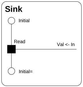
Figure 6: A minimal Sink process in RDT ... 63
Figure 7: A one place Buffer process in RDT ... 64
Figure 8: An instance of the Buffer process named Buff1 ... 65
Figure 9: A Model diagram showing two connections... 67
Figure 10: The Barber process in RDT ... 69
Figure 11: The Customer process in RDT... 70
Figure 12: A Barbershop model with two Barbers and two Customers ... 71
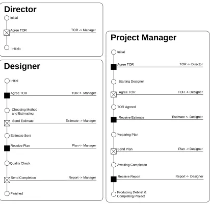
Figure 13: The processes of the Project Management model... 74
Figure 14: The completed model diagram for the Project Management model .... 75
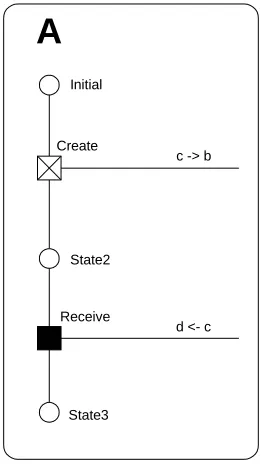
Figure 15: Process A... 90
Figure 16: Process X... 91
Figure 17: Model M1... 91
Figure 18: Process Proc1 ... 104
Figure 19: The “Source” process in RDT... 106
Figure 20: The "Sink" process in RDT... 106
Figure 21: Source and Sink connected directly ... 107
Figure 22: The "Buffer" process in RDT... 107
Figure 23: A model with two buffers inserted between the Source and the Sink 108 Figure 24: Table showing number of states and transitions reported by SPIN for the simple model according to the length of the channel ... 108
Figure 25: Table showing number of states and transitions reported by SPIN for the example using buffer processes and zero length channels ... 109
Figure 26: FSP code for a simple interpretation of RDT model ... 111
Figure 27: LTSA generated diagrams of simple interpretation of model... 111
Figure 29: State and transition counts for simple LTSA model ... 112
Figure 30: FSP code for the revised model ... 113
Figure 31: Diagrams of revised buffer and source processes ... 113
Figure 32: State and transition counts for revised LTSA model ... 114
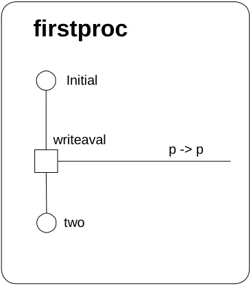
Figure 33: A simple process ... 116
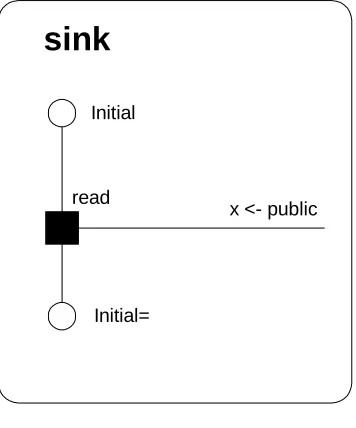
Figure 34: A simple "sink" process ... 117
Figure 35: A simple model showing one instance each of firstproc and sink with a single connection between them... 117
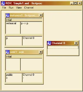
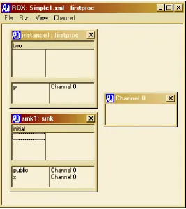
Figure 36: The Simple model immediately after loading into the RDX execution tool ... 119
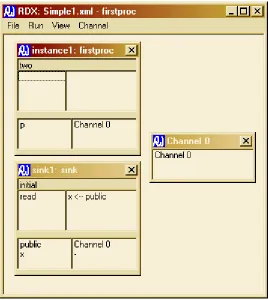
Figure 37: The simple model after the instance of "firstproc" carried out its "write" event showing the value in the channel ... 120
Figure 38: The simple model after the sink process has carried out its read event ... 121
Figure 39: The XML generated by the RDT tool for the simple model... 121
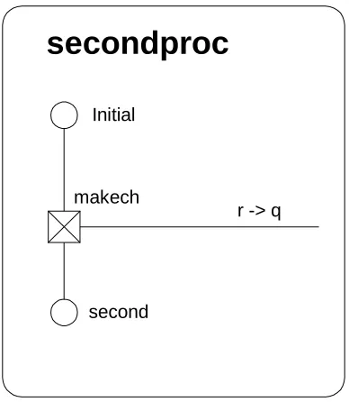
Figure 40: A simple process which creates a channel ... 122
Figure 41: The example model with two instances of "secondproc" added and connection to "sink,public"... 123
Figure 42: The second model loaded into RDX ... 124
Figure 43: The second model after a create event has occurred, but before the corresponding “read” event. ... 125
Figure 44: The second model after the "read" type event has occurred ... 126
Figure 45: The first version of the platform process ... 132
Figure 46: Model view of the first version of MQDefence ... 134
Figure 47: The first MQDefence model during execution ... 135
Figure 48: The Bank process ... 137
Figure 49: The client process... 138
Figure 50: The clearing process... 138
Figure 51: The WebATM model ... 139
Figure 52: "flowgraph" of the car phone application ... 144
Figure 53: The Car process... 146
Figure 55: The BaseI process ... 148
Figure 56: The Centre process... 150
Figure 57: The System model... 151
Figure 58: SPIN generated "never" claim ... 152
Figure 59: The new event dialogue box showing the user selecting a channel from those available ... 195
Figure 60: A typical process diagram... 196
Figure 61: An example "model" diagram... 197
Figure 62: A model during execution... 198
Chapter 1 Overview
As computer and other systems continue to become larger and more complex we
need to find methods which enable us to manage this complexity. In most theatres
where complexity is an issue, a winning technique has been to break the problem
into pieces and then create the required solution by combining a collection of
these pieces. Electronic and computer hardware is an area where this type of
ap-proach has been spectacularly successful. The size of the pieces is a balance.
Smaller pieces are easier to understand and handle, but require greater effort to
assemble into a useful whole.
This technique has been deployed very successfully in many areas and we are
see-ing its adoption in software development as the need arises to manage the
com-plexity of systems more effectively. However, because computer systems inhabit
a world which is devoid of physical laws, they are not subject to the constraints on
variety and complexity which apply to most other systems. As a consequence,
making software systems from collections of components is proving to be more
difficult than in other disciplines.
1.1 Why build executable models?
There are two issues which need to be addressed where a software system is to be
constructed from a collection of components. First there has to be a way to
con-nect the components together. Then we have to get them to do what we want.
The matter of making pieces of software which will fit together has been the
sub-ject of considerable effort and systems and schemes exist which address these
is-sues (COM, EJB, RMI, MSMQ…) [Object Management Group, Sun
Microsys-tems, JavaSoft 1996, Allen and Garlan 1997, Box 1998, Gray, Hotchkiss et al.
1998, Sessions 1998, Thomas 1998, Platt 1999, Microsoft 2001]. Typically, these
arrangements work by managing and controlling the interfaces between
compo-nents (as well as providing some underlying support). Examples of analogous
do-mestic wiring. By forcing components to conform to rules about how they
inter-act with the outside world, these systems ensure that components do not damage
each other when they are connected and perform interactions which each should
understand. To a large extent, this problem may be addressed by managing
ponent interfaces and ensuring that components are only connected through
com-patible interfaces. We can see this type of consideration being applied in the
physical world, in things like the standardised plugs and sockets we use for
do-mestic electricity installations and other applications.
The other problem is more subtle and difficult. We need to ensure that the
assem-bled system does what is required [Gravell and Henderson 1996, Hoare 1996].
Outside of software, this part of the problem of building from components is often
much simpler than matters concerned with a physical interface. For example, the
interface between a domestic appliance and the electricity supply actually only
does one simple action (supplying power) so all that matters is that the connection
is made between compatible interfaces. Although the details are more
compli-cated, the "meaning" of the connection between devices made using a PCI bus is
usually obvious too.
Unfortunately, where the components are pieces of software, it is not the case that
collecting together all the parts we need to solve our problem and connecting them
together respecting the rules associated with their interfaces in a system will
en-sure that the resultant system will do what we want or anything at all [Garlan,
Al-len et al. 1995]. Put another way; just because the interfaces between two
compo-nents permit them to be connected is no assurance that they will interact properly
or even that making the connection makes any sense at all. A good example of
this is from the physical world is a power extension lead. The plug on one end of
the lead is a perfect fit into the socket on the other end, but does fitting them
to-gether make any sense? Probably not.
One approach to solving this problem is to enhance a component's interfaces with
shortcomings: even for small components decorating interfaces in this way is an
enormous task and would prevent the component from being used for a purpose
which was not envisaged when it was designed. And yet, one of the benefits
which can accrue when systems are built using component technologies is the
in-novative use of components (as part of the solution to a problem which was not
envisaged when the component was designed). Taking the example of the power
extension lead again, if we are not interested in supplying power and just want
keep the loose ends tidy, then plugging the two ends together might well be the
thing to do even though it makes no sense in the context for which the article and
its “interfaces” at either end were originally designed.
The real solution to this problem is to reason about and check the behaviour of a
system and the components from which it is built [Hashmi and Bruce 1995,
Magee, Dulay et al. 1995, Ip and Dill 1996, Magee and Kramer 1996, Henderson
1997]. Obviously, the definitive answer to the question, "if we put these
compo-nents together like this, will it work?" can only be obtained by doing it and trying
the completed system. But, if we are to avoid wasting time and effort, we want to
know the answers before we build when the real system is not yet available. So
we have to use something else and this is where models can help [Clarke, Burch et
al. 1991, Clarke, Grumberg et al. 1994, Grumberg and Long 1994, Barjaktarovic,
Chin et al. 1995, Gravell and Henderson 1996, Beizer, Juristo et al. 1997,
Holzmann 1997, Sullivan, Socha et al. 1997, Hartel, Butler et al. 1999, Henderson
and Walters 1999]. These models do not need to replicate the behaviour of the
whole system. All they need to do is to represent the particular aspects of the
be-haviour of the system which we are concerned to check. This means that these
models can abstract away unimportant detail which in turn reduces their
complex-ity and the amount of time and effort required to construct them [Jackson 2002].
However, we do need to be able to analyse these models to ensure both that they
display the required behavioural features and that they are free of undesirable
be-haviours. This analysis could be simple reasoning based on a diagram but, to be
really effective, it needs to be more thorough - and for that we need models which
neces-sary to apply proof techniques to the project [Chin, Faust et al. 1995, Butler 1997],
but often something less rigorous like execution or model checking is more than
acceptable [Coffman, Elphick et al. 1971, Clarke, Grumberg et al. 1994,
Hender-son and Walters 1999].
1.2 Desirable features of a modelling system
Modern software systems are highly complex, typically built from a collection of
components [Hawley 1999]. Some, if not all of these components will be
suffi-ciently complex for a developer to have difficulty understanding their entire
be-haviour fully. Combining them creates a system which is so complex that the
de-veloper needs help with the task of analysing it for correct behaviour. Building
models which are sufficiently formal for them to be executed and subjected to
ex-amination with model checking tools is one technique which can help. And yet,
getting working software developers to build formal models of their systems as
part of their design effort is like getting smokers to give up. In discussion with
either group, they readily agree that the proposed action is a good idea and that
they would benefit from doing it but they don’t act.
The reason why developers are so apparently reluctant to add (formal) modelling
techniques to their design activities is not easy to identify. However, most
exist-ing modellexist-ing systems are dauntexist-ing for the novice to use and this is certainly a
factor.
The problems seem to stem from three areas:
ÿ Most model checking tools require the model to be constructed by writing a
form of code which is specialised to the tool. This means the potential
model-ler needs to learn what amounts to a new programming language syntax and
semantics before they can start to use the tool.
ÿ The features and style of formal modelling systems appear to be motivated by
the creators’ desire to maximise the expressiveness or elegance of their
ÿ Novice modellers have difficulty interpreting the meaning of textual descrip-tions of systems and applying this to their existing understanding of a system.
The success and popularity of UML would appear to support the assertion that
this barrier is lowered considerably when the models are presented as
dia-grams rather than text.
For a modelling system to appeal to the broader community of software
develop-ers, it should have the following features:
ÿ An interface which permits the novice user to build “basic” models quickly
and easily without a significant “up-front” investment of time and effort
learn-ing a new programmlearn-ing language
ÿ Since the medium is so appealing to experts and novices alike, it should be
able to present its models in a diagrammatic form.
ÿ It should have an approach to model construction which has an obvious
sym-pathy with that which will be used in the implementation of the system to be
modelled.
ÿ It should permit the modeller to proceed from constructing their model to
per-forming an analysis of it smoothly, at least for some elementary analysis.
There can be no doubt that formal methods have a reputation for being hard to
use. If we are to see them break out of specialised applications into widespread
use, this perception needs to be addressed and dispelled. Unfortunately for the
“mainstream” software developer, this reputation is probably justified for the
more mature formal methods and their tool support. A new user approaching one
of these methods and its support tools for the first time will have to invest a
sig-nificant amount of time and effort getting to grips with the concepts which
under-lie the operation of the tool. Only after this has been completed can they begin to
understand how using the technique might fit into their design and development
process and what benefits it can bring. Usually they will also have to learn the
syntax of the model input language too. This “up-front” investment in time and
possi-bilities. This investment in initial familiarisation may be reasonable and necessary
if the full benefits of these tools are to be realised. However, developers don’t
always need all of this power and they would be more easily tempted to
investi-gate formal methods if some of this initial effort could be avoided, even if this
re-duced the scope and variety of the analysis which could be applied.
Related to the issue of the high entry cost of using formal methods is the appeal of
pictorial representations of models and processes to potential users. Potential
model builders seem to find a graphical representation of their model which is
generated by the support tool considerably assists them in satisfying themselves
that their code accurately describes the system they wish to examine. Also, where
features of a model have to be described to people outside the mainstream of the
system development activity (such as clients who are unlikely to be familiar with
the technical details of the development of their product), this task is greatly eased
if the model can be presented as a diagram instead of text.
Another difficulty for the inexperienced user of formal modelling systems is to
understand how the communications paradigm of the modelling system maps onto
the inter-process communications which is to be used in the implementation of the
system. Whilst component systems broadly based around procedure calls
con-tinue to be popular, there is a noticeable move away from these synchronous
mechanisms towards asynchronous systems such as message passing middleware
products [Sun Microsystems, Dickman 1998, IBM 2001, Microsoft 2001] and
web based products ["Universal Description Discovery and Integration (UDDI)),
Technical White Paper" 2000, Christensen, Curbera et al. 2000, Microsoft 2000].
The potential difficulty which this generates for developers new to formal model
building is that they don’t see the relationship between the event sharing
commu-nications paradigm preferred by the majority of formal modelling languages and
their own, channel based, understanding of communications within their system
implementations. The shared event communications paradigm feels unnatural to
these people when they encounter it for the first time. It is not that the realisation
communica-tions (for synchronous models), is particularly difficult. Instead it is that, for
many, it is not immediately obvious and adds a further conceptual burden for the
developer building their first few models. Where communication in the
imple-mentation is asynchronous, the situation is more difficult. If it is important for the
model to match the proposed implementation by using asynchronous
communica-tion, this can be achieved easily by the expert. All that is required is for
appropri-ate buffer processes to be inserted between communicating parties as required.
However, with these addition processes included (aside from providing extra
op-portunities for errors to creep in), the model looks less like the implementation
adding to the difficulty of understanding the mapping from the model to the
im-plementation.
The modelling language described in this document attempts to address these
is-sues, though to enjoy the advantages of the language fully, the user needs to work
the language together with suitable support tools. Together with the support tools,
the language permits the creation, execution and limited further analysis of models
without the need for writing code. These models are presented as diagrams which
are designed to be understandable even by observers with minimal knowledge.
In addition to supporting the creation, modification and interactive execution of
models, the example support tools described also provide the modeller with easy
access to checks on their work for features such as deadlock, unreachable code
and unsatisfactory end states by providing an automated translation of models into
the input language of an industry standard model checking tool. A modeller may
apply the more advanced features of the model checker to perform further analysis
of their model including discerning if the model satisfies arbitrary properties
(de-fined by the modeller) using the automatically generated code as a starting point
for this further investigation. However, even if they do not pursue analysis of the
model, building it will have been worthwhile if it helps the modeller/developer to
formulate a system design which is free from deadlocks and unreachable code
[Kaveh and Emmerich 2001]. The motivation for the language is that building
even if the extent of the analysis is strictly limited and seeing the benefits the
ap-plication of a lightweight version of this type of technique might tempt developers
Chapter 2 History and background
2.1 Background
There continues to be some debate about exactly when the computer was invented
with competing claims from at least two machines, but regardless of the reality, it
is not much more than fifty years since the first machine was built. In that time,
computer hardware has progressed at a breathtaking rate. Computers today are so
reasonably priced that they have become a commodity item which almost anyone
can afford whilst at the same time offering features and performance which would
have been unthinkable even just a few years ago. It is a testament to the success
of our hardware engineers that we now have machines small enough to carry in a
pocket and have many times the capability of a machine which would have
occu-pied a large room in the 1960’s. However, although there can be no doubt that the
software we use today is better than what we have been accustomed to in the past,
it would be hard to claim that software has progressed as fast as the hardware on
which it runs. For example, five years ago a 200Mhz computer was considered to
be a high specification machine. Today the norm is in excess of 2Ghz and
200Mhz machines are being discarded as too slow to be useful. Yet, whilst there
have been improvements, the software most of us use on these machines is not
noticeably different.
There is another major difference between the development of hardware and
soft-ware: reliability. We are used to the idea that hardware works exactly as it should
and we expect it to run for months if not years without problems. With the
pre-sent rate of advancement in hardware, this means that much hardware is discarded
as being obsolete long before it develops any faults. At the same time we accept
that software will contain errors (bugs). This disparity in our tolerance of errors is
well illustrated by the public reaction to the discovery of a minor problem in the
floating-point calculations of early Intel Pentium processors [Edelman 1997].
was headline news. Most owners demanded upgraded replacements regardless of
whether the problem was likely ever to affect them. At the same time, bugs were
being routinely discovered and reported by users of all sorts of software – often
the users just found ways to work around them and didn’t even bother to report
them to the developers.
This apparent disparity in the performance of software and hardware systems may
be more apparent than real because, although they are impressively large, there is
not the same enormous variety in the function and behaviour of hardware systems
as there is in software systems. With few exceptions, modern computers are
gen-eral purpose machines built according to the “von Neuman architecture” [Aspray
1991]. The adoption of the general purpose computer was made possible by the
insights of Turing [Turing 1936] and Church [Church 1936] who (independently)
demonstrated that a general purpose computer was able to perform any task which
is possible for any computer. This adoption of the general purpose computer has
assisted the hardware engineers by enabling them to concentrate their efforts onto
a single class of machine.
Hardware engineers also have other advantages over those building software such
as the fact that, at least to some extent, the software engineers have to wait for the
hardware to be built before they can start their work and typically hardware
engi-neers do not have to face changing demands from the ultimate end users.
Cer-tainly it appears that, so far, the hardware engineers have been better able to
han-dle the enormous complexity of modern computer systems than their counterparts
in software engineering.
There are many factors which make the task of building large software systems
difficult. These include relative immaturity of software engineering and the way
that the size and complexity of the systems seems to cause us trouble at many
lev-els. One feature which sets software systems apart from most other types of
sys-tem is the environment in which they operate. They live in a “virtual world”
to construct systems in software which would not be possible in hardware.
How-ever the price we pay for this lack of constraints is increased complexity. Even
specifying how we expect systems should behave seems to be problematic.
Today’s software systems can be very large indeed. Systems which are compiled
from millions of lines of source code are by no means exceptional. With software
systems this big, it is impossible to perform exhaustive testing on them and the
best we can hope to achieve in testing is to check the bulk of the most likely
exe-cution patterns. Even this is fraught as there is no simple way to ascertain the
en-vironment in which a piece of software will be used. Consequently the actual
pat-tern of use may differ significantly from that expected during development. It is
clear that we cannot hope to build and test (or otherwise evaluate) such systems in
a single unit.
If we look at the success of the hardware developers, we see that one of the key
features of their technique for building big systems is construct useful pieces and
then use these components to build progressively larger components until they
have their complete system. It seems reasonable to expect that building software
systems from components should bring similar benefits. In some senses, we do
use components in software systems extensively already. For example, a desktop
system comprising an operating system plus several software applications could
be considered to be built from components but often only one of these programs is
executing at any moment and the interactions between them are mostly limited to
simple, well defined interactions between the operating system and one of the
ap-plications. We are beginning to see more components being used in the
construc-tion of software systems [Szyperski 1998] but this is a style of development which
is not yet as widespread as in hardware.
Despite their advantages, components bring problems too: how do we put them
together? How do we ensure they do what we expect and want? Much of the
dif-ficulty of the first of these questions arises from the “virtual” nature of the world
recent years. Amongst other things this has led to the creation of systems and
schemes which address these issues. These include network communication
pro-tocols (TCP/IP), and message formatting standards (HTML, XML) as well as
component frameworks (COM, CORBA & others), message passing middlewares
(MSMQ, WebShpereMQ). These frameworks address the issues related to how to
put components together. They are very good indeed and it is tempting to suggest
that in principle, if not in practice this problem has been solved. It is easily
possi-ble to create a re-useapossi-ble software component which interacts with other
compo-nents by making appropriate use of these frameworks. They could be considered
as analogous to hardware standards like PCI or USB. However, these frameworks
deal almost exclusively with matters related to how to connect components
to-gether: they attempt to guarantee that components are able to communicate
with-out destroying one another in the process. In some form or another, they are
con-cerned with “interface management”: the form communications should take, the
type and order of parameters in procedure calls, the type of response to expect.
They do not address issues related to whether, having been connected, the
compo-nents actually will interact or what the effects of that interaction might be.
Often, when making physical connections in hardware this is not a problem.
Compared with the equivalent situation in software, the purpose of the connection
between components is often simple and obvious so that difficulties don’t arise.
For example the interface between a domestic appliance and the electricity supply
only does one simple action (supplying power) so that all that matters is that the
connection is made via compatible interfaces (shape of connector, voltage, etc.).
Understanding the “meaning” of the connection and ensuring that the appliance
and the supply behave appropriately is not an issue. This applies to a greater or
lesser extent in most hardware systems. For example, although the details are
more complex, the “meaning” of the connection between devices made using a
PCI bus is usually obvious.
The question of what the behaviour of a collection of connected software
com-ponents is much more diverse. It seems reasonable to suppose that maturing
stan-dards and frameworks will help with some of this complexity in the same way that
they have in hardware, but the problem needs to be addressed if we are to gain the
real benefits of building software systems from pieces (components).
One approach is to press interface technology which has been so successful in
the area of providing the connection infrastructure into service in this area too.
This might be achieved by enhancing the definitions of the interfaces of a
compo-nent with additional elements which attend to the behavioural aspects of the
inter-actions offered through the interface as well as the more practical matters such as
parameter and return values and types. This “decoration” of a component’s
inter-faces could be an enormous task as it would be necessary to encode into it every
possible behavioural pattern into which the component was prepared to take part.
A simple example might be for a component to insist that another perform some
form of registration and initialisation before permitting access to other functions.
Whilst encoding all of these requirements into the interfaces of components is a
huge task and brings some benefits, it would certainly bring with it one very
seri-ous drawback: by preventing unforeseen use of components with restrictions in
their interfaces we would prevent innovative use of components and stifle
creativ-ity in their use. This is much more of a problem in the world of software than in
other areas where components are in widespread use because of the variety and
complexity of the interactions which occur between software components. This
approach is being seriously pursued by some researchers.
An alternative which is advocated in this work is to accept the limitations of the
interface model used in the component frameworks and adopt a different approach
to addressing behavioural issues, modelling. The task of connecting the
compo-nents of a system built from a collection of parts is divided into two. Matters
re-lating to the actual connection of components, the “physical” connection, are
han-dled by (the constraints imposed by) some form of middleware. Matters
con-cerned with what the interconnections “mean” and the behaviour of the completed
behaviour is a part of the design process so to make any sense it cannot be
per-formed on the final system which is not yet built.
Modelling (and simulation) is another technique which has enjoyed enormous
success in the world of hardware development. There are mature hardware
de-scription languages and simulation tools with which hardware engineers can build
impressive representations of systems under development [Jebson, Jones et al.
1993, IEEE 1994, Hodgson and Hashmi 1997, Carpenter and Messer 1998,
Hashmi 1998, Hashmi 1998, Siegmund, Muller et al. 1998]. Using these systems,
hardware engineers are able to experiment with and refine their designs much
more rapidly and cheaply than they could hope to do working with prototype
hardware. Modelling and simulation is immediately attractive in hardware
devel-opment as it permits potential designs to be examined and evaluated without the
considerable trouble, time and expense of building a prototype implementation.
In the software development environment, it is tempting to imagine that, since
they are both software, a model of a system and the software product itself are
in-distinguishable. Although this may be true in a conceptual sense, it is still the
case that building and testing a “real” software implementation is more difficult
and consumes more resources than evaluating a model. The reason is that models
of software systems need not address the complexities and subtleties of the
envi-ronment in which the “real” software is expected to operate. Like the concept of
building from components, the idea of evaluating software systems by the analysis
of models is being adopted by software engineers. We now have a number of
highly respected and powerful systems which are used to simulate and evaluate
software systems [Grumberg and Long 1994, Holzmann 1997, "FDR2 User
Man-ual" 2000]. To use these systems, a developer constructs a model which is then
passed over to the system for evaluation. These evaluations can be quite simple,
such as a “brute force” search of the system states for deadlock. They can also
compare a model’s behaviour with some requirement(s) which may be specified
using the same language as that used to define the model, or some other language
specifically selected (or designed) for the purpose. Typically, these systems are
manage their hunger for memory effectively and complete evaluations of systems
with millions of states in reasonable times. Advocates of systems which avoid
this type of analysis by following the interface enhancement route could argue that
the value of the results obtained from a model is dependent on the accuracy of the
abstraction used in its construction, but similar problems accrue from inaccuracies
in the application of behavioural features to component interfaces.
Modelling has other potential benefits: even when the real system is too large for
exhaustive testing, it should be possible to build a representative model which is a
manageable size. Also, because building a model is an exercise which is
under-taken as part of the design phase of a project, results from an evaluation of a
model can be available long before the product is available for testing.
The purpose of these models is to assist in the task of assembling the constituent
parts of a software system into a coherent whole which will satisfy its
require-ments. For some systems, the function of the model may be simply to document
how the various parts of the system are intended to interact and communicate this
to those involved in the development. In this case, a simple diagram such as a
RAD [Ould 1995] or UML [Fowler, Scott et al. 1997] diagram may well suffice.
However, experience tells us that getting these designs right by simple inspection
of a diagrams (or written descriptions) is notoriously difficult and designers need
help if they are to avoid unexpected and undesirable behaviour in their systems.
For this analysis of models of software to be effective as a tool to help developers
understand the behaviour of their systems, it must be thorough and mechanised.
In turn this means that these models must be more precise than a simple diagram.
The models need to be complete and formal enough to permit them to executed
and subjected to mechanised analysis.
However, whilst most would acknowledge the advantages of building models of
systems and subjecting these to some form of analysis, commercial software
their work. The reasons for this are not entirely clear. There can be no doubt that,
despite the considerable effort which has be expended trying to make “formal
methods” in general more appealing to commercial developers, these techniques
are not in widespread use. They seem to have acquired a reputation for being
dif-ficult to use which deters engineers from considering them.
2.2 Essential features of effective modelling systems
As already indicated, if it is to be useful there must be some purpose in mind
when constructing a model of a system and this purpose will dictate the type and
style of the model which is appropriate. Where the objective is no more than to
record (document) features of a system or communicate these features to the
members of a development team, some kind of informal diagram is likely to
suf-fice. However, even for this purpose, a more formal model may be desirable since
the less formality there is to a model, the more opportunity there is for confusion
to arise from alternative interpretations. Where the purpose of the model is to
as-sist in the process of designing the interactions between the various parts of a
sys-tem or to help the designers to satisfy themselves (and others) of the correctness of
their work, the model necessarily has to be more formal. Once this more formal
model has been constructed, it provides a much more precise description of the
way the system is intended to behave than can be achieved in prose. Such a
model can be used to verify or validate the design of the system by showing how
the system is intended to operate and, with the help of analysis tools, either
dem-onstrate that the system design satisfies various requirements or that the system is
free from undesirable behaviours.
However, if we are to persuade commercial software developers to build more
formal models, we need to supply them with modelling tools and techniques
which they find acceptable. For the most part, it appears that potential users of
formal modelling systems are not concerned about power or expressiveness.
In-stead they are overwhelmed by the awesome power of the systems which they
perceive as having been developed with comprehensive applicability or analytical
systems are to be more widely applied, they need to appear more approachable.
Potential model builders need to feel that it is feasible for them to construct
mod-est models without a great initial invmod-estment of time and intellectual effort and
that the result will be a model which is both sufficiently accessible that they can
discuss it with fellow developers and sufficiently formal that analysis of it can
produce useful results about the behaviour of the system described.
2.3 Characteristics of modelling systems
2.3.1 Formal-informal
A measure of how precise a model is in its description of a system. A reasonable
test of whether a modelling language could be described as formal would be to
consider a modelling language to be formal if it contains enough detail for a
com-plete model to be executed. According to this interpretation of formality, a model
constructed using RolEnact is formal whilst one described by a RAD or a UML
interaction diagram is unlikely to be. For developers to be able to extract the
greatest benefits of modelling, they do need to construct models which are
suffi-ciently precise to be executable.
2.3.2 Graphical/textual
Despite the clear preference of most people for a graphical interface, writing some
form of text (code) is the dominant method by which the modeller describes their
model. Some are then able to convert this description into a diagrammatic
repre-sentation [Henderson 1999, Magee and Kramer 1999, Henderson and Walters
2001] as a static description of the model and/or during its execution (or
anima-tion).
2.3.3 Communications paradigm
The essential feature which underlies all of the modelling techniques described
here is that they describe systems which are built from a collection of parts which
communicate, though they differ in the way that these processes communicate.
channel of some form or by taking part in the some kind of shared action and
whether this communication takes place between just a pair of processes (“point to
point”) or between all processes interested in the event (“broadcast”). In addition,
communication can be “synchronous” or “asynchronous”.
Shared events:
In a modelling language which uses this communications paradigm, where an
event in one process has the same name as an event in another process, these
events must take place at the same time. Normally a process which is ready to
perform a shared event is forced to wait until the other process(es) which are
go-ing to share the event is (are) ready to perform the event. The event is then
per-mitted to occur, and when it does all of the processes which share the event
change state simultaneously.
This communications paradigm is both powerful and permits the construction of
most elegant process algebras, but novice users seem to find it difficult to use. It
appears that they prefer to address communication between processes explicitly
rather than have it occur as the implicit consequence of re-using an event name
even if this means losing some of the elegance of the algebra. Some systems
par-tially address this issue by permitting the modeller some control over the scope in
which events are identified. Unfortunately, rather than helping, this seems to
serve to further confuse the novice. This style of communication is invariably
synchronous – all of the processes which take part in a particular communication
are required to do so at the same instant.
Channels:
A channel is an explicit connection between two or more processes in a model.
Where this paradigm is used, it is usual for the modeller to be required to both
ar-range for communicating processes to know (or be connected to) the channel to be
used and also to cause the communication to occur explicitly. This scheme of
communications seems to appeal to the novice modeller as matching the way they
proc-ess will perform some kind of “send” operation to a channel and another will
per-form a complementary “receive” action on the same channel. This style of
com-munication can be synchronous with all parties to a comcom-munication performing
their actions at the same instant or channels may be able to store communications
enabling sending processes to perform their part of a communication (place values
in a channel) before the receiving process(es) is ready. This further enhances the
appeal of channel based communication for the novice model builder who will be
familiar with buffered communications in other theatres.
Synchronous/Asynchronous communication:
Many modelling languages and systems limit the modeller to constructing models
which use synchronous communication only and this is seen by the inexperienced
as a limitation of these systems. In fact, it is not. Although synchronous and
asynchronous communications behaviours are very different, it is perfectly
feasi-ble to implement either using the other: Buffer processes interposed between
communicating processes is all that is needed to create asynchronous behaviour in
a synchronous systems. A scheme of acknowledgements for messages induces
synchronous behaviour onto an asynchronous system. It is a matter of debate
which of these schemes is better although it would appear that using synchronous
communications leads to more elegant process algebras.
Point to point/Broadcast
The question of which processes take part in a particular communication is
an-other characteristic which differentiates various modelling techniques. With a
“point to point” communications paradigm, exactly two processes are involved in
each communication: typically one sender and one receiver regardless of how
many processes may be available to take part in it. With the “broadcast”
para-digm, the number of processes which take part in a communication is not
re-stricted to two. Instead it may be that any processes presently able to take part in
the communication will do so or it may be mandated that all processes which are
The natural choice for modelling methods which use (synchronised)
communica-tions via shared events seems to be “broadcast” so that when the shared event
oc-curs, it occurs in every process throughout the entire model in which it appears.
Conversely, it would appear that the natural choice for a language which uses
channel based communications is for communication to take place “point to
point”. This rests easily with the notion of one process placing a value into a
channel which another is able to retrieve, possibly later.
As with the synchronous/asynchronous question, there is continuing debate about
which of these alternatives is the better.
2.3.4 Objective
For a model to be considered useful or effective, it must be judged against some
kind of objective. This objective will drive the choice of modelling method to be
used in its construction. For example, something like Promela code is what is
re-quired if the model is to be checked for deadlock using a model checking tool, but
would be highly unsuitable to present an outline of the system to a non-technical
audience where a UML sequence diagram might be ideal.
The following is a representative selection of tools and languages and techniques
available for building and analysing models of systems:
2.4 Existing systems
We already have a large collection of modelling tools, languages and techniques.
Some of these attempt to provide a comprehensive solution to every modelling
requirement whilst others are tailored for a particular purpose. These languages
can be classified in a number of ways:
2.4.1 UML
The Unified Modelling Language is representative of many diagram based
model-ling systems and currently is possibly the most popular of them. UML attempts to
pe-riod of years into a single coherent system. In doing so, arguably there is some
duplication in UML where more than one type of diagram portrays essentially the
same information. At the same time the language permits latitude in the way that
its various diagrams are drawn and interpreted. Most relevant to the type of
mod-elling under consideration here are activity and sequence diagrams. These
dia-grams are used to describe how parts of a system interact. Not only are they are
easy to understand and construct, they provide an effective mechanism for
com-municating these ideas to a non-expert audience. A strength of UML is that it is
becoming widely accepted in industry and there are heavy weight commercial
packages available to support its users. However, in general, models created
us-ing UML do not lend themselves to formal analysis. This is not a criticism. The
degree of freedom which this gives to the modeller using UML is one of the
strengths of the language. This work could have used a sub-set of either activity
or sequence diagrams, but it was felt inappropriate to make changes to such well
known notations. [Fowler, Scott et al. 1997]
2.4.2 Rapide/Darwin/Wright
Rapide, Darwin and Wright [Luckham, Kenney et al. 1995, Luckham and Vera
1995, Magee and Kramer 1996] are representative of the approach to the problems
of building software systems from components which attempt to incorporate
be-havioural issues into component interfaces.
2.4.3 Process Algebras and Model checking
In a sense, these techniques occupy the middle ground between informal system
construction and rigorous formal development [Ip and Dill 1996, Holzmann 1997,
Sullivan, Socha et al. 1997]. They do not provide “proof” of the correctness of a
system in manner of “traditional” formal development where a system is
devel-oped from a specification (which is proven to have the required properties) by
successive steps, each of which is proven to preserve the required features of the
initial specification (and any other requirements arising from previous steps of the
development). Instead, they provide a language with which a representative
sub-jected to analysis, hence the name of the technique. In principle, if not in actual
practice, model checking tools operate by performing an exhaustive search of all
of the states of a model. This search is directed at establishing some particular
property of the model. Typically, model checking software permits the modeller
to input the property to be checked in either the same language as is used to
de-scribe the model or another language tailored for this particular purpose. In
addi-tion, or as an alternative, the modeller may be offered the opportunity to check a
model for one of a number of standard properties, such as the model having no
unreachable code or being free from deadlock. Generally, where a model check
discovers a problem, the system will give the modeller a trace showing how the
model is able to reach an unsatisfactory state.
Model checking software is already sophisticated and it is feasible to examine
models with many millions of states in reasonable periods of time. Further
devel-opment of these systems and continuing advances in hardware will enable them to
handle even larger systems in the future. However, despite the great power of
these systems, there is no realistic hope of them ever being able to handle the full
detail of complete commercial systems.
2.4.4 CSP/FDR
Communicating Sequential Processes (CSP) [Hoare 1985] is a formal language
for constructing models of interacting systems. It is a highly respected language
with a good pedigree. Communication between processes in CSP is achieved by
shared events. Each event which can occur in a model has a name. In its standard
form, when an event occurs in CSP, it happens in all of the processes in which that
event name appears. The event can only occur when it can happen in all of the
processes containing the event. Where it is desired that an event is shared
be-tween a limited number processes, this is achieved by means of a system of
label-ling events (and processes). This style of communication is appropriate for some
A strength of CSP is that there is commercial strength tool support for the
lan-guage such as the model checker, FDR. FDR is a fully featured and powerful
model checking tool able to analyse substantial models written in CSP.
2.4.5 FSP/LTSA
Finite State Processes (FSP) [Magee and Kramer 1999] is a smaller modelling
language based on CSP. It lacks some of the power of CSP, being carefully
crafted to ensure that its models are finite. It is interesting in this context as
evi-dently part of the reason for the constraints incorporated into FSP is to permit it to
be used as the input language to the modelling tool, LTSA. LTSA is an attractive
tool. It has easy to use features and will draw diagrams of FSP models in the form
of Labelled Transition Systems. It is also able to check FSP models for a variety
of fundamental properties. However, in common with CSP/FDR, model input
into LTSA still requires the modeller to write code. Consequently, in addition to
the concepts of FSP, the modeller needs to learn the syntax of the language.
2.4.6 ALLOY
Alloy is a modest, declarative modelling language developed principally by
Daniel Jackson. The philosophy of Alloy has a number of appealing features. In
particular, the developers talk about what they describe as “micro-modelling”.
They assert that, regardless of the size of the target system, the analysis of models
of parts or aspects of they system can provide useful insight even when these
models are constructed with just a few lines of code [Jackson 2002].
A further interesting feature of the Alloy modelling language is the mechanism
which is employed by the support tool for the analysis of the models. Instead of
attempting to provide comprehensive support for the Alloy language and the
analysis of models constructed using the language in the support tool, the
devel-opers have concentrated on the interface to the user and the features which set
Al-loy apart from other systems. For analysis, models are recast (mechanically by
(commercial) third party “solver”. The outcome of the analysis by the “solver” is
then re-cast into an appropriate form and presented to the user.
2.4.7 Pi-Calculus
The pi-calculus [Milner 1993, Turner 1995] is a process algebra with a formidable
pedigree. Its basic concepts are few in number and powerful. Like CSP,
pi-calculus inter-processes communicate synchronously but in contrast
communi-cation takes place “point to point” through channels. The pi-calculus builds on the
earlier work in “A Calculus of Communicating Systems” (CCS) [Milner 1989].
Despite its pedigree, there is no well known heavy weight implementation of an
execution tool or model checker based on the pi-calculus (like FDR for CSP).
The major concept of the pi-calculus is of a “name”. Names are used to identify
processes, channels and the values which are passed around between processes
which contributes to the elegance of the calculus and enables some of its more
powerful features. For example, since a channel is just a “name” and “names” are
used for the values passed between processes in communication, processes are
able to pass channels around (through channels) which permits a rearrangement of
the interconnections between the constituent processes of a pi-calculus model
dur-ing execution. This facility for dynamic re-configuration sets the pi-calculus apart
from most other process algebras.
The essential features of pi-calculus are described in Chapter 6.
2.4.8 SPIN
SPIN is a highly featured, highly respected model checker which is both
success-ful and popular. In common other model checking systems, SPIN models are
built by writing code in a language devised for the purpose. The model input
lan-guage of SPIN is “Promela” which has a syntax reminiscent of the popular
SPIN has a graphical “front end” (XSPIN) which transforms the appearance of the
analysis of a model, but the modeller still has to write code to construct their
model for which they need to understand the Promela language.
SPIN and Promela are described further in Chapter 7
2.4.9 RADs
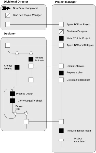
A Role Activity Diagram (RAD) is a style of diagram developed by Martin Ould.
These diagrams and their application to business process modelling are described
extensively in his book [Ould 1995]. The particularly attractive feature of RADs
is the clear uncomplicated way that they describe the behaviour of a process. In
Ould’s work he is concerned to describe business processes and change, but the
technique is sufficiently general to be applied to any form of process. A complete
RAD shows a collection of processes and how they interact. Each process is
con-tained within its own box and interacts with other processes by sharing events.
Each process has a starting point at the top of its box and progresses by taking part
in events which take it into new states. The state of a process may be named.
Named states are shown as circles labelled with the name of the state. Where a
process returns to a previously visited state, this may be shown by a loop back to
that state, but the rules governing the drawing of a RAD also permit a state to
ap-pear in the diagram in more than one location permitting the model builder to
show looping behaviour without breaking the convention that the flow of control
in a process moves down the page (and some freedom in the arrangement of the
New Prioject Approved
Start new Project Manager
Agree TOR for Project
Start new Designer
Write TOR for Project
Agree TOR and Delegate
Prepare Estimate
Obtain Estimate Choose
Method
Produce Design
Carry out quality check
Design OK?
n y
Prepare a plan
Give plan to Designer
Produce debrief report
Project completed
Divisional Director Project Manager
[image:39.612.115.492.42.646.2]Designer
Within a RAD, there are several classes of event. The simplest is carried out by a
process in isolation (and is shown as a black square). Others involve some form
of communication between processes (shown as a white square). Communication
within RADs is by means of shared events. However, unlike most modelling
techniques which use this paradigm, shared events in a RAD are highly visible to
the modeller as they are shown by a horizontal line connecting the events
in-volved. Most shared events involve two Roles, but the notation admits the
possi-bility that three or more may share in an event. There is no requirement to
indi-cate which of a number of Roles sharing an event is responsible for initiating the
event, but this may be shown by the box for the event in the “driving” Role being
shaded.
A RAD process also has access to a special type of event which causes another
process to be brought into existence. Such an event is distinguished by having a
cross in its box. The type of Role which is created in the event is indicated in a
label attached to the event.
Within the RAD notation, in addition to the various types of event, there are
con-structs which permit the description of choice and parallel execution within a
process (or Role). In addition to the features described above, the full RAD
nota-tion has further features which permit the user, amongst other things, to add
de-scriptions to states (in addition to naming them), external events which affect
Roles and show partial descriptions of Roles.
2.4.10 RolEnact
RolEnact [Phalp, Henderson et al. 1998, Henderson 1999, Henderson and Walters
1999, Henderson and Walters 2001] was developed by Peter Henderson. It has a
special place in this work and it is described further in Chapter 3
Like RADs and in contrast with the other techniques described above, the intitial
modelling. This objective meant that it was anticipated that the RolEnact models
would be built by business people who, although experts in their own fields,
would have limited knowledge and tolerance of computer programming.
Conse-quently, the RolEnact language was kept deliberately small to minimise the
fa-miliarisation required before a new user could see their first models running. This
overriding desire to make the language suitable for use by the “non-expert”
brought with it the need to accept that there would be limitations in the
expres-siveness of the language.
RolEnact succeeded in some respects. It has an attractive execution tool in which
each running instance of a Role has its own window in which is displayed
infor-mation about the Role and the actions it is presently able to perform. This
inter-face seems to be sufficiently straightforward for the non-specialist modeller to
un-derstand what is happening and relate the behaviour of the model to the real
situa-tion being modelled (and a RAD where this is available).
However, although the language of RolEnact was particularly small (especially in
its revised form), this need to write code in order to produce models still seems to
present a barrier to the construction of models by non specialists.
2.5 Conclusion
There already exists a large and varied collection of modelling tools and
tech-niques which might be appropriate for the construction of a model of any kind of
proposed system to be built from a collection of parts. These systems vary from
informal diagramming techniques to hard formal systems with rigorous
mathe-matical underpinnings.
However, whilst most developers would accept an argument which proposed
analysis of models as part of the process of evaluating system designs, few models
are actually built. Regardless of the actual reality, modelling systems and their
To some extent these systems:
• Attempt to offer features (e.g., Expressive power) at the expense of
“useability”
• Provide users with a text (or code) based interface although it is clear that they find this unattractive
• Require potential users to engage in a significant conceptual challenge be-fore they are able to build and use even the simplest of models
• Provide only synchronous inter-process communication (typically using
“shared events”) when the typical enterprise system being constructed
to-day will use a channel based asynchronous communications of some form.
Working developers are already persuaded of the benefits of using formal and
semi-formal methods to assist them in the design and development of today’s
large systems and whilst not all of the problems are solved, existing systems are
more than good enough to be very useful. However, if we are to incite people