warwick.ac.uk/lib-publications
Original citation:
Sprittles, James E. (2017) Kinetic effects in dynamic wetting. Physical Review Letters, 118 (11). 114502.
Permanent WRAP URL:
http://wrap.warwick.ac.uk/85833
Copyright and reuse:
The Warwick Research Archive Portal (WRAP) makes this work of researchers of the University of Warwick available open access under the following conditions.
This article is made available under the Creative Commons Attribution 4.0 International license (CC BY 4.0) and may be reused according to the conditions of the license. For more details see: http://creativecommons.org/licenses/by/4.0/
A note on versions:
The version presented in WRAP is the published version, or, version of record, and may be cited as it appears here.
Kinetic Effects in Dynamic Wetting
James E. Sprittles*
Mathematics Institute, University of Warwick, Coventry CV4 7AL, United Kingdom
(Received 2 August 2016; published 16 March 2017)
The maximum speed at which a liquid can wet a solid is limited by the need to displace gas lubrication films in front of the moving contact line. The characteristic height of these films is often comparable to the mean free path in the gas so that hydrodynamic models do not adequately describe the flow physics. This Letter develops a model which incorporates kinetic effects in the gas, via the Boltzmann equation, and can predict experimentally observed increases in the maximum speed of wetting when (a) the liquid’s viscosity is varied, (b) the ambient gas pressure is reduced, or (c) the meniscus is confined.
DOI:10.1103/PhysRevLett.118.114502
Understanding the physical mechanisms determining the maximum speedUmaxat which a liquid-gas free surface can wet a solid substrate is a fundamental problem with applications to a range of natural and technological phenomena. For example, if drops of rain (or pesticide) spreading across plant leaves exceedUmaxthen a splash is generated, which reduces the retention of liquid[1], while coating processes must operate below Umax in order to avoid product-destroying gas entrainment [2].
Despite the small gas-to-liquid density and viscosity ratios (ρg=ρl≈10−3 and μg=μl≈10−2 for air-water), the importance of gas dynamics has been established both in coating flows and in impact events, for the collisions of solid bodies with liquids[3]and liquid drops with solids. In particular, recent activity in liquid-drop impact has been aimed at understanding the role of gas using novel experimental techniques, see [4] and references therein. While a full characterization of drop splashing remains an open problem, recent experiments in [5] highlight the critical role of gas films during the wetting phase.
The gas dynamics become relevant when thin films are formed that generate lubrication effects, with experimental observations in both coating [6] and drop impact [7]
showing that the height h of these films is in the range
≈1–10μm as Umax is approached [8]. At atmospheric pressurePatm (“atm”will denote atmospheric values), the mean free path in the gaslis≈0.1 μm, so that the Knudsen number Kn¼l=h≈0.01–0.1. Consequently, it has been suggested[6,9]that kinetic effects in the gas should be built into models for moving-contact-line phenomena.
Recent models[6,9]account for kinetic effects by allowing for “slip,” i.e., a jump in the velocity tangential to the boundary, at the gas-liquid and gas-solid interfaces, with a
slip length proportional tol[10]and the usual equations of hydrodynamics remaining in the bulk. These models can qualitatively explain experimental observations in coating
[11]and drop impact [12] that reductions in the ambient gas pressureP can suppress gas entrainment and splashing
[13]: as l¼latmPatm=P increases with reduced P, slip is enhanced and gas is more easily removed from the thin film. Research in kinetic theory has established that these“ first-order” slip models are only accurate for Kn≲0.1. Technically, they can be derived from the Boltzmann equation for small Kn[14]. Physically, they represent the case where the nonhydrodynamic effects, in the so-called Knudsen layer, are confined to a boundary layer of width≈l which is small relative to the channel height (l≪h) so that this additional physics can be incorporated into boundary conditions. These models are on the edge of their appli-cability for dynamic wetting at atmospheric pressure, where Kn≈0.01–0.1, so that when P is reduced they will be outside their limits of validity. This has been confirmed in
[9], where it has been shown that the situation is even more severe, as decreases inPalso lead to reductions inh, so that Kn can easily exceed unity in experimentally realizable conditions.
In this Letter, methods originally developed to predict rarefied lubrication flows in micrelectromechanical sys-tems [15] are used to derive a dynamic wetting model which is valid for all Kn. As demanded by the physics, this model combines kinetic theory in the gas film described by the Boltzmann equation with hydrodynamics in the liquid phase governed by the Navier-Stokes equations.
Flow configuration.—The steady dynamic wetting geometry in Fig.1 allows us to consider both a coating flow, where a solid is continuously driven through a liquid bath whose free surface is flattened by gravity, as well as the steady propagation of a meniscus confined to a micro-channel of width2L. These cases correspond, respectively, to L≫Lσ ¼ ffiffiffiffiffiffiffiffiffiffiffiffiffiffiffiσ=ðρlgÞ
p
and L≪Lσ, where Lσ is the capillary length withσthe liquid-gas surface tension andg the acceleration due to gravity.
The liquid’s flow is described by the steady incompress-ible Navier-Stokes equations. At the liquid-solid interface conditions of impermeability and Navier slip are used which circumvent the moving-contact-line problem, choos-ing a fixed slip length ofls¼10nm which is well within the range of experimentally observed values. At the liquid-gas free surface, the kinematic condition is combined with a balance of stress and capillarity. The contact angle at which the free surface meets the solid is assumed to be a constant
θe. By construction, the simplest possible dynamic wetting model (formulated mathematically in the Supplemental Material [16]) has been chosen to allow us to focus attention on the dynamics of the gas without additional parameters coming into play. Having established the importance of the gas, more complex models for the wetting process, such as dynamic contact angles (reviewed in [25]), can be built on top of this basic model.
As the gas flow is only strong enough to affect the liquid when it is thin, the lubrication equations can be used to describe its dynamics, see [26]. Simulations comparing results from this formulation to full computations of the gas phase confirm the accuracy of this approach (Supplemental Material[16]) and indicate that the gas only influences the liquid through the pressure term in the normal stress boundary condition; one may expect for μg=μl≪1 the gas’s contribution to the tangential stress condition is negligible compared to that of the liquid. Consider then, in the lubrication framework, three different models for the gas phase: (i) No slip: conventional model, with a nonzero slip length (fixed at 10 nm) at the solid boundary only to circumvent the moving-contact-line problem; (ii) Slip: current state-of-the-art model, with slip at the gas-solid and gas-liquid boundaries proportional to l; (iii) Boltzmann: the model developed in this Letter, with the gas phase described by kinetic theory.
Thin-film gas dynamics.—As the process is steady, a pressure-driven Poiseuille flow forms to remove the gas dragged into the contact-line region by a boundary-driven Couette flow, caused by the motion of the solid moving at constant speed U and the liquid at UfsðxÞ tangential to the free surface (Fig. 1). Such arguments are routine in hydrodynamics, and are formalized in the Reynolds equation, but more recently they have been generalized for the Boltzmann equation[15,27]. There, it is possible to identify Poiseuille and Couette flow components, but the Boltzmann equation must be solved to evaluate the respective contributions to the mass flux.
Assuming diffuse reflection of molecules from each boundary, which is a sensible starting point, due to symmetry the mass flux from the Couette flowmCremains the same for all models while the plane Poiseuille flow contributionmP is model dependent,
mC¼1
2ρghðUþUfsÞ; mP¼ ρgh2l
ffiffiffi π
p
μg dp
dxQðKnÞ; ð1Þ
[image:3.612.57.292.48.194.2]whereQðKnÞare the so-called“flow coefficients”[28]that depend on the model used [Fig. 2(a)] and p is the local pressure. For this problem it is reasonable to assume incompressible flow [see Fig. 4(b) for confirmation], although the extension to compressible flow is not difficult, see[29].
FIG. 1. Flow configuration (left) and close-up of the thin-film region (right) showing that (a) the heighthðxÞand speed in the liquidUfsðxÞvary withx, (b) there is a Couette-Poiseuille flow profileugin the gas, and (c) the free surface bends to attain its contact angleθ. At the upper and lower boundaries of the domain, a distance4Lapart, is a stationary solid.
(a)
(b)
FIG. 2. (a) Predictions of the flow coefficients QðKnÞ from Eq.(1). (b) Curves of r, defined in Eq.(2), and demonstration (inset) that the slip model diverges from the Boltzmann solution for larger Kn.
[image:3.612.320.555.408.665.2]Notably, only the Boltzmann equation captures the famous “Knudsen minimum” [Fig. 2(a)] in the mass flux of gas through a channel of fixed h [so that ðρgh2lÞ=ð
ffiffiffi π
p
μgÞ is a constant] which is driven by a constant pressure gradient.
Conservation of mass (mC¼−mP) then gives
− h2
12rμg dp dx¼
UþUfs
2 ; rðKnÞ ¼
ffiffiffi π
p
12KnQðKnÞ; ð2Þ
where it is noted that h, Ufs, and Kn all vary along the film. The form of (2) suggests that an effective viscosity could be defined asμeffg ¼rμg, as considered in [6,11], in order to absorb kinetic corrections into a hydrodynamic framework; this idea has recently been pursued in pioneering drop collision simulations [30]. Notably, at Kn¼0.1, 1, 10 it is found thatμeff
g =μg¼0.6, 0.1, 0.007, showing the rapid drop in resistance as the film height is reduced. Although this gives us a picture of the role that rplays, it can confuse matters, as pointed out in [31], as
μeff
g is problem specific and dependent on the ambient pressure, while μg is not. Therefore, rðKnÞ is retained in the formulation.
For Kn≪1, the Knudsen layer is small relative to the channel height and the results of the Boltzmann equation are equivalent to using the Navier-Stokes equations with Navier slip at the boundary accounting for the nonhydro-dynamic effects. For the slip model r¼ ð1þ6αKnÞ−1, where αl is the slip length andα≈1is a parameter that depends on both the collision model in the Boltzmann equation and the accommodation coefficient of the surface
[31]. For Kn¼0,r¼1[32].
Methods for obtainingrðKnÞ, or more typicallyQðKnÞ, from the Boltzmann equation are reviewed in[28]and often involve simplifications from a Bhatnagar–Gross–Krook (BGK) approximation and/or linearization. Experimental data are well captured by most variants and so here the simplest possible approach of linearized BGK (whereα¼
1.15[33]) is used. To solve this model a variational method proposed in[34]is implemented, which is shown in[28]to be the simplest method for accurately approximating Q (giving results within 2% of the exact Boltzmann solution). This leads to the curves forQandrlabeled Boltzmann in Fig. 2. While the slip model appears satisfactory at first glance of Fig.2(b), the inset shows that the relative error of r from the Boltzmann solution becomes unacceptable for Kn≳0.1.
Simulations.—The problem is solved using a multiscale finite-element framework developed in [35] and first applied to gas entrainment phenomena in [9], where it was benchmarked with a similar code [36]. As there are length scales of nm (ls), μm (l), and mm (Lσ) in the problem, the computational mesh, based on an arbitrary Lagrangian Eulerian description, has to be specially designed to capture all of the physical effects. The main
output from this code is the maximum speed of wetting Umax, past which no steady two-dimensional solutions exist
[9]and gas entrainment is expected to occur. As noted in
[37], predictions of flow transitions are ideal candidates for comparing models for moving-contact-line phenomena, as they are easily observed experimentally, in contrast to measurements of the contact angle.
The extension of this code to allow for a thin-film description of the gas flow is relatively straightforward, and as suggested in[38], and developed in [26], it is assumed thatdx≈ds(Fig.1) in order to circumvent regions where the thin-film approximation is not strictly valid. Benchmark simulations in the Supplemental Material show the scheme is highly accurate [16], giving values for Umax that are indistinguishable from those obtained when solving the full problem in the gas.
Values forrðKnÞobtained from the Boltzmann equation could either be calculated“on the fly,”i.e., when required by the code (a“concurrent”approach), or before the code is run (a“sequential”method). For simplicity, the sequential method is chosen and the Supplemental Material provides the code used to generaterðKnÞ[16].
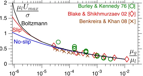
Atmospheric pressure.—Standard dip-coating experi-ments measure the air (latm ¼70nm, μg¼18μPa s) entrainment speed Umax for different liquids on a range of solid substrates. In Fig.3, this data is shown for water-glycerol solutions whereσ¼65mN m−1is approximately constant, so that the effect of varying the liquid’s viscosity (dimensionlesslyμg=μl) can be isolated. Despite no attempt to fit the data (θe ¼90° is fixed), the theoretical predictions are in good agreement with the experiments and support the validity of the approach.
Remarkably, for μg=μl<10−5 kinetic effects become prominent at atmospheric pressure, as the gas film’s height shrinks and becomes comparable to latm. This creates a dependence on μg=μl that diverges from the no-slip model, with the slow logarithmic increase of μlUmax=σ blown away by a rapid power-law-type increase. Interestingly, this is supported by experiments in[39]that for high viscosity liquidsUmax→0.1ms−1, corresponding
10-6 10-5 10-4 10-3 10-2
0 0.5 1 1.5 2
Burley & Kennedy 76 [ ]
Benkreira & Khan 08 [ ]
Blake & Shikhmurzaev 02 [ ]
Slip
No-slip
Boltzmann
[image:4.612.320.558.548.675.2]to μlUmax=σ→ðμg=μlÞ−1, and similar scalings are in [6]. Clearly, further experimental analysis at μg=μl<10−5 is required to properly elucidate the new trends.
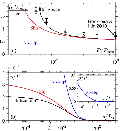
Reduced ambient pressure.—Consider the dip-coating experiments performed in [11] (see their Fig. 9) with silicone oil (viscosity μl¼112mPa s, density ρl¼ 985kg m−3, surface tension σ¼17.9mN m−1, equilib-rium contact angle θe¼19.5°) as the coating liquid and helium as the ambient gas, inside a pressure-controlled chamber. Helium’s mean-free path latm ¼190nm at atmospheric pressurePatm¼105Pa is 3 times larger than that of air, so kinetic effects will be enhanced, while its viscosity is similarμg ¼19μPa s.
In Fig. 4, the computational results are compared to experimental data. The main results are that (a) the no-slip model completely misses the qualitative trend ofUmax as the pressure is reduced, (b) the Boltzmann model diverges from the slip model once the ambient pressure has been reduced by a factor of 10, and (c) the Boltzmann model appears to slightly better describe the experimental data. Such agreement between theory and experiment is remark-ably good, when allowing for the simple dynamic wetting model implemented and the fact there are no parameters to fit. However, the key message is that kinetic effects play a role in moving-contact-line phenomena in experimentally accessible regimes.
Typical profiles in Fig.4(b)show how the model chosen changes the pressure distribution in the film. It is clear that the no-slip model drastically overpredicts the pressure, peaking atp¼0.07P, while the slip model’s prediction is just 4% of this value. The Boltzmann model gives further substantial reductions. Variations in pressure along the film are consistent with gas incompressibility.
Confined menisci.—By considering the effect ofUmaxon flow dimensionL(Supplemental Material[16]), full kinetic effects are also shown to be critical for“microfluidic flow,” which could either be a meniscus confined to a micro-channel or when the bulk flow creates regions of large curvature, as in drop impact.
Physical mechanisms.—In [40], careful simulations identified that entrainment occurs when the capillary forces at the free surface can no longer sustain the pressure gradients required to pump gas away (via a Poiseuille flow) from the contact-line region. Global balances of capillary and viscous forces have also been used in unsteady processes to predict splashing[3,41]and microdrop emis-sion[42], where exceedingUmaxresults in the contact line being left behind the advancing liquid front[43].
Interestingly, computations here and in [40] show that the free-surface shape is relatively insensitive to the gas dynamics. Its shape is determined by the balance of viscous forces in the liquid with capillary forces at the interface. Wettability then enters the model as a boundary condition for the free-surface shape, as does confinement when the channel is sufficiently narrow. Therefore, given this profile, we can compare the pressure buildup in the film for the different models of the gas.
Isolating the Poiseuille flow component, Eq. (1)shows that the pressure gradient required to drive a given mass fluxmPis inversely proportional toQðKnÞ, so that pressure increases will be least for the Boltzmann model, where QðKnÞ is largest [Fig. 2(a)], as confirmed by Fig. 4(b). Physically, the increased Q predicted by the Boltzmann model occurs for Kn>0.1 as nonequilibrium effects not only cause slip at the wall, but also drive a non-Newtonian bulk flow. As expected from Fig.3and4(a), it is the models with the smallest increases in pressure, i.e., the largest QðKnÞ, which predict the largest Umax.
Encouragingly, it appears that the free-surface shape could be calculated independently of the gas phase and used to infer the maximum pressure gradients that the free surface can sustain. This is where the dependencies on the capillary number, wettability and confinement would enter the model. With this informationUmaxcould be calculated from lubrication theory for the gas phase, where kinetic effects would enter. However, as no simple method currently exists for characterising the required free surface profiles, a less computationally intensive model based on these ideas remains an open problem.
Discussion.—Simulations have identified situations where conventional approaches fail to predict Umax due
10-1 100
0 0.5 1 1.5 2
Benkreira & Ikin 2010
(a)
10-4 10-2 100
0 1 2 3 4
10-4 10-2 100 0
0.05 0.1
[image:5.612.60.294.387.642.2](b)
FIG. 4. (a) Maximum speed of wetting, for silicone oil in helium, as ambient pressurePis reduced. (b) Local pressurep relative to its far-field value and normalized by the ambient value P¼0.06Patm, at a contact line speedμlU=σ¼0.5, just before the no-slip model predicts entrainment. The distance along the free surfaces starts in the thin-film region.
to an inadequate description of the flow physics in the gas film. While the slip model captures the qualitative behavior, the Boltzmann equation is required for quantitative pre-dictions and thus deserves further attention. Incorporating this new physics into existing codes is relatively simple and could play a role in a wide range of free-surface flows where gas microfilms appear, such as in the collisions of liquid drops[44], the formation of tip singularities in free surfaces[45], the stability of nanobubbles on solids [46], the impact of projectiles on liquid surfaces [47], and the creation of antibubbles from air films [48]. Furthermore, these findings motivate new directions of research, such as (a) understanding how gas molecules interact with moving liquid-gas free surfaces, from experiments or molecular dynamics simulations, and (b) developing nonlubrication formulations of the gas flow, such as moment method approaches [49].
The author thanks Duncan Lockerby and Alex Patronis for useful discussions and the reviewers for their con-structive criticism. This work was supported by the Leverhulme Trust (Research Project Grant) and the Engineering and Physical Sciences Research Council (EPSRC) (Grant No. EP/N016602/1).
*
[1] V. Bergeron and D. Quéré, Water droplets make an impact, Phys. World14, 27 (2001).
[2] S. J. Weinstein and K. J. Ruschak, Coating flows, Annu. Rev. Fluid Mech.36, 29 (2004).
[3] C. Duez, C. Ybert, C. Clanet, and L. Bocquet, Making a splash with water repellency,Nat. Phys. 3, 180 (2007). [4] C. Josserand and S. T. Thoroddsen, Drop impact on a solid
surface,Annu. Rev. Fluid Mech.48, 365 (2016).
[5] Y. Liu, P. Tan, and L. Xu, Kelvin-Helmholtz instability in an ultrathin air film causes drop splashing on smooth surfaces, Proc. Natl. Acad. Sci. U.S.A.112, 3280 (2015).
[6] A. Marchand, T. S. Chan, J. H. Snoeijer, and B. Andreotti, Air Entrainment by Contact Lines of a Solid Plate Plunged into a Viscous Fluid,Phys. Rev. Lett.108, 204501 (2012). [7] M. M. Driscoll and S. R. Nagel, Ultrafast Interference Imaging of Air in Splashing Dynamics,Phys. Rev. Lett.
107, 154502 (2011).
[8] Orders of magnitude larger than the characteristic scales for roughness of the substrate.
[9] J. E. Sprittles, Air entrainment in dynamic wetting: Knudsen effects and the influence of ambient air,J. Fluid Mech.769, 444 (2015).
[10] The “correction factor”r in Eq. (10) of the Supplemental Material of [6], which accounts for kinetic effects, has precisely the form of a slip model.
[11] H. Benkreira and J. B. Ikin, Dynamic wetting and gas viscosity effects,Chem. Eng. Sci. 65, 1790 (2010). [12] L. Xu, W. W. Zhang, and S. R. Nagel, Drop splashing on a
dry smooth surface,Phys. Rev. Lett.94, 184505 (2005). [13] Impact is more complex as compressibility and kinetic
effects are both expected to play a role[4].
[14] C. Cercignani,Rarefied Gas Dynamics: From Basic Con-cepts to Actual Calculations(Cambridge University Press, Cambridge, England, 2000).
[15] C. Cercignani,Slow Rarefied Flows: Theory and Applica-tion to MEMS(Birkhäuser Verlag, Basel, 2006).
[16] See Supplemental Material at http://link.aps.org/ supplemental/10.1103/PhysRevLett.118.114502, which in-cludes Refs. [17–24], for (a) a full mathematical problem formulation with additional details of the lubrication model developed, (b) benchmark simulations establishing the limits of applicability of the lubrication approach and (c) results for confined menisci.
[17] Y. D. Shikhmurzaev,Capillary Flows with Forming Inter-faces(Chapman & Hall/CRC, Boca Raton, 2007). [18] T. D. Blake and J. M. Haynes, Kinetics of liquid/liquid
displacement,J. Colloid Interface Sci.30, 421 (1969). [19] J. E. Sprittles and Y. D. Shikhmurzaev, Finite element
simulation of dynamic wetting flows as an interface for-mation process,J. Comput. Phys.233, 34 (2013). [20] A. Oron, S. H. Davis, and S. G. Bankoff, Long-scale
evolution of thin films,Rev. Mod. Phys.69, 931 (1997). [21] E. Vandre, M. S. Carvalho, and S. Kumar, Characteristics of
air entrainment during dynamic wetting failure along a planar substrate,J. Fluid Mech.747, 119 (2014).
[22] C. Cercignani and C. D. Pagani, Variational approach to boundary-value problems in kinetic theory,Phys. Fluids9, 1167 (1966).
[23] K. A. Hickey and S. K. Loyalka, Plane Poiseuille flow: Rigid sphere gas,J. Vac. Sci. Technol. A8, 957 (1990). [24] C. Cercignani and A. Danieri, Flow of a rarefied gas
between two parallel plates,J. Appl. Phys.34, 3509 (1963). [25] T. D. Blake, The physics of moving wetting lines,J. Colloid
Interface Sci.299, 1 (2006).
[26] E. Vandre, Ph.D. thesis, University of Minnesota, 2013. [27] S. Fukui and R. Kaneko, Analysis of ultra thin gas film
lubrication based on linearized Boltzmann equation: First report-derivation of a generalized lubrication equation in-cluding thermal creep flow,J. Tribol. 110, 253 (1988). [28] F. Sharipov and V. Seleznev, Data on internal rarefied gas
flows,J. Phys. Chem. Ref. Data27, 657 (1998).
[29] A. Gopinath and D. L. Koch, Lubrication flows between spherical particles colliding in a compressible non-continuum gas,J. Fluid Mech.454, 145 (2002).
[30] J. Li, Macroscopic Theory for Head-On Binary Droplet Collisions in a Gaseous Medium, Phys. Rev. Lett. 117, 214502 (2016).
[31] N. G. Hadjiconstantinou, The limits of Navier-Stokes theory and kinetic extensions for describing small-scale gaseous hydrodynamics,Phys. Fluids18, 111301 (2006).
[32] The no-slip model has r¼ ð1þ4ls=hÞ−1 and an extra contributionrUfsls=hon the right-hand side of Eq. (2). [33] This parameter is relatively insensitive to the collision
model used; for example, hard sphere collisions give
α¼1.11.
[34] C. Cercignani, M. Lampis, and S. Lorenzani, Variational approach to gas flows in microchannels, Phys. Fluids16, 3426 (2004).
[36] E. Vandre, M. S. Carvalho, and S. Kumar, Delaying the onset of dynamic wetting failure through meniscus confine-ment,J. Fluid Mech.707, 496 (2012).
[37] J. H. Snoeijer and B. Andreotti, Moving contact lines: Scales, regimes, and dynamical transitions, Annu. Rev. Fluid Mech.45, 269 (2013).
[38] D. Jacqmin, Onset of wetting failure in liquid-liquid systems,J. Fluid Mech.517, 209 (1999).
[39] R. Burley and B. S. Kennedy, An experimental study of air entrainment at a solid/liquid/gas interface,Chem. Eng. Sci.
31, 901 (1976).
[40] E. Vandre, M. S. Carvalho, and S. Kumar, On the mecha-nism of wetting failure during fluid displacement along a moving substrate,Phys. Fluids25, 102103 (2013). [41] G. Riboux and J. M. Gordillo, Experiments of Drops
Impacting a Smooth Solid Surface: A Model of the Critical Impact Speed for Drop Splashing, Phys. Rev. Lett. 113, 024507 (2014).
[42] R. Ledesma-Aguilar, R. Nistal, A. Hernández-Machado, and I. Pagonabarraga, Controlled drop emission by wetting
properties in driven liquid filaments, Nat. Mater. 10, 367 (2011).
[43] This is shown in[41]to be a sufficient, but not necessary, condition for splashing.
[44] J. Qian and C. K. Law, Regimes of coalescence and separation in droplet collision, J. Fluid Mech. 331, 59 (1997).
[45] S. Courrech du Pont and J. Eggers, Sink flow deforms the interface between a viscous liquid and air into a tip singularity,Phys. Rev. Lett.96, 034501 (2006).
[46] J. R. T. Seddon, H. J. W. Zandvliet, and D. Lohse, Knudsen gas provides nanobubble stability, Phys. Rev. Lett. 107, 116101 (2011).
[47] T. T. Truscott, B. P. Epps, and J. Belden, Water entry of projectiles,Annu. Rev. Fluid Mech.46, 355 (2014). [48] D. Beilharz, A. Guyon, E. Q. Li, M.-J. Thoroval, and S. T.
Thoroddsen, Antibubbles and fine cylindrical sheets of air, J. Fluid Mech.779, 87 (2015).
[49] H. Struchtrup,Macroscopic Transport Equations for Rar-efied Gas Flows(Springer-Verlag, Berlin Heidelberg, 2005).