LEABHARLANN CHOLAISTE NA TRIONOIDE, BAILE ATHA CLIATH TRINITY COLLEGE LIBRARY DUBLIN
OUscoil Atha Cliath
The University of Dublin
Terms and Conditions of Use of Digitised Theses from Trinity College Library Dublin
Copyright statement
All material supplied by Trinity College Library is protected by copyright (under the Copyright and
Related Rights Act, 2000 as amended) and other relevant Intellectual Property Rights. By accessing
and using a Digitised Thesis from Trinity College Library you acknowledge that all Intellectual Property
Rights in any Works supplied are the sole and exclusive property of the copyright and/or other I PR
holder. Specific copyright holders may not be explicitly identified. Use of materials from other sources
within a thesis should not be construed as a claim over them.
A non-exclusive, non-transferable licence is hereby granted to those using or reproducing, in whole or in
part, the material for valid purposes, providing the copyright owners are acknowledged using the normal
conventions. Where specific permission to use material is required, this is identified and such
permission must be sought from the copyright holder or agency cited.
Liability statement
By using a Digitised Thesis, I accept that Trinity College Dublin bears no legal responsibility for the
accuracy, legality or comprehensiveness of materials contained within the thesis, and that Trinity
College Dublin accepts no liability for indirect, consequential, or incidental, damages or losses arising
from use of the thesis for whatever reason. Information located in a thesis may be subject to specific
use constraints, details of which may not be explicitly described. It is the responsibility of potential and
actual users to be aware of such constraints and to abide by them. By making use of material from a
digitised thesis, you accept these copyright and disclaimer provisions. Where it is brought to the
attention of Trinity College Library that there may be a breach of copyright or other restraint, it is the
policy to withdraw or take down access to a thesis while the issue is being resolved.
Access Agreement
By using a Digitised Thesis from Trinity College Library you are bound by the following Terms &
Conditions. Please read them carefully.
Characterization of single-mode laser and
tunable laser array based on etched high
order surface gratings
Thesis
By
Azat Abdullayev
A th esis su b m itte d to th e
University o f Dublin
for th e deg ree of
Doctor o f Philosophy
School of Physics,
University of DubHn,
T rinity College Dublin.
D eclaration
This thesis has not been subm itted as an exercise for a degree in this or any
other university. The w ork described in this thesis is entirely my ow n, with
exception o f assistance recognized in the acknow ledgem ents and the
collaborative w ork noted in the publications. I agree that Trinity C ollege library
m ay lend or copy this thesis on request.
TRINITY COLLEGE
1
MAY ?0I5
JJBRARY DUBLIN
IS
Q5/3
Summary
W a v e l e n g t h t u n a b l e s i n g l e - m o d e s e m i c o n d u c t o r l a s er s play a n e s s e n t i a l r ol e in m o d e r n o pt ic al c o m m u n i c a t i o n s y s t e m s . T h e y a r e a l so r api dl y r e p l a c i n g f i x e d - w a v e l e n g t h light s o u r c e s in d e n s e w a v e l e n g t h - d i v i s i o n - m u l t i p l e x i n g ( DWDM) s y s t e m s , w h i c h will si gnificantly r e d u c e t h e s y s t e m size a n d c ost . T h e opt i c a l c o m m u n i c a t i o n i n d u s t r y d e m a n d s light s o u r c e s w i t h r el at i vel y smal l v o l u m e , l ow i n v e n t o r y c o s t a n d high m a n u f a c t u r i n g yield p r o c e s s . T h e r e f o r e , l a s e r d i o d e s a l o n g w i t h high p o w e r , s t a b l e o p e r a t i o n a n d n a r r o w l i n ew i d t h s h o u l d h a v e s i m p l e f a b r i c a t i o n p r o c e s s a n d high yield.
Up t o n o w c o n v e n t i o n a l d i s t r i b u t e d f e e d b a c k (DFB) a n d d i s t r i b u t e d Bragg r e f l e c t o r (DBR) l a se rs a c h i e v e d g r e a t s u c c e s s in t e r m s of s t a b l e o p e r a t i o n , high p o w e r a n d w i d e t u n i n g r a n g e . H o w e v e r , t h e s e l as e r s r e q u i r e c o m p l e x f a b r i c a t i o n s t e p s a n d high r e s o l u t i o n p r o c e s s i n g by usi ng e - b e a m l i t h o g r a p h y w h i c h is t i m e c o n s u m i n g a n d a n e x p e n s i v e p r o c e s s . Pr evi ous l y it w a s d e m o n s t r a t e d t h a t s i n g l e - m o d e o p e r a t i o n c a n b e a c h i e v e d in F a b r y - P e r o t l a s e r s by i n t r o d u c i n g ref l e c t i ve d e f e c t s (slots) a t p a r t i c u l a r l o c a t i o n s a l o n g t h e cavity. But in t h e s e l a s e r s it is e x t r e m e l y h a r d t o i n t e g r a t e t h e m w i t h o t h e r p h o t o n i c c o m p o n e n t s in o n e c h i p d u e t o c l e a v a g e o f b o t h f a c e t s . This w o r k p r e s e n t s c o s t e f f e ct i v e a n d i n t e g r a b l e a n e w s i n g l e - m o d e l a s e r d es i g n . T h e s e l a s e r s b a s e d o n e t c h e d high o r d e r g r a t i n g s (slots) o n o n e s i d e o f t h e l a s er cavi t y t o p r o v i d e e n o u g h r ef l e ct i o n f o r lasing t o o c cu r . T h e r e f o r e , n o r e g r o w t h is n e e d e d . This w o r k d e s c r i b e s t h e s l o t t e d s i n g l e - m o d e l a s er p l a t f o r m f r o m d e s i g n t o f a b r i c a t i o n t o e x p e r i m e n t a l c h a r a c t e r i z a t i o n .
T h e t h e s i s is o r g a n i z e d a s fol l ows:
First, a br ie f e x p l a n a t i o n o f W D M a n d c o h e r e n t c o m m u n i c a t i o n s is i n t r o d u c e d . H e r e it is e x p l a i n e d w h a t r e q u i r e m e n t s l a s e r d i o d e s s h o u l d m e e t in t h e s e c o m m u n i c a t i o n s y s t e m s . T h e t h e o r e t i c a l p a r t c o n s i s t s o f t h e ba s i c s of l a s e r c h a r a c t e r i z a t i o n , t h e t h e o r y o f t h e l a s e r l i n ew i d t h a n d d i f f e r e n t t y p e s o f w a v e l e n g t h t u n i n g m e c h a n i s m s . To real i ze s i n g l e - m o d e l a s e r a g r a t i n g s t r u c t u r e is n e e d e d . To u n d e r s t a n d t h e t h e o r y o f t h e g r a t i n g s a br i ef il l us t rat i on o f t h e s c a t t e r i n g m a t r i x m e t h o d ( SMM) a n d t h e t r a n s m i s s i o n m a t r i x m e t h o d (TMM) is d e s c r i b e d . Also t h e w o r k i n g pr i nc i pl e o f DBR l a s e r a n d DFB l a s e r is p r e s e n t e d , a n d h o w s i n g l e - m o d e o p e r a t i o n is a c h i e v e d in t h o s e l asers.
this m eth o d d iffe re n t p aram eters are extracted to characterize th e basic FP laser including a w aveguide loss.
Further, th e concept o f slotted single-m ode laser is developed. It is d em o n strated th a t th e single-m ode o p eratio n can be achieved by etching high o rd er surface gratings on top of th e ridge o f th e laser w ith o u t any reg ro w th o f additional m aterial. These gratings or slots can be can be done by standard photolithography. The in tegration o f these lasers w ith an sem iconductor am p lifier (SOA) and an electro-abso rp tio n (EA) m o d u lato r is also presented. Fabricated devices exhibit a threshold curren t of around 30 m A and slope efficiency of around 0 .12 m W /m A . The laser p erfo rm an ce is im proved by applying high reflection and a ntireflectio n coatings so th e threshold c u rren t decreased to 19 mA and th e slope efficiency increased to 0 .1 7 m W /m A . The spectral characteristics show stable single-m ode operation w ith side-m ode suppression ratio (SMSR) around 50 dB. The linew idth is m easured using th e delayed self-hetero d yn e (DS-H) m eth o d . The laser linew idth is m easured to be around 2 -4 M H z fo r short cavity lasers and th e lin ew id th follow s th e th eo retical 1 /P tren d . It is also d em o n s trated th a t longer lasers exh ib it a n a rro w e r linew idth and fo r a laser w ith an e ffective cavity length of 4 5 0 nm th e m in im um intrinsic linew idth is estim ated to be 720 kHz.
Acknowledgements
First, I w o u l d like t o t h a n k m y s u p e r v i s o r Prof. J o h n D o n e g a n f or his e x c e l l e n t s u p e r v i s i o n
a n d f or all his h e l p d u r i n g m y PhD. I w o u l d like t o e x p r e s s m y s i n c e r e a p p r e c i a t i o n a n d t h a n k s t o J o h n f or all his a d v i c e s, g u i d a n c e a n d s u p p o r t all t h e s e y e a r s . I'm v e r y g r a t e f u l for
t h e o p p o r t u n i t y t o w o r k u n d e r t hi s p r o j e c t in s e m i c o n d u c t o r p h o t o n i c s g r o u p h e r e in Trinity
College Dublin.
I w o u l d like t o e x p r e s s m y s peci al t h a n k s t o Dr. Qi aoyi n Lu f or all h e r h e l p in t h e lab a n d
in t h e o r e t i c a l m o d e l of t h i s wo rk . I a p p r e c i a t e h e r a d v i c e s a n d n e v e r e n d i n g s u p p o r t . It w o u l d b e really h a r d t o w o r k o n t hi s p r o j e c t w i t h o u t h e r hel p. T h a n k y o u .
Speci al t h a n k s t o m y c o l l e a g u e a n d f r i e n d M a r t a N a w r o c k a f o r h e l p in t h e lab a n d d i s cu s si o n s . I' m really t h a n k f u l t h a t w e w o r k e d o n t hi s p r o j e c t t o g e t h e r . I a l s o w o u l d like t o t h a n k Dr. Fr ank Bello f or d is c u s s i o n s in t h e o r e t i c a l m o d e l i n g of t h e l i n e wi d t h a n d f or his a d v i ce s . T h a n k s al so t o M i c ha e l f or h e l p i n g w i t h t h e m e a s u r e m e n t s in t h e lab a n d ana l yz i ng
t h e r es u l t s. T h a n k s t o Ian f or h e l p in t h e t h e r m a l m e a s u r e m e n t s . T h a n k s t o g u y s in t h e office Vas, Xia, G r a h a m , J o h n , S a m a n d t h a n k s t o t h e r e s t of t h e p h o t o n i c s g r o u p h e r e in Trinity Col l ege f o r h e l p a n d e n c o u r a g e m e n t d u r i n g m y PhD.
I w o u l d e sp e ci a l l y like t o t h a n k t h e f o r m e r m e m b e r s of p h o t o n i c s g r o u p . First o f all, t h a n k s t o Dr. W e i - H u a G u o w h o a c t u a l l y s t a r t e d w o r k i n g o n t h e c o n c e p t o f s l o t t e d l asers. T h a n k s , t o Mick Lynch a n d V i n c e n t W e l d o n . M a n y t h a n k s t o m y f r i e n d s f r o m t h e office Rob,
Ciaran, Ed, D i a r mu i d a n d Pabl o. Lads t h a n k y o u v e r y m u c h f o r y o u r h e l p a n d a d vi c e in t h e
b e g i n n i n g of m y PhD a n d t h a n k s f o r c r e a t i n g a w a r m a n d f u n a t m o s p h e r e in t h e office a n d in t h e lab.
Also, I w o u l d like t o t h a n k m y f r i e n d s f r o m K a z a k h s t a n Oral, Olzat, Askar a n d O z h e t wi t h w h o m I a r r i v e d t o I re l and f o u r y e a r s a g o a n d s t a r t e d d o i n g PhD h e r e in Trinity. T h a n k y ou
g u y s f o r y o u r e n c o u r a g e m e n t a n d a s s i s t a n c e .
Special t h a n k s t o m y d e a r f r i e n d S a k e n w h o i n t r o d u c e d us t o I r e l an d a n d e n c o u r a g e d us
t o s t u d y h e r e . T h a n k s a l s o t o Prof. Igor S h e v t s w h o c a m e t o K a z a k h s t a n a n d i n t r o d u c e d Trinity Col l ege a n d w h o a l s o i nvi t e d us h e r e . W i t h o u t b o t h o f y o u p r o b a b l y I w o u l d miss t h e
Also I w ould like to than k our go vern m en tal scholarship "Bolashak" fo r th e o p p o rtu n ity
to study abroad. Thanks fo r th e m em b ers o f JSC "CIP" fo r th e ir financial support and also
m any thanks to th e fo rm e r president o f "CIP" Sayasat N urbek fo r his help and advices.
Finally, I w ould like to express a g reat thanks to my fam ily. Thanks to my sisters Lyazzat,
Zhannat and m y b ro th e r Bolat fo r th e ir love and support. And of course m any thanks to my
parents Ergebai and Salima fo r th e ir huge love, care and em o tio n al support. Thank you fo r
List of publications and presentations
Papers
[1]
Q,. Lu, W. H. Guo, M. Nawrocka, A. Abdullaev, C. Daunt, J. O'Callaghan, M. Lynch, V.
W eldon, F. Peters, and J. F. Donegan, "Single mode lasers based on slots suitable fo r
photonic integration,"
Optics express
Vol. 19, no. 26, pp. B140-B145, 2011.
[2] W. H. Guo, Q. Lu, M. Nawrocka, A. Abdullaev, J. O'Callaghan, M. Lynch, V. Weldon,
and J. F. Donegan, "Integrable slotted single-mode lasers,"
Photonics Technology
Letters, IEEE,
Vol. 24, no. 8, pp. 634-636, 2012.
[3] Q. Lu, W. H. G uo, A. A bdullaev, M. Nawrocka, T. N. Huynh, J. O'Callaghan, M.
Lynch, V. Weldon, L. P. Barry, and J. F. Donegan, "Two-section singlemode lasers
based on slots suitable fo r photonic integration,"
Electronics Letters,
Vol. 48, no. 15,
pp. 945-946, 2012.
[4]
W. H. Guo, Q. Lu, M. Nawrocka, A. Abdullaev, J. O'Callaghan, and J. F. Donegan,
"Nine-channel wavelength tunable single mode laser array based on slots,"
Optics
express,
Vol. 21, no. 8, pp. 10215-10221, 2013.
[5] Q. Lu, A. Abdullaev, M. Nawrocka, W. H. Guo, J. O'Callaghan, and J. F. Donegan,
"Slotted single mode lasers integrated w ith a sem iconductor optical am plifier,"
IEEE
Photonics Technology Letters,
Vol. 25, no. 6, pp. 564-567, 2013.
[6]
M. Nawrocka, Q. Lu, W. H. Guo, A. Abdullaev, F. Bello, J. O'Callaghan, T. Cathcart,
and J. F. Donegan, "W idely tunable six-section sem iconductor laser based on etched
slots,"
Optics Express,
Vol. 22, no. 16, pp. 18949-18957, 2014.
[7]
F. Bello, 0 . Lu, A. Abdullaev, M. Nawrocka, and J. F. Donegan, "Linew idth and noise
characterization fo r a partially-slotted, single mode laser,"
IEEE Journal o f Quantum
Electronics,
vol. 50, no. 9, pp. 755-759, 2014.
Conference presentations:
[1] Q. Lu, W . H. Guo, M . N aw rocka, A. Abdullaev, M . Lynch, V. W e ld o n , a n d J . F.
Donegan, "Slotted single-m ode lasers fo r m onolithic photonic in teg ration ." European
Conference and Exposition on O ptical Comm unications, pp. W e -1 0 . Optical Society of
Am erica, 2011.
[2] Q. Lu, W . H. Guo, A. Abdullaev, M . Naw rocka, J. O'Callaghan, M . Lynch, V. W eld o n ,
and J. F. Donegan, "Integrable single m ode lasers based on s\ots," Sem iconductor
Laser Conference (ISLC), 2 0 1 2 2 3 rd IEEE In tern a tio n a l, pp. 1 0 2 -1 0 3 . IEEE, 2 012.
[3] Q. Lu, W . H. Guo, A. A bdullaev, M . Naw rocka, J. O'Callaghan, M . Lynch, V. W e ld o n ,
and John F. Donegan. "High-yield tw o-section single m ode lasers based on a 37*^
o rd er surface grating," CLEO: Science and Innovations, pp. C Tu3N-4. Optical Society
o f Am erica, 2012.
[4] Q. Lu, W . H. Guo, A. A bdullaev, M . N aw rocka, J. O'Callaghan, M . Lynch, V. W e ld o n ,
and J. F. Donegan, "Tunable single m ode laser array based on slots," O ptical Fiber
C om m unication Conference, pp. O T h 3l-5. Optical Society o f A m erica, 2013.
[5] F. Bello, Q. Lu, A. Abdullaev, M . N aw rocka, and J. F. Donegan, "Linew idth and
threshold calculations fo r a slotted, Fabry-Perot sem iconductor laser," N u m erical
Sim ulation o f O ptoelectronic Devices (NUSOD), 2 0 1 3 1 3th In te rn a tio n a l Conference
on, pp. 9 3 -9 4 . IEEE, 2013.
[6] A. Abdullaev, Q. Lu, M . N aw rocka, F. Bello, W . H. Guo, J. 0 ' Callaghan, and J. F.
Donegan, "Im p ro ved perform ance o f slotted single-m ode lasers," Lasers an d
Electro-Optics Europe (CLEO EUROPE/IQEC), 2 0 1 3 Conference on a n d In te rn a tio n a l Q u a n tu m
Electronics Conference, pp. 1-1. IEEE, 2013.
[7] A. Abdullaev, Q. Lu, W . H. Guo, M . N aw rocka, F. Bello, J. O'Callaghan, and J. F.
Donegan, "Linew idth characterization o f slotted single-m ode lasers," Photonics
Irelan d 2 013, Belfast, 2 01 3.
[8] Q. Lu, W . H. Guo, A. A bdullaev, M . N aw rocka, J. O'Callaghan, and J. F. Donegan, "31
nm Quasi-continuous tuning single m ode laser array based on slots," CLEO:
Table of Contents
Chapter 1 - Introduction... xi
References... 7
Chapter 2 - Semiconductor lasers... 10
2.1. Fundamentals of laser diodes... 11
2.1.1. Spontaneous and stimulated em issions... 11
2.1.2. Optical g a in ... 12
2.1.3. Heterostructures...13
2.1.4. Optical resonator...15
2.2. Laser diode characteristics... 18
2.2.1. The rate equations...18
2.2.2. The spectral characteristics... 20
2.2.3. The laser linew idth... 22
2.3. Wavelength tuning...24
2.3.1. Tuning mechanisms... 24
2.3.2. Physical effects fo r electronic wavelength tu n in g ...26
References... 28
Chapter 3 - The gratings in laser diodes... 32
3.1. Introduction... 32
3.2. Scattering matrix and transmission matrix th e o ry ... 33
3.2.1. The dielectric interface... 35
3.2.2. Transmission line w ith no discontinuities... 37
3.2.3. Dielectric segment and the Fabry-Perot etalon...38
3.3. Gratings...40
3.3.1. DBRand DFB lasers... 42
3.4. Conclusion... 47
References... 48
Chapter 4 - Fabry-Perot laser waveguide measurements...50
4.1. Fabry-Perot laser introduction...50
4.2. Fourier series expansion m e th o d ... 52
4.2.1. Theoretical description of the ASE spectrum ... 52
4.2.2. Internal loss and Quasi-Fermi level separation... 55
4.2.4. Linewidth enhancem ent fa c to r... 57
4.3. Experimental m easurem ents... 59
4.4. Conclusion...67
R eferen ces...67
C hapter 5 - S lotted single-m ode lasers... 69
5.1. Introduction to slotted single mode lasers...69
5.2. Design and fa b ric a tio n ... 71
5.2.1. N um erical sim u latio n s...71
5.2.2. Fabrication process...75
5.3. Basic c h aracterizatio n ... 78
5.3.1. P ow er-current and current-voltage characteristics...78
5.3.2. Spectral characteristics...82
5.3.3. Slot w id th c h aracterization ... 84
5.3.4. M onolithically integration of slotted laser with SOA and EA m o d u lato r... 86
5.4. Linewidth m e a s u re m e n ts ... 93
5.4.1. Free space s e tu p ...93
5.4.2. Linewidth c h aracterizatio n ... 95
5.5. Conclusion... 100
R eferen ce... 101
C hapter 6 - W a v e le n g th tu n a b le laser array based on slo tted single-m ode la s e rs ... 104
6.1. Introduction to laser a rra y ... 104
6.2. 10 channel laser a rra y ... 106
6.2.1. Basic c h aracterizatio n ... 109
6.2.2. Optical sp ectru m ...I l l 6.2.3. The lin e w id th ...115
6.3. 12-channel laser a r r a y ... 117
6.3.1. The linewidth c h aracterizatio n ... 121
6.4. Therm al crosstalk...127
6.5. Conclusion... 137
R efe re n c e s ... 138
C hapter 7 - Conclusion and o u tlo o k ... 141
7.1. Conclusion... 141
Abbreviations
ASE
Am plified spontaneous emission
AR
A nti-reflection
CW
Continuous wave
CWDM
Coarse wavelength division m ultiplexing
DS-H
Delayed self-heterodyne
DBR
Distributed Bragg reflector
DFB
Distributed feedback
DWDM
Dense wavelength division m ultiplexing
EA
Electro absorption
ECL
External cavity laser
ESA
Electrical spectral analyzer
FP
Fabry-Perot
FSE
Fourier series expansion
FSR
Free spectral range
FWHM
Full w id th at half maxim um
HR
High reflection
ICP
Inductively coupled plasma
ITU-T
International Telecom m unication Union
M M I
M u ltim ode interference
ODMUX
Optical dem ultiplexer
OMUX
Optical m ultiplexer
OSA
Optical spectrum analyzer
PSK
Phase shift keying
QAM
Quadrature am plitude m odulation
QPSK
Quadrature phase shift keying
QSCE
Quantum confined Stark effect
SG-DBR
Sampled grating distributed Bragg reflector
SMM
Scattering m atrix method
SMSR
Side mode suppression ratio
SOA
Sem iconductor optical am plifier
SSG-DBR
Super structure grating distributed Bragg reflector
TEC
Therm o-electrical cooler
TM M
Transmission m atrix method
VCSEL
Vertical-cavity surface-em itting laser
Chapter 1 - Introduction
The research and d ev elo p m en t in optical fib e r com m unication systems started in 1970s a fte r th e groundbreaking discovery in fiber-optics by Charles Kao [1] w ho is known as th e "fa th e r of fib er optic com m unications". Before this b reakthrough, glass fib e r w e re not considered as a good tra n s m itte r fo r light due to large signal loss fro m th e light scattering at defects in th e glass. Kao realized th a t, by carefully purifying th e glass, it is possible to tran s m it th e in fo rm atio n o ver long distances w ith low loss via fibers. Accidentally, light was used in com m unications in earlier days. In ancient tim es, reflected sunlight was used as a p art of com m unication n e tw o rk in th e era o f Darius th e G reat in 5 0 0 BC. In th e 19^^ and early 20'^ century, an optical teleg rap h or a heliograph was invented w h e re visual signal transm ission was used. In 188 0 A lexander Bell invented th e p h o to p h o n e which allow ed tran s m ittin g speech via a beam of light. In terest in optical com m unications has rapidly increased a fte r th e invention of th e laser in 1960s. N ow optical fib e r com m unications is th e m ain technology in tran sm ittin g th e data, voice and video in fo rm atio n in short-distance and long-haul com m unications. The dem and in th e transm ission capacity is grow ing strongly year by year.
The introduction of w avelength-division m ultiplexing (W D M ) systems in 1990s has significantly increased th e in fo rm atio n capacity, in which m u ltiple signals (channels) are tra n s m itte d through th e sam e fib er. In W D M systems light sources o f d iffe re n t w avelengths are used, and th e signal is m o d u lated by an intensity m o d u lato r. The overall system is shown in Fig. 1.1. The m o d u lated signals are m ixed into th e optical fib e r and sent to an optical m u ltip lexer (O M U X ). Then th e received signal is d em ultip lexed (O D M U X ) and separated into d iffe re n t w avelengths. The separated w avelengths are then directed to corresponding detectors.
Converter 0 /E Converter
Optical fiber
The W D M systems are divided into tw o categories: Coarse W D M and Dense W D M .
Coarse W D M (C D W M ) systems use only a fe w channels w ith w idely spaced w avelengths.
The typical w aveleng th spacing is about 20 nm and m ore. C W D M is usually used in cable
television netw orks and in m e tro p o lita n netw orks. Dense W D M (D W D M ) systems in
contrast, use a large n u m b er o f channels w ith closely spaced w avelengths. The w avelength
spacing is around 1.6 nm and below , which corresponds to 2 0 0 GHz channel spacing.
M o d e rn D W D M systems have a much closer spacing o f 50 GHz which makes th e m high level
com m unication systems, th e re fo re , th e y are used as th e basis of th e In tern e t.
Early D W D M systems used fixed -w avelen g th laser diodes, which created lots of
transceivers in th e system. This w asn 't reliable in term s of size and inventory cost. W ith th e
introduction o f tu n a b le lasers, it has been possible to reduce th e inventory cost and reduce
th e size of th e systems. The main req u irem e n ts fo r tu n a b le lasers are stable o p eratio n and
exact w aveleng th emission reco m m en d ed by ITU-T standards [2]. These standardized
w avelengths are shown in Table. 1.1.
Frequency (THz) Center wavelength (nm) Frequency (THz) Center wavelength (nm) Frequency (THz) Center wavelength (nm)
195.9 1530.33 194.5 1541.35 193.1 1552.52
195.8 1531.12 194.4 1542.14 193.0 1553.33
195.7 1531.90 194.3 1542.94 192.9 1554.13
195.6 1532.68 194.2 1543.73 192.8 1554.94
195.5 1533.47 194.1 1544.53 192.7 1555.75
195.4 1534.25 194.0 1545.32 192.6 1556.55
195.3 1535.04 193.9 1546.12 192.5 1557.36
195.2 1535.82 193.8 1546.92 192.4 1558.17
195.1 1536.61 193.7 1547.72 192.3 1558.98
195.0 1537.40 193.6 1548.51 192.2 1559.79
194.9 1538.19 193.5 1549.32 192.1 1560.61
194.8 1538.98 193.4 1550.12 192.0 1561.42
194.7 1539.77 193.3 1550.92 192.9 1562.23
194.6 1540.56 193.2 1551.72 192.8 1563.05
Table 1.1 DWDM wavelengths according to ITU-T standards [2].
The fastest data rate per channel in m odern com m unication systems is 40 G b it/s and the
next g en eratio n will be 100 G b it/s. C urrent deployed optical com m unication systems use
o n -o ff keying (OOK) d etectio n or direct detectio n techniques. The fu tu re d etection
freq u ency m odulations are used instead of intensity m o d u latio n . Thereby, these com m unication systems are called coh eren t com m unication systems.
The m ain advantages o f c oh eren t com m unications is th e high signal sensitivity, in o th e r w ords signals w ith very low intensities can be d etected . In th eo ry, only a fe w photons are req uired to d etect a one bit signal. This can be done by using h etero d yn e detectio n as shown in Fig. 1.2. The tran s m itte d signal is mixed w ith a coh eren t reference signal (local oscillator) using an optical directional coupler. Then th e m ixed signal is d etected by a p h o to d e te c to r and it will contain in fo rm atio n abo u t th e a m p litud e and th e phase o f the signal. The main req uirem en ts fo r light sources are single-m ode o p eratio n and low phase noise fluctuations.
Local oscillator
Fig. 1.2 Schem atic d iag ram o f optical h e te ro d y n e d ete c tio n [3].
[image:16.553.32.543.48.773.2]Modulation format Linewidth per laser at 40Gbit/s
QPSK lOMHz
8PSK 1.6MHz
16PSK 240kHz
Star 16QAM 1.6MHz
Square 16QAM 120kHz
Square 64QAM 1.2kHz
Table 1.2 L inew idth re q u ire m e n ts fo r d iffe re n t m o d u la tio n fo rm a ts fo r 4 0 G b it/s link [4].
By taking into account th e specifications and req uirem en ts described above, th e basic req uirem en ts fo r a laser source in W D M and c oh eren t com m unications can be sum m arized
as follows:
■ High o u tp u t p o w er, so th e signal can be d etected . ■ M o d u la tio n speed should be high.
■ N arro w lin ew id th to p revent chrom atic dispersion in th e fibers and to m inim ize phase noise.
■ Stable o p era tio n w ith o u t m ode hopping. ■ Feasibility, sim ple fabrication and low cost.
The last req u irem e n ts always have been im p o rta n t ones. T eleco m m u n icatio n com panies
and system m akers seek a tu n a b le laser than can w o rk in any desirable w aveleng th range and w ith low in ven tory cost.
Table 1.3 shows th e chronological d ev elo p m en t of tu n a b le laser diodes o ver th e past 20 years. H ere, th e m ost w id ely used lasers such as d istributed Bragg re flec to r (DBR) and
distributed feed back (DFB) lasers are considered. Also, th e so-called slotted lasers
developed in our group are included in th e list.
The first w aveleng th tun ab le DBR laser was d em o n strated by Toh m o ri and Suem atsu, e t al, [5] in 1983. They d em o n s trated a m onolithic in tegration o f th e laser part w ith a phase
tuning section using B u tt-jo in t coupling. The continuous tuning o f 0 .4 nm was achieved. 10 years la te r Tohm ori and Yoshikuni, e t al. have m o d ified th e grating structure and
d em o n strated a super-structure grating (SSG) DBR laser [6], w h e re th e structure is based on
[image:17.553.3.534.26.817.2]which is o ver 100 nm including m u ltim o d e regions [6], Q uasi-continuous tuning of th e
SSG-DBR laser was d em on strated by Ishii e t al, w ith the tuning range o f 34 nm [7].
In th e same year w ith th e first d em on stratio n of th e SSG-DBR laser, Jayaram an et al. from C oldren's group first proposed th e sam pled grating DBR (SG-DBR) laser w h e re conventional
gratings are divided into several in terru p ted grating sections [8]. A tuning range of 57 nm
w ith SMSR m ore than 30 dB was achieved in these lasers. Later on, th e tuning range and th e
m o d e stability w e re im proved exhibiting high SMSR m ore than 45 dB and th e linew idth
b elo w 5 M H z [9]. Typical lin ew id th o f th e SSG-DBR and SG-DBR lasers is m o re than 10 M H z.
H ow ever, th e group fro m Agilent C om m unications has d em o n s trated an SG-DBR laser
in teg rated w ith EA m o d u lato r w ith a n arro w spectral lin ew id th of 2 M H z over th e tuning
range o f 40 nm and m o d u latio n speed of 2.5 G b it/s [10]. Recently, th e group fro m
U niversity o f California, Santa Barbara (UCSB) showed a lin ew id th reduction in th e tun ab le
SG-DBR laser using a frequency lock tech niqu e [11]. The lin ew id th o f th e laser was im proved
by a fa c to r o f 27.
The w avelength tu n a b ility o f DFB lasers w e re d eveloped at th e same tim e w ith DBR
lasers. A continuous tuning of 2 nm was o b tain ed in 198 6 [12]. In 1995, a 6-channel DFB
laser array was d em on strated in [13]. Later th e group fro m NEC [14], p resented an
8-channel DFB laser array com bined w ith m u lti-m o d e in terfe ren c e ( M M I) coupler. They
successfully d em on strated th e w aveleng th coverage o ver th e e n tire S, C and L bands. Similar
w o rk was carried out by researchers fro m NTT [15], [16], [17] and Furukawa [18], These
groups d em on strated 12-channel DFB laser arrays w ith a tuning range o f m ore th a n 4 0 nm
and u ltra -n a rro w linew idth b elow 2 0 0 kHz fo r all channels [19], [20].
The lasers presented above are based on low o rd er gratings (w ith grating pitch of
a b o u t~ 2 0 0 nm ), which means th a t high-resolution techniques are needed to defin e th e m
such as electron beam lithography which is an expensive and slow process. Also, lasers such
as phase-shifted DFB lasers need an additional tw o or m o re epitaxial gro w th steps. These
req u irem e n ts will lead to high m anufacturing cost. To overcom e this pro b lem , it has been
proposed to etch high o rd er gratings (slots) on to p o f th e laser ridge so no re -g ro w th is
n eed ed . It has been shown th a t by carefully positioning these slots along th e ridge, it is
possible to obtain a tu n a b le laser [21], [22]. These types o f lasers w e re developed in our
group [21], [23]. Recently, w e have d em o n s trated a slotted tun ab le laser w ith a w id e tuning
A uthor Year ^ t u n e i (nm) P . (mW) SMSR, (dB) Av,
(M H z ) Type o f laser Institution
Tohmori [6] 1993 50-100 - >35 - SSG-DBR NTT
Jayaraman [8] 1993 57 >35 - SG-DBR UCSB
Young [13] 1995 - 3 >30 - 6 channel DFB laser
array
AT&T Bell Labs
Ishii [7] 1996 34 >10 >35 >10 SSG-DBR NTT
Mason [24] 2000 >50 2-6 >35 >10 SG-DBR Agility Com.
Kudo [25] 2000 15.3 >6.9 >40 - 8 channel DFB laser
array NEC
Oohashi [26] 2001 46.9 >20 >40 - 16 channel DFB laser
array NTT
Hatakeyama
[14] 2003 >15 >20 >42
-8 channel DFB laser
array NEC
Coldren [9] 2004 >50 >20 >45 - 5 SG-DBR UCSB
Ishii [15] 2005 >27nm >30 >45 - 8 channel DFB laser
array NTT
Ishii [16] 2007 38 40 >45 <6 12 channel DFB laser
array NTT
Ishii [17] 2009 - 4 0 - 4 0 >50 0.58 12 channel DFB laser
array NTT
Horikawa [18] 2009 - 3 5 - 4 0 >40 2-4 12 channel DFB laser
array Furukaw/a
Byrne [21] 2009 >30 >30 >35 >10 Slotted tunable laser Trinity College Dublin Ishii [19] 2010 >40 - 4 0 >50 <0.16 12 channel DFB laser
array NTT
Yu [22] 2012 - 3 8 >10 >40 - Slotted tunable laser Zhejiang
University Kimoto [20] 2013 - 3 5 - 4 0 >40 <0.21 12 channel DFB laser
array Furukawa
Nawrocka [23] 2014 - 5 5 - >30 >10 Slotted tunable laser Trinity College Dublin
Guo [27] 2013 - 2 7 >37 >50 2-4 9 channel slotted laser array
Trinity College Dublin Lu, Abdullaev
[28] 2014 - 3 1 >35 >40 2-4
10 channel slotted laser array
Trinity College Dublin
Abdullaev 2014 - 3 6 >35 >50 - 0 .4 12 channel slotted laser array
Trinity College Dublin
In t h e past f o u r ye ars t h e c o n c e p t o f s lo tte d s in g le - m o d e laser has b e e n d e v e lo p e d and
e x p e r im e n t a ll y d e m o n s t r a t e d [29 ], [3 0] in o u r g ro u p . T h e m a in id ea is to d e v e lo p t h e lasers
w i t h s im ilar sp ecifications as c o m m e r c i a l devices, b u t w i t h a s im p le r fa b ric a tio n process and
high yield. By ta king in to a c c o u n t th e s e re q u ir e m e n t s , it w a s p ro p o s e d t o f o r m a tu n a b l e
laser a rr a y based on s lo tte d s in g le -m o d e lasers su ita b le f o r W D M and c o h e r e n t
c o m m u n ic a tio n s systems. T h e last t h r e e w o rk s in T a b le 1.3 a re co n s id e re d t o be o n e o f t h e
m a in results o f this thesis.
References
[1] K. C. Kao and G. A. Hockham, "D ielectric fib e r surface waveguide fo r optical frequency," Proceeding o f IEEE, vol. 113, no. 7, pp. 1151-1154, 1966.
[2] ITU-T, "G.692: Optical interfaces fo r m ultichannel systems w ith optical am plifiers," 10 1998. [Online]. Available: h ttp ://w w w .itu .int/rec/T-R E C -G .692-199810-l/en. [Accessed 04 02 1999].
[3] B. E. Saleh and M. C. Teich, Fundam entals o f photonics, Hoboken, New Jersey: John Wiles & Sons, Inc., 2007,
[4] M. Seimetz, "Laser line w id th lim ita tion s fo r optical systems w ith high-order m odulation em ploying feed fo rw a rd digital carrier phase e s tim a tio n ," in O ptical Fiber co m m un icatio n/N a tion al Fiber Optic Engineers Conference, San Diego, CA, 2008.
[5] Y. Tohm ori, Y. Suematsu, H. Tsushima and S. Arai, "W avelength tu n in g o f GalnAsP/lnP integrated laser w ith b u tt-jo in te d b uilt-in d istrib u te d Bragg re fle c to r," Electronics Letters, vol. 19, no. 17, pp. 656-657, 1983.
[6] Y. Tohm ori, Y. Voshikuni, H. Ishii, F. Kano, T. Tam amura, Y. Kondo and M. Yam am oto, "Broad- range w avelength-tunable superstructure grating (SSG) DBR lasers," IEEE Journal o f Quantum Electronics, vol. 29, no. 6, pp. 1817-1823, 1993.
[7] H. Ishii, H. Tanobe, F. Kano, Y. Tohm ori, Y. Kondo and Y. Yoshikuni, "Q uaslcontinuous w avelength tu nin g in super-structure-grating (SSG) DBR lasers," IEEE Journal o f Quantum Electronics, vol. 32, no. 3, pp. 433-441,1996.
[8] V. Jayaraman, A. M ath ur, L. A. Coldren and P. D. Dapkus, "Theory, design, and perform ance o f extended tu nin g range in sampled grating DBR lasers," IEEE Journal o f Q uantum Electronics, vol. 29, no. 6, pp. 1824-1834, 1993.
[9] L. A. Coldren, G. A. Fish, Y. Akulova, J. S. Barton, L. Johansson and C. W. Coldren, "Tunable sem iconductor lasers: a tu to ria l," Journal o f Lightwave T echnology, vol. 22, no. 1, pp. 193-202, 2004.
1349-1357, 2002.
[11] A. Sivananthan, H. C. Park, M. Lu, J. S. Parker, E. Bloch, L. A. Johansson, M. J. Rodwell and L. A. Coldren, "M onolithic linewidth narrowing of a tunable SG-DBR laser," in Optics Fiber Communication Conference , Anaheim, CA, 2013.
[12] Y. Yoshikuni, K. Oe, G. Motosugi and T. Matsuoka, "Broad wavelength tuning under single-mode oscillation w ith a m ultielectrode distributed feedback laser," Electronics Letters, vol. 22, no. 22, pp. 1153-1154, 1986.
[13] M. G. Young, U. Koren, B. I. Miller, M. Chien, T. L Koch, D. M. Tennant, K. Feder, K. Dreyer and G. Raybon, "Six wavelength laser array w ith integrated am plifier and m odulator," Electronics Letters, vol. 31, no. 21, pp. 1835-1836, 1995.
[14] H. Hatakeyama, K. Naniwae, K. Kudo, N. Suzuki, S. Sudo, S. Ae, Y. Muroya, K. Yashiki, K. Satoh, T. M orim oto, K. M ori and T. Sasaki, "Wavelength-selectable microarray light sources fo r S-, C-, and L-Band WDM systems," IEEE Photonics Technology Letters, vol. 15, no. 7, pp. 903-905, 2003.
[15] H. Ishii, H. Oohashi, K. Kasaya, K. Tsuzuki and Y. Tohmori, "High-power (40mW) L-band tunable DFB laser array module using current tuning," in Optic Fiber Communication Conference, Anaheim, CA, 2005.
[16] H. Ishii, K. Kasaya, H. Oohashi, Y. Shibata, H. Yasaka and K. Okamoto, "W idely wavelength tunable DFB laser array integrated w ith funnel combiner," IEEE Journal o f Selected Topics in Quantum Electronics, vol. 13, no. 5, pp. 1089-1094, 2007.
[17] H. Ishii, K. Kasaya and H. Oohashi, "Spectral linewidth reduction in widely wavelength tunable DFB laser array," IEEE Journal o f Selected Topics in Quantum Electronics, vol. 15, no. 3, pp. 514- 520, 2009.
[18] K. Horikawa, A. Yamomoto, T. Osada, H. Koshi, Y. Yafuso and T. Kurobe, "Development o f ITLA using a full-band tunable laser," Furukawa Review, vol. 35, 2009.
[19] H. Ishii, K. Kasaya and H. Oohashi, "Narrow spectral linewidth operation (<160kHz) in widely tunable distributed feedback laser array," Electronics Letters, vol. 46, no. 10, pp. 714-715, 2010.
[20] T. Kimoto, G. Kobayashi, T. Kurobe, T. Mukaihara and S. Ralph, "Narrow linewidth tunable DFB laser array fo r PDM-16QAM transmission," in OptoElectronics and Communications Conference , Kyoto, 2013.
[21] D. Byrne, J. P. Engelstaedter, W. H. Guo, Q. Lu, B. Corbett, 8. Roycroft, J. O'Callaghan, F. H. Peters and J. F. Donegan, "Discretely tunable semiconductor lasers suitable fo r photonic integration," IEEE Journal o f Selected Topics in Quantum Electronics, vol. 15, no. 3, pp. 482-487, 2009.
[22] T. Yu, L. Zou, L. Wang and J. J. He, "Single-mode and wavelength tunable lasers based on deep- submicron slots fabricated by standard UV-lithography," Optics Express, vol. 20, no. 15, pp. 16291-16298, 2012.
Express, vol. 22, no. 16, pp. 18949-18957, 2014.
[24] B. Mason, J. Barton, G. A. Fish, L. A. Coldren and S. P. Denbaars, "Design o f sampled grating DBR lasers w ith integrated sem iconudctor optical am plifiers," IEEE Photonics Technology Letters , vol. 12, no. 7, pp. 762-764, 2000.
[25] K. Kudo, K. Yashiki, T. Sasaki, Y. Yokoyama, K. Ham am oto, T. M o rim o to and M. Yamaguchi, "1.55-nm w avelength-selectable m icroarray DFB-LDs w ith m on olith ica lly integrated M M I com biner, SOA, and EA m od ula tor," IEEE Photonics Technology Letters, vol. 12, no. 3, pp. 242- 244, 2000.
[26] H. Oohashi, Y. Shibata, H. Ishii, Y. Kawaguchi, Y. Kondo, Y. Yoshikuni and Y. Tohm ori, "46.9nm W avelength-selectable arrayed DFB lasers w ith integrated M M I coupler and SOA," in In te rn atio na l Conference on Induim Phosphide and Related M aterials, Nara, Japan, 2001.
[27] W. H. Guo, Q. Lu, M. Nawrocka, A. Abdullaev, J. O'Callaghan and J. F. Donegan, "N ine-channel wavelength tunable single m ode laser array based on slots," Optics Express, vol. 21, no. 8, pp.
10215-10221, 2013.
[28] Q. Lu, W. H. Guo, A. Abdullaev, M. Nawrocka, J. O'Callaghan and J. F. Donegan, "31nm Quasi- continuous tu nin g single m ode laser array based on slots," in CLEO, San Jose, CA, 2014.
[29] Q. Lu, W. H. Guo, D. Byrne and J. F. Donegan, "Design o f slotted single-m ode lasers suitable fo r p hotonic integ ra tion ," IEEE Photonics Technology Letters, vol. 22, no. 11, pp. 787-789, 2010.
Chapter 2 - Semiconductor lasers
The first effort in t h e d e v e l o p m e n t of lasers w a s a c hie ve d by Albert Einstein in 1917 [1]
w h e n he i nt ro d u ce d t h e c o n c e p t of s t i mu l a t e d emi ssi on. However, it t o o k a b o u t 40 yea rs
b ef or e st i mu l at e d emi ssi on has b e e n d e m o n s t r a t e d a t mi cr o wa ve f r e que nc ie s. In 1958,
Schawlow a nd T o w n e s p r e s e n t e d t h e c o n c e p t of an optical m a s e r [2]. A f e w ye a rs later, t h e
first laser, t h e ruby laser, w a s d e m o n s t r a t e d by Ma i m an [3] in 1960. The first s e m i c o n d u c t o r
laser w a s realized s i mult ane ous ly and s e p a r at e l y by Hall [4], Quist [5], a n d Na th a n [6]. These
lasers w e r e homo -j un c t i on s ys te ms b a s e d on GaAs material. In t h e s a m e year, Holonyak [7]
d e m o n s t r a t e d t h e first visible laser d i od e on a GaP s ub s t r a t e . In 1960s, t h e laser wa s
c o n s i de r e d as a "solution looking for a p r obl em" . But t oda y, lasers h ave f o u n d a variety of
applications in m a n y fields including medici ne, optical fiber c o mm un i ca t i o ns , d a t a storage,
printers, sensor s, metrol ogy, at omi c clocks, optical inf or mat ion processi ng a nd m a n y others.
The significance of lasers h ave b e e n increasing since t he i r invention a n d t h e y k ee p o pe n i n g
up n e w a r e a s of applications [8]. In 2010, t h e 50**^ a nni ve r sa r y of t h e laser w a s c e l e b r a t e d
a n d t h e laser wa s a c k n o w l e d g e d as a mi le stone i nvent ion of t h e mi d- 20 ‘^ c e n t u r y in t h e
2.1. Fundamentals of laser diodes
S e m i c o n d u c t o r l a s e r s h a v e u n i q u e p r o p e r t i e s s u c h as c o m p a c t size, high efficiency, high
s p e e d d i r e c t m o d u l a t i o n , long l i fet i me, low p o w e r c o n s u m p t i o n a n d l ow loss. T h e r e f o r e ,
t h e s e d e v i c e s a r e t h e key c o m p o n e n t s in p h o t o n i c s , p a r ti c ul a rl y in opt i ca l c o m m u n i c a t i o n s .
In t hi s c h a p t e r w e will give t h e basi c c o n c e p t s o f s e m i c o n d u c t o r l a s e r o p e r a t i o n . W e will
i n t r o d u c e opt i cal gai n in s e m i c o n d u c t o r s , h e t e r o s t r u c t u r e s , s p e c t r a l c h a r a c t e r i s t i c s , t h e
l i n e wi d t h a n d t unabi l i t y.
2.1.1. Spontaneous and stimulated emissions
Fig. 2.1 s h o w s t h e basi c t y p e s of r ad i a ti v e t r a n s i t i o n . T h e solid circles a r e t h e e l e c t r o n s
a n d t h e o p e n circles a r e t h e ho l e s . T h e first t r a n s i t i o n is a s p o n t a n e o u s r e c o m b i n a t i o n
w h e r e a n e l e c t r o n - h o l e p a i r r e c o m b i n e s s p o n t a n e o u s l y t o e m i t a p h o t o n . T h e e m i t t e d
p h o t o n h a s a r a n d o m p h a s e a n d d i r ec t i o n . If t h e n u m b e r o f s u c h e m i s s i o n s will b e large,
t h e n it will r e s u l t in i n c o h e r e n t e m i s s i o n . An e x a m p l e of a d e vi c e w o r k i n g o n s p o n t a n e o u s
e m i s s i o n is t h e light e m i t t i n g d i o d e (LED) w h e r e p h o t o n f e e d b a c k is n o t p r o v i d e d . T h e
s e c o n d t r a n s i t i o n is t h e s t i m u l a t e d c a r r i e r g e n e r a t i o n . In t hi s t r a n s i t i o n t h e e l e c t r o n is
initially in t h e l o w e r e n e r g y level a n d t h e p h o t o n a b s o r p t i o n will e xc i t e t h e e l e c t r o n t o t h e
h i g h e r level in t h e c o n d u c t i o n b a n d ( Ec ) wh i l e l e a vi ng t h e h o l e in t h e v a l e n c e b a n d ( Ev ) . Th e
t h i r d t r a n s i t i o n is t h e s t i m u l a t e d e m i s s i o n . H er e a n i n c i d e n t p h o t o n e x c i t e s t h e s y s t e m t o
p r o d u c e e l e c t r o n - h o l e r e c o m b i n a t i o n a n d a t t h e s a m e t i m e a n e w p h o t o n is g e n e r a t e d . T h e
g e n e r a t e d p h o t o n h a s t h e s a m e p h a s e , f r e q u e n c y a n d d i r e c t i o n a s t h e i n c i d e n t p h o t o n .
T h e r e f o r e , a large n u m b e r o f s u c h p r o c e s s e s will r e s u l t in c o h e r e n t e m i s s i o n . This p r o c e s s
Ec
#
Es
AAT
AAT
O
#
Fig. 2 .1 Electronic transition b e tw e e n th e conduction and valence bands. Solid circles correspond to filled
states (electrons). O pen circles correspond to unfilled states (holes), (le ft) Spontaneous rec o m b in a tio n ,
(cen ter) Stim u lated c a rrier g e n e ra tio n , (right) S tim u lated reco m b ination .
The processes described above relate to radiative transitions w h e re th e energy is released as a photon. T h ere is a n o th er typ e o f tran sitio n, n o n -ra d iativ e process. In non- radiative processes, th e elec tro n -h o le pair recom bines w ith o u t e m ittin g a p h oton. Instead of this, th e energy can be dissipated as h eat and g en e rate phonons or it can be given to electron or hole in the form of kinetic energy. The la tte r process is called Auger reco m b in ation . N o n -rad iative recom bination m ay also occur due to im p erfections and defects in th e active region o f th e laser.
2.1.2. Optical gain
Several conditions should be satisfied to realize laser diode [9]:
■ an optical gain to provide am plification ■ an optical w aveguide to confine th e photons ■ an optical reso n ato r to provide a feedback
The optical gain in sem iconductor lasers can be achieved w hen th e stim ulated emission in a strongly p um ped region is larger than th e optical losses. In sem iconductor lasers, the active region acts as a gain m edium w h e re th e optical field propagates. If w e consider a plane w ave, w e can characterize th e propagation o f this w ave in th e m edium throu g h the com plex propagation constant
w h e re /cg is th e free-space propagation, n ' and n " are th e real and im aginary parts o f the com plex refractive index. From [10], th e intensity o f th e plane w ave varies exp o n en tially
/ = — n 'l^ o P exp(2/con"z),
(2 .2 )w h e re Eq is th e a m p litu d e o f th e e le c tric fie ld . The co rre sp o n d in g gain is a negative value o f th e loss and can be d efined as
The im p o rta n t p ro p e rty o f laser diodes is th a t th e gain is ve ry large, w h ich is o rd e r o f m agn itu d e larger th a n any o th e r types o f lasers [11]. T h e re fo re , dio d e lasers can be very small b u t have high pow er. A d d itio n a l fe a tu re o f laser diodes is th a t th e gain curve is w id e (~ 1 0 nm ), w h ich is due to o p tica l tra n s itio n b e tw e e n a p a ir o f energy bands, ra th e r th a n w e ll-d e fin e d a to m -lik e states. A n o th e r fe a tu re is th a t th e re la tio n s h ip b e tw e e n th e gain and th e ca rrie r density can be a p p ro x im a te d as a lin e a r fu n c tio n [12]
w h e re a is a d iffe re n tia l gain and Nq is a tra n sp a re n cy value o f th e c a rrie r density. The lin e a r a p p ro x im a tio n in (2.4) is invalid fo r q u a n tu m w e ll lasers. The d e s c rip tio n o f q u a n tu m w e ll lasers w ill be given in th e fo llo w in g sections.
2.1.3. Heterostructures
The basic stru c tu re o f th e s e m ic o n d u c to r lasers include an active region (u ndope d) sandw iched b e tw e e n tw o w id e -b a n d g a p m aterials, one n -doped and second p-doped fo rm in g p-n ju n c tio n . Such ty p e o f s tru c tu re is know n as a d o u b le -h e te ro s tru c tu re . The co n ce p t o f th e d o u b le -h e te ro s tru c tu re laser was in tro d u c e d by A lfe ro v [13] and K roem er [14] in 1963. The firs t co n tin u o u s-w a ve (CW) o p e ra tio n o f these lasers was d e m o n s tra te d in 1970 [15], [16]. A band diagram o f a fo rw a rd -b ia s e d d o u b le -h e te ro s tru c tu re is show n in Fig. 2.2. U nder fo rw a rd bias c o n d itio n , e le ctro n s fro m th e n-doped region and holes fro m th e p- doped region are in je cte d in to th e active region. Due to th e high-ban dgap energy fro m th e b o th sides o f th e active region, th e in je cte d e le ctro n s and holes c a n n o t escape th e active region. Therefore, th e carriers are co n fin e d in th is region and fo rc e d to re co m b in e to g e n e ra te photons. M o re o v e r, th e active region also co n fin e s th e p h o to n s because th e
(2.3)
refractive index of the active region is higher than the refractive indices of the carrier confinement layers. Thus, the active layer will serve as an optical waveguide. For efficient recombination, direct bandgap semiconductor materials should be used. Typically, these are compound materials and well known I I I - V materials, including GaAs, InP, InGaAs and InGaAsP materials.
n-type j undoped [ p-type
© — :
--- l e e e
Fig. 2 .2 Sim plified band diagram o f d o u b le -h e te ro s tru c tu re u n d er fo rw ard -b ia s condition . The b o tto m plot
shows th e guided w aveg u id e m ode.
[image:27.553.11.532.19.807.2]Energy
Q W
^ Bulk
Density o f states
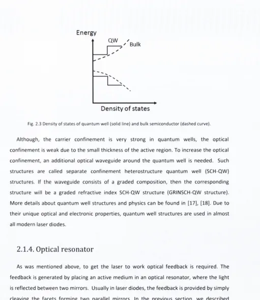
Fig. 2 .3 D e n s ity o f s ta te s o f q u a n tu m w e ll (solid lin e ) a n d b u lk s e m ic o n d u c to r (d a s h e d c u rv e ).
Although, th e carrier c o n fin em en t is very strong in q u an tu m wells, th e optical
c on fin em en t is w eak due to th e small thickness o f th e active region. To increase th e optical
con fin em en t, an additional optical w aveguide around th e q u an tu m w ell is needed. Such
structures are called separate c o n fin em en t h ete ro stru ctu re q u an tu m w ell (SCH-QW )
structures. If th e w aveguide consists of a graded com position, th en th e corresponding
structure will be a graded refractive index SCH-QW structure (GRINSCH-QW structure).
M o re details abo u t q u an tu m w ell structures and physics can be found in [17], [18]. Due to
th e ir unique optical and electronic properties, q u an tu m w ell structures are used in alm ost
all m odern laser diodes.
2.1.4. Optical resonator
As was m en tio n ed above, to g et th e laser to w o rk optical feed back is required. The
feedback is g en erated by placing an active m edium in an optical resonator, w h e re th e light
is reflected b etw e en tw o mirrors. Usually in laser diodes, th e feed back is provided by simply
cleaving th e facets form ing tw o parallel mirrors. In th e previous section, w e described
dou ble-h etero structures w h e re th e active region acts as a dielectric w aveguide due to
higher refractive index than th e c o n fin em en t layers. The dielectric w aveguide consists of
one or m ore guided transverse modes, which are polarized e ith e r transverse electric (TE) or
transverse m agnetic (T M ). Since th e active layer acts as a dielectric w aveguide, these modes
[image:28.553.31.543.31.620.2]layer is defined by the confinement factor
F ,
which is the fraction of the mode power confined in the active layer. If we will consider a symmetric dielectric waveguide with thicknessd,
and refractive index as shown in Fig. 2.4, then we can defineF
as follows:(2.5)
where \Ey\ is the amplitude of electric field (with assumption that TE mode is dominant).
The F factor is dependent on refractive index difference and the active layer thickness. The wavelength dependent modal gain, is given by this F factor and the active layer gain and w ritten as
F ig. 2 . 4 S c h e m a t i c c r o s s -s e c tio n o f a d i e l e c t r ic w a v e g u i d e w i t h t h ic k n e s s d . r i i is t h e r e f r a c t i v e in d e x o f a c t iv e l a y e r , a n d Uq is r e f r a c t i v e in d e x o f c o n f i n e m e n t la y e r s [ 1 0 ] .
The simplest type of a laser is a Fabry-Perot laser which typically consists of tw o cleaved facets with m irror reflectivity and
/?2
as depicted in Fig. 2.5. The backward-going and forward-going waves are defined by a propagation constantp
as in (2.1)d e f f ~ ^ 9 a - (2.6)
X
no
d/ 2
0
d
n i
-d/2
no
(2.7)
9 n e t ~ d e f f (2.8)
[image:29.553.15.536.32.515.2]P2 R2
Gain medium
P i
Fig. 2 .5 S c h e m a t ic v i e w o f F a b r y - P e r o t la s e r w i t h l e n g t h L a n d m i r r o r r e f l e c t i v i t ie s R j a n d /?2'
To satisfy a steady-state oscillation condition, th e ro u n d -trip gain o f th e cavity m ust be
equal to 1 and can be expressed as
r^V2e
=
1
,
(2.9)w h e re r j and r2 are th e a m p litu d e reflectivities. The im aginary and real parts o f equation
(2.9) give tw o d iffe re n t conditions, one is fo r th e a m p litu d e and th e o th e r is fo r th e phase
condition. From th e phase condition, th e ro u n d -trip phase is equal to an in teg er m u ltiple of
2n.
This will lead to th e resonance condition o f th e cavity and a standing w ave occursb etw e en tw o mirrors. This will fo rm a set o f longitudinal m odes w ith w avelength
X
=2rigfj^L
m
(
2.10)
and m ode spacing
A A p p —
X r
X.
m + l (2.11)w h e re n ^ ,e // is th e group refractive index.
The spectrum o f a Fabry-Perot laser is m u m o d e as it is shown in Fig. 2.6. The m u
lti-m ode spectrulti-m has negative consequences in long-haul fib er-o p tic colti-m lti-m unications due to
th e dispersion in th e fibers which can lim it th e achievable data transm ission rate. For this
purpose, a single-m ode laser is required. The ways to achieve a single-m ode o p eratio n will
-70
-1520 1530 1540 1550 1560 1570 1580 W avelength (nm)
Fig. 2 .6 Optical spectrum o f a Fabry-Perot laser w ith emission peak at 1 5 5 0 nm. T he individual lines are th e
longitudinal m odes o f th e laser.
2.2. Laser diode characteristics
2.2.1. The rate equations
The simplest way to describe the behavior of laser diodes is to use the rate equations.
These equations express the balance of carriers and photons in the system. The rate
equations for the carrier density
N
and the average photon densityNp^
in the active regioncan be w ritten as [10], [19]
where
Vg
is the group velocity,R ( N )
is the spontaneous recombination rate, is the cavitygain and
R^p
is the spontaneous emission into the lasing mode.For a steady-state case, carrier and photon densities do not change
dyv
/
d t ~ qVa
^adeffNph
R (N ).
(2
.11
)diV
dF = '’ ’
d t
Fig. 2.7 shows a schematic view of the output power as a function of current and carrier density as a function of current. The point where the output power increases linearly is called the threshold current which can be obtained from the rate equation (2.11), assuming that the photon density is zero
Itn = qVaR(Nt n), (2.14)
where the carrier density remains constant above threshold N = and this behavior is called gain-clamping.
Pout N
s tim u la te d emission
AP
Spontaneous emission
/
Fig, 2 .7 Schem atic view o f (left) o u tp u t p o w e r vs. c u rre n t, and (right) carrier d en sity vs. cu rre n t. Below laser thresh old th e re is no p hoton e m itte d e xcep t spontaneously e m itte d photons th e re fo re , th e laser o p erates in spontaneous emission m ode. Above thresh old , th e laser o u tp u t p o w e r increases linearly w ith th e cu rre n t. The c a rrier density has a constant value above thresh old and this e ffe c t is called gain-clam ping.
The photon density above threshold will be w ritten as
I - Itn
N h = --- (2.15)
where Uf-gf is the total cavity loss which is the sum of mirrors loss (a^j^) and internal loss
(2.16)
Above t h e t h re s h o l d cur rent , t h e laser o u t p u t pov\/er i ncr e ases linearly with t h e injection
cur rent . The differential efficiency
r j a
is def ine d as
w h e r e d P / d / i s t h e slope efficiency whi ch s h o ws t h e efficiency of a laser d i od e and
m e a s u r e d in a units of mW/ mA.
The left h an d side of Fig. 2.7 is usually r e fe r r ed as a l ight-current curve
o r L — I
curve.
From this curve it is possible t o d e t e r m i n e t h e basic characteristics such as t hr es ho l d
cur rent ,/ fft , a n d sl ope efficiency, d P / d / . Mor e ove r , fr om t h e L — / curve internal laser
p a r a m e t e r s can be calculated, including t h e internal optical losses a n d t h e q u a n t u m
efficiency of a laser.
The
L — I
curve is st rongly af fe c te d by t h e t e m p e r a t u r e an d t h e t h re s h o l d c ur re nt
c h a n g e s exponentially with t h e c h a n g e of t e m p e r a t u r e
w h e r e
T
qis t h e characteri stic t e m p e r a t u r e which def ine s t h e t e m p e r a t u r e stability of t he
device. F urt her exp l an at i o n a b o u t t h e characteristic t e m p e r a t u r e a n d t h e m e a s u r e m e n t
r esults will be given in C h a p t e r 5.
2.2.2. The spectral characteristics
T h e r e ar e t w o basic t y p e s of lasers, which ar e t e r m e d si ng le - mo de a n d m ul t i - m od e . We
have al re ady d e m o n s t r a t e d a Fabry-Perot laser o p e r a t i n g with a m u l t i - m o de s p e c tr u m. It
wa s m e n t i o n e d t h a t it has a n ega ti ve infl uence on d a t a t rans mi ss ion t h e r e f o r e , t h e spectral
purity of laser d io de s is crucial. In this sec t i on w e will i n t ro du ce s i ng l e- mo de o p e r at i o n .
A laser can be def ine d as a si ngl e-mode, if t h e ratio of t h e p o w e r in t h e s t r o n g e s t m o d e
d ete rm in es the single-m ode o p eratio n is called a sid e-m o d e suppression ratio (SMSR). The
SMSR can be calculated using rate equations [20] fo r steady-state condition
=
0
=R,p(A^) +
=
0
=RspiK^,) +
(2
.20
)w h e re m and m - I - 1 are the d o m in an t and the second strongest m odes, respectively. The
SMSR will be th e ratio of these modes
S M S R = (2.2 1)
^PUm+i
From the exp erim ental m easurem ents, th e SMSR can be calculated as th e d ifference in
th e optical p o w er of th e main m ode and th e next strongest m ode. An exam p le of this single
m o d e o p eratio n is d em on strated in Fig. 2.8. The optical p o w er of th e m ain m ode is -1 0 dBm
and th e optical p o w er o f th e next strongest m ode is around -56 dBm. Hence, th e SMSR of
th e given single-m ode laser is around 46 dB. It should be noted th a t th e SMSR u n it is given
in dB and not in dBm. The reason is th a t dB is used to evalu ate th e ratio b e tw e e n tw o
optical pow ers (intensities), w h ile dBm is used to q u an tify an absolute value o f th e pow er.
-10
-20
I -30
-40 0)
O -50 CL
...
-60-70
1550 1560 1570
1520 1530 1540
W a v e le n g th (nm )
Fig. 2.8 M ea s u re d optical spectru m o f a sing le-m od e laser.
T h ere are several ways o f achieving single-m ode o p eratio n such as m aking a laser cavity
t h u s onl y o n e m o d e will exi st n e a r t h e gain p e ak . O p e r a t i o n o n a s i n g l e - m o d e c a n b e also
a c h i e v e d by us i n g m u l t i p l e - m i r r o r r e s o n a t o r s [21]. E x a mp l e s o f a ch i e vi n g s i n g l e - m o d e
o p e r a t i o n a r e p r e s e n t e d in [11]. H o w e v e r , t h e m o s t w i d el y u s e d m e t h o d is t o u s e p e r i o di c
s t r u c t u r e s o r g r a t i n g s f o r m o d e selectivity. It s h o u l d b e m e n t i o n e d t h a t t h e l a se rs in t hi s
t h e s i s a r e b a s e d o n h i g h - o r d e r g r at i n g s . T h e d e t a i l e d d e s c r i p t i o n of g r a t i n g t h e o r y a n d t h e
e x a m p l e s o f l as er s e x p l o i t in g g r a t i n g s in t h e i r s t r u c t u r e s will b e gi ven in C h a p t e r 3.
2.2.3. The laser linewidth
S c h a w l o w - T o w n e s l i n ew i d t h
T h e s p e c t r a l l i n e wi d t h o f a l a s e r d i o d e is a n i m p o r t a n t p a r a m e t e r in c o h e r e n t
c o m m u n i c a t i o n s y s t e m s a n d in t h e s y s t e m s w i t h high o r d e r o p ti c a l m o d u l a t i o n f o r m a t s
[ di fferent i al p h a s e shi f t i ng keyi ng (DPSK) a n d d i f fe re nt i a l q u a d r a t u r e p h a s e shi ft keyi ng
(DQPSK)]. For t h e s e high s p e e d m o d u l a t i o n f o r m a t s , t h
![Fig. 1.2 Schematic diagram of optical heterodyne detection [3].](https://thumb-us.123doks.com/thumbv2/123dok_us/948811.607997/16.553.32.543.48.773/fig-schematic-diagram-optical-heterodyne-detection.webp)
![Table 1.2 Linewidth requirements for different modulation form ats for 40 Gbit/s link [4].](https://thumb-us.123doks.com/thumbv2/123dok_us/948811.607997/17.553.3.534.26.817/table-linewidth-requirements-different-modulation-form-gbit-link.webp)