Comparison by Simulation of Various Strategies of
Three Level Induction Motor Torque Control
Schemes for Electrical Vehicle Application
L. YOUB, A. CRACIUNESCU
Abstract — In this paper three new direct torque control strategies are compared with the classical direct torque control for an induction motor feed by a three level inverter. The considered new strategies are: direct torque control strategy with fuzzy logic regulators instead of hysteresis regulators, direct torque control strategy with hysteresis regulators associated with fuzzy logic regulators and direct torque control strategy with fuzzy, hysteresis and space vector modulation. The comparison is based on the simulation results obtained with MATLAB/SIMULINK program.
Key words— Induction machine, direct torque control, Fuzzy logic, Space vector modulation, three level inverter.
I. INTRODUCTION
Many control techniques have been applied on induction motors [1, 2]. Among these techniques, direct torque control (DTC) introduced by Takahashi appears to be very convenient for EV applications [3, 4]. Most of the literature is focused on the application of DTC with two-level inverters. However, DTC with a three level inverter is still a matter of research. The present work is based on the study of the application of DTC with the three-level NPC inverter, and the advantages that can be obtained. When using a three-level inverter the selection of the output voltage vector becomes more complex due to the higher number of available inverter states. For this purpose three different control methods have been designed. The first one is based on the conventional DTC scheme adapted for three-level inverter. The second one is based on a fuzzy
Manuscript received February 19, 2011; revised March 16, 2011. L.Youb is with University of Batna (Algeria), Science Engineering Faculty (e-mail: [email protected]).
A.Craciunescu is with University of Bucharest (Romania), Electrical Engineering Faculty (e-mail:
logic controller instead of hysteresis regulators for the inverter state selection. And the third one is a DTC strategy with fuzzy, hysteresis and space vector modulation. The required measurements for this control technique are only the voltage and the current measurements. Flux, torque, and current are estimated. The objective of this paper is to analyze the performance of the various DTC strategies on the sole induction motor used for electric vehicle application.
II. THE DIRECT TORQUE CONTROL ALGORITHM
The DTC algorithm, which is employed with a 3-level inverter, is a natural extension of the classical DTC to multilevel inverters. In this paper, the so-called diode clamped 3-level inverter has been used as shown in Fig.1. With such an inverter, the possible inverter switching states, for each phase, are shown in Tab.I where Sxis a variable that identifies the switching state
of an inverter leg. Each voltage space vector generated by the inverter is then identified by a 3-component vector, like (2 2 1), where each component is given by the value of Sxfor each of the three legs of the inverter:
Fig. 2 shows the hexagon of the 19 voltage space vectors which can be generated by such an inverter. The proposed DTC algorithm employs only 12 active voltage space vectors, divided into two categories on the basis of the parameter LevU(voltage level) as shown in
Fig. 1 Schematics of a 3-level diode-clamped inverter
As it can be seen from Tab.II, any ui space vector
(with i=1, 2, …,6) with LevU= low can be obtained with
two different switching patterns and this is exploited to avoid the capacitor voltage unbalance, as shown in §III.
TABLE. I
SWITCHING STATES OF A3-LEVEL INVERTER
SxA S1A S2A S3A S4A
2 On On Off Off
1 Off On On Off
0 Off Off On On
TABLE. II
VOLTAGE SPACE VECTORS EMPLOYED IN THE PROPOSEDDTCALGORITHM
u1 u2 u3 u4 u5 u6
LevU High 2 0 0 2 2 0 0 2 0 0 2 2 0 0 2 2 0 2
Low 2 1 1 2 2 1 1 2 1 1 2 2 1 1 2 2 1 2 1 0 0 1 1 0 0 1 0 0 1 1 0 0 1 1 0 1
The employed DTC block diagram, shown in Fig. 3, is the natural extension of the classical DTC. It shows that the closed-loop control of both the rotor speed and the stator flux linkage is performed. Employing a PI controller that processes the speed error obtained as the difference between the reference speed and the measured speed, which is obtained by the encoder as Fig. 3a, does speed control. The output of the speed controller is used as the reference torque. Both torque and stator flux controls are achieved by using 4-level hysteresis comparators (Fig. 3): the output this comparator (Toutfor the torque and Ψoutfor the stator-flux
linkage) can be either 2 (–2) or 1 (–1) according to the positive (negative) value of the torque or the flux error: if the value of the error is within the hysteresis loop, then the output of the comparator is 1 (-1) if the previous comparator output was 1 or 2 (-1 or -2). On the basis of the
Fig. 2 Hexagon of the voltages of a 3-level inverter
i (i=1, 2, …,6) in which the stator flux linkage lies and of the magnitude of the errors of the torque and flux loops, a voltage space vector ui(with i=1, 2, …,6 - see Tab.III) is
generated. In this control strategy, no null vector has been used to obtain the best dynamical performances of the electric drive, at the expenses though of higher ripples in the torque. If the absolute value of the output of one of the two the comparators is higher than two, then the voltage space vector ui with LevU=”high” is generated,
otherwise ui with LevU=”low” is selected. As clearly it
is shown in Fig. 4, the effect of the voltage space vector with LevU=”high” is to cause high variations both in the
torque and in the stator flux, while the effect of the voltage space vector with LevU=”low” is to cause
II. THE FUZZY DIRECT TORQUE CONTROL
In Fig. 4 is shown the block diagram of an induction motor drive system feed by a three-level inverter fuzzy regulators DTC system feed of an induction machine. The three-phase output voltage waveforms are generated by various switching combinations of the switches. The NPC three-level inverter and the induction machine are connected directly, and output transformer or filter is not necessary.
Fig.4 The schematic block diagram of an induction motor feed by a three-level inverter with DTC fuzzy controller and space vector modulation
To get a better control performance a fuzzy logic controller has been introduced to be a compliment to the hysteresis controller. The wide of the hysteresis cycle will be fuzzy variables:
b
for flux controller andb
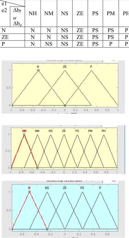
T for torque controller. The fuzzy controller design is based on intuition and simulation. These values compose a training set which is used to obtain the table of rules. The fuzzy rules' sets are shown in Table 1II. In Fig. 5 it is shown the membership functions of input and output variables and in Fig.6 it is shown the control surface. The rules were formulated using analysis data obtained from the simulation of the system using different values of the torque hysteresis band. The symbols used in Fig. 5 are the following: PH: positive high, NH: negative high, PM: positive medium, NM: negative medium, PS: positive small, NS: negative small, ZE: zero.The linguistic rules can be expressed by the following example: • If (e1 is NH or NM and e2 is N) then ( ΔbΓ
orΔbφis N):
This case corresponds to a big overshoot in torque error, consequently high torque ripple. To reduce the torque ripple, the value ΔbΓshould be reduced. In this case, the
overshoot in torque error can touch the upper band that will cause a reverse voltage vector to be selected. This one will result in a torque rapid decreasing that will determine undershoot in the torque response below the hysteresis band. Therefore, ΔbΓshould not be too small; ΔbΓis set Positive in order to avoid this situation.
III. SPACE VECTOR MODULATION
The aim of SVM is to minimize harmonic distortion in the current by selecting the appropriate switching vectors and determining their corresponding dwelling widths [5]. As depicted in Fig. 7 there are eight states available for voltage space vector according to eight switching positions of the inverter. SVM is based on time averaging techniques during sampling period Ts. If
the reference vector Vs (Vref = V1+ V2),is located in the
sector I (Fig.7), then it is composed of voltage vector V1 and V2 and zero vectors V0 and V7 [6]:
The SVM techniques use the following equations in the process of the synthesis of the reference voltage [6]:
1 2
7 0
2 1
T T T T
T s (1)
3 sin sin 2
1
a T
T s (2)
Several SVM strategies can be used for the piloting of the inverter. The only difference between these strategies is the choice of the null vector and the e1
NH NM NS ZE PS PM PH
e2 ΔbΓ
or
Δbφ
N N N NS ZE PS PS P
ZE N N NS ZE PS PS P
P N NS NS ZE PS P P
[image:4.612.68.295.110.527.2]FIG.7. Decomposition of voltage vector
[image:4.612.306.548.245.497.2]Fig. 6 Control surface
Fig. 5 Input/output variables membership functions
TABLE III
FUZZY RULES OF TORQUE AND FLUX HYSTERESIS CONTROLLER
[image:4.612.314.535.546.647.2] [image:4.612.69.290.562.659.2]sequence of application of the vector's tension during the period of sampling:
2 2 1 1
1Vs T V T V
T (3)
3 sin sin 2 1
a TT s (4)
where:
T1 and T2 are the active pulse times of voltage vectors V1 and V2, and
dc sV
V
a
3
2
Vdc: d-c link voltage.T0, T7 are a null vector times.
In Fig.8 is shown the novel DTC scheme for ac motor drives with fuzzy hysteresis and space vector modulation.
IV. SIMULATION RESULTS
The study of the performances of the fuzzy logic controller used with DTC strategy was made by simulation of the system by using MATLAB /SIMULINK and fuzzy logic tools. The problem was to find how to make the flux to rapidly reaching it’s given value, when the system is started with direct torque control. In the case of combined control strategy, where the hysteresis regulators are associated with fuzzy regulators and space vector modulation, the used membership functions were the same as in section II. The comparative results obtained by simulation for an induction motor are given in figures (10-12). It is interesting to note that, the torque pulsations in the case of fuzzy DTC with space vector modulation, as it is shown in figure (10), are smaller than in the case of classical DTC with fuzzy Hysteresis, as it is shown in figures 6. But the stator current in this case is bigger. The appropriate figures show the dynamics of the flux and of the torque of the induction motor. The trajectory of stator flux has a reduction of the ripples (figure.12), and trajectory of stator flux is circular. In the case of hysteresis comparators associated with fuzzy regulators one can obtain a fast torque response and good establishment time, as it is shown in figure.11. The simulation results highlighted the superior performances of the combined fuzzy- hysteresis DTC of the induction motor.
In the case of space vector modulation, as we can see from figure 12, the torque ripples are drastically reduced. These results are obtained in spite of using larger sampling period for the DTC with fuzzy associated regulator. The simulation results given in Fig. 12 shows a good tracking of electromagnetic torque using DTC with fuzzy associated regulators and SVM and prove that this technique allows a good dynamic performance similar to the basic DTC schemes. Moreover, it can be noted that the effects due to the crossing of sector boundaries, typical of basic DTC schemes, are avoided when it is used the DTC with hysteresis controller associated with fuzzy regulators scheme.
V. CONCLUSION
In this paper three new DTC strategies are compared with the classical DTC for an induction motor feed by a three level inverter. The analysis was made by numerical simulation. The advantages of the proposed fuzzy direct torque control using space vector modulation technique in comparison with a fuzzy hysteresis of DTC are the following:
– A reduced torque and flux ripples;
– A constant switching frequency due of the SVM presence;
– A fast torque response due of the fuzzy controller contribution;
– A lower sampling time;
– The absence of current and torque ripples caused by sector changes.
REFERENCES
[1] Casadei, D., serra, G., Tani, A, “Performance analysis of a DTC control scheme for induction motor in the low speed range“, in proceeding of EPE, (1997), p.3.700-3.704, Trondheim.
[2] Depenbrok. M, «Direct self-control (DSC) of inverter fed induction machine», In: IEEE Trans. On PE (1988), Vol. PE-3, No4, October 1988, p 420-429.
[3] A. Cataliotti, G. Poma: “A Fuzzy approach for easy and robust control of an induction motor”. EPE 97, pp 2.421-2.425, 1997. [4] J. R G Schonfield,”Direct torque control-DTC", ABB Industrial
Systems Ltd.
[5] Ned Gulley, J.-S. Roger Jang: Fuzzy Logic Toolbox for Use With Matlab". The Math Works inc, Natick, Mass, 1996. [6] H.Buhler: Réglage par Logique floue. Presses polytechniques et universitaires Romande, 1994.
E le ct ro m ag ne tic to rq ue ( N .m ) S ta ro r cu rr en t ( A ) E le ct ro m ag ne tic to rq ue (N .m ) S ta to r cu rr en t ( A ) E le ct ro m ag ne tic to rq ue ( N .m ) S ta ro r cu rr en t ( A )
Fig. 11. DTC with fuzzy logic with 3-level inverter a) Stator flux trajectory (Web), b) Electromagnetic Torque (N.m),c) Stator current (A),
Fig. 10. DTC Conventional with 3-level inverter : a) Stator flux trajectory (Web), b) Electromagnetic Torque (N.m), c) Stator current (A)
a). Stator flux trajectory (Web)
a) Stator flux trajectory
a). Stator flux trajectory (Web)
b) Time (sec) c) Time (sec)
b) Time (sec) c) Time (sec) b) Time (sec)