2589
©IJRASET: All Rights are Reserved
Applications
Vivek Dudhat
1, Prof. (Dr.) D.H. Pandya
21PG Student, Mechanical Engineering Department, LDRP-ITR, KSV University, Gandhinagar, Gujarat, India.
2Head of Mechanical Engineering Department, LDRP-ITR, KSV University, Gandhinagar, Gujarat, India.
Abstract: Microwave components plays a crucial role in communication system. To convey all types of information like voice, data links, wireless network, satellite and spacecraft communication system etc. One of the prominent microwave components, extensively used in communication satellites is amplifier. In this project work fabrication, joining and testing of microwave components is successfully performed. Fabrication of components of amplifier had been used in this project work performed using high precision Lathe machines. A special focus were given for development of circumferential edge Joint process of microwave components by using Micro Plasma Arc Welding process in Kovar, Monel-404, and Soft iron types microwave component’s materials and necessary fixtures used during welding for joining of microwave components. The leak proof joints has developed to sustain vacuum pressure of the order of 10-10 Torr. Micro Plasma Arc Welding process will providing quick,
better quality and defect free weld in the microwave components materials as compared to another fusion welding process. During my project work-study of Micro Plasma Arc Welding process parameters such as welding current, voltage, electrode work piece distance, duty cycle, gas flow etc. Moreover, the study of various non- destructive test, like X-ray Radiography test, Dye penetration test and special focus on Helium leak proof test was performed on the samples joined using Micro Plasma Arc Welding Process. Finally, suitability of advanced welding process like Micro Plasma Arc Welding Process have proved for Microwave components.
Keywords: Space qualified material, Micro Plasma Arc Welding, Non-destructive tests, Space applications.
I.INTRODUCTION
Welding is the process of joining together two pieces of metal so that bonding takes place at their original boundary surfaces. When two parts to be joined are melted together, heat or pressure or both is applied and with or without added metal for formation of metallic bond. During welding, the work pieces to be joined are melted at the interface and after solidification; a permanent joint can
be achieved.Sometimes a filler material added as a form of weld pool of molten material, which after solidification gives a strong
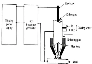
bond between the materials. Weldability of a material depends on different factors like the metallurgical changes that occur during welding, changes in hardness in weld zone due to rapid solidification, extent of oxidation due to reaction of materials with atmospheric oxygen and tendency of crack formation in the joint position. Plasma arc welding is an arc welding process similar to gas tungsten arc welding (GTAW). The key differences from GTAW is that in PAW, by positioning the electrode within the body of the torch, the plasma arc can separated from the shielding gas envelop. The plasma arc welding then forced through a fine-bore copper nozzle, which constricts the arc, and the plasma exits the orifice at high velocities and a temperature approaching 28,000 Degrees Celsius.
A. Basic Mechanism of Plasma Arc Welding Process
2590
[image:2.595.223.371.110.213.2]©IJRASET: All Rights are Reserved
Fig 1: Schematic Diagram of plasma arc welding process
B. Amplifier Microwave Components Materials
There are different types of materials used in fabrication of amplifier components. Micro plasma arc welding process is to be performed at materials like Kovar, Monel-404 and soft iron.
1) Kovar: Kovar is used for fabrication of amplifier components because of its unique property of thermal expansion. The
coefficient of thermal expansion of Kovar is 5x10⁻⁶/K for temperature range of 300C - 2000C.
2) Monel-404: Monel 404 alloy is used for fabrication of amplifier components because is used primarily in specialized electrical and electronic applications. The composition of Monel 404 alloy is providing to a very low Curie temperature, low permeability, and good brazing characteristics. Monel 404 can be welded using fusion welding techniques but cannot be used hot worked. Monel 400 series alloys good machinability and provide good weld joint.
3) Soft Iron: Soft Iron is used in fabrication of amplifier components because it is a low Carbon content ferrous alloy and finds its extensive use in amplifier components because it can be easily magnetized or demagnetized.
[image:2.595.74.520.413.582.2]C. Chemical Composition of Microwave Components
Table 1: Chemical composition of Kovar
Elements Ni Co Si C Mn Fe
Weight % 29 17 0.10 0.02 0.3 Balance
Table 2: Chemical composition of Monel-404
Elements Al Fe Mn Si Ni Cu
Weight % 0.05 0.5 0.1 0.1 52-57 Balance
Table 3: Chemical composition of Soft Iron
Elements C Fe
Weight % Very Low Balance
D. Fabrication of Microwave Components
Three types of materials used in fabrication of microwave components and Micro plasma arc welding process is performed on materials likes Kovar, Monel-404 and Soft iron. Following are the microwave components materials selection criteria:
1) Materials should have higher thermal conductivity and expansion.
2) Materials should have higher chemical resistance with excellent machinability.
3) Materials should have higher corrosion resistance and good weldability.
List of tools used on lathe machine for fabrication of microwave component
a) Turning tool
b) Facing tool
c) Boring tool
d) Drilling tool
2591
©IJRASET: All Rights are Reserved
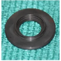
[image:3.595.244.351.332.440.2]
Fig 2: Kovar material Components
ii) Fabrication of Monel-404 components
Fig 3: Monel-404 material Components
iii) Fabrication of Soft Iron Components
Fig 4: Soft Iron material Components
II. EXPERIMENTAL WORK AND METHODOLOGY
Microwave components materials are welded micro plasma arc welding process with Circumferential Edge Joint by use in semi-automatic welding fixture. High purity argon gas (99.99%) is used as a shielding gas after welding to prevent absorption of oxygen and nitrogen from the atmosphere. Welding was carried out on Kovar, Monel-404, and Soft iron types space qualified materials. There are three types of non-destructive test used with accuracy by the space industry; they are the dye penetration test, X-ray Radiography test and Helium leak proof detection test.
A. Fixture Fabrication
To join Microwave components by Micro plasma arc welding method, it is essential to fabricate a cylindrical fixture lead to efficient supporting, holding, clamping and arresting the movement of the cylindrical type microwave components, which are joined, and hence resulting into quality welds. The layout of fixture is such that it need to provide rigid support to the cylindrical microwave components while welding and well mounted on the semi-automatic welding fixture. Fixture manufacture from Aluminium alloy 6061 and Stainless steel alloy.
B. Important Consideration for Fixture
1) A fixture is efficient for supporting, holding, clamping and arresting the movement of the cylindrical type microwave
components to be joined which results into quality welds.
2) The capability of welding fixture is to locate and hold all the cylindrical type microwave components and produced high quality
weld efficiently.
3) The welding fixture should provide rigid support to the cylindrical microwave components while welding and well mounted on
2592
[image:4.595.187.405.112.199.2]©IJRASET: All Rights are Reserved
Fig 5: Microwave components holding fixture
C. Experimental Parameters 1) Input Parameters
a) Material for Microwave components: Kovar, Monel-404, & Soft Iron
b) Weld joint: Circumferential Edge Joint
c) Technical parameters consider welding current, Gas flow, Electrode work piece distance, duty cycle, etc.
2) Output Parameters
a) A microwave components weld joint should be able to sustain vacuum pressure in order of 10-10 Torr.
b) Leak proof joint
c) Weld quality inspection through Non-destructive test (NDT) like Visual inspection, Dye Penetration Test, X-ray test, and
Helium leak proof detection test.
D. Experimental Procedure
Joining of Microwave components thickness very lesser (of the order of 0.5 mm) was selected as work piece material for the present experiment. Microwave components are fixed in the semi-automatic welding fixture with fixed welding torch and welding done Circumferential Edge Joint by use in non-transferred plasma arc welding process. Direct Current electrode positive was used in experiments as it concentrates the heat in the welding area. Thoriated Tungsten electrode (1% - 2% Thoria) of diameter 1 mm was taken as electrode for this experiment. The end of the electrode was prepared by grinding as the microwave components are having
very low thickness values & higher weld penetration are required for leak proof joints so Electrode vertex angle (Ɵ) is optimized
between 7-10 Degrees. For the experiment, micro plasma arc welding process parameters selected are show in table 4.
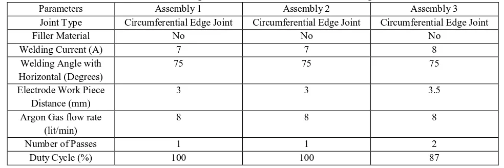
Table 4: Welding Parameters of Micro Plasma Arc Welding
Parameters Assembly 1 Assembly 2 Assembly 3
Joint Type Circumferential Edge Joint Circumferential Edge Joint Circumferential Edge Joint
Filler Material No No No
Welding Current (A) 7 7 8
Welding Angle with Horizontal (Degrees)
75 75 75
Electrode Work Piece Distance (mm)
3 3 3.5
Argon Gas flow rate (lit/min)
8 8 8
Number of Passes 1 1 2
Duty Cycle (%) 100 100 87
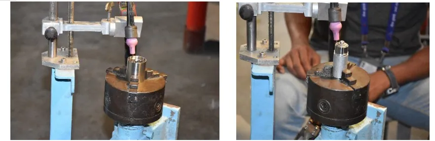
E. Sequential Procedural Methodology
[image:4.595.51.543.487.651.2]2593
©IJRASET: All Rights are Reserved
Fig 6: Microwave components holding fixture during welding
III.TESTING OF MICROWAVE COMPONENTS JOINED USING MPAW
After fabrication of microwave components, it is necessary to do test for evaluation of microwave components weld joints. Testing of microwave components weld joints by MPAW process is testing by non-destructive testing. The process of interaction does not damage the test object or impair its intended utility value. NDT methods range from the simple to the intricate. Visual inspection is the simplest of all. Surface imperfections invisible to they may be revealed by dye penetrant or magnetic methods. If serious surface detects are found, there is often little point in proceeding further to the more complicated examination of the interior by other methods like X-ray Radiography or ultrasonic testing and helium leak proof detection testing. Non-destructive testing generally use for all those inspection methods that permit evaluation of welds and related materials without destroying their usefulness.
The objective of non-destructive testing of joints should be,
1) To seek out discontinuities which has evaluated to the requirements of the quality standards.
2) To obtain clues from the causes from irregularities in the fabrication process.
Following types of Non-destructive tests performed on welded joints.
A. Dye Penetration Test
Dye penetration test also called liquid penetration inspection (LPI) test. It is a widely applied for surface weld quality check in industry base. A test also low-cost inspection method so used to locate surface-breaking defects in all non-porous materials. Die penetration test was performed on welded joints. This method have used to find cracks, porosity and incomplete flow in weld joints. A limitation of this test is only check to surface cracks no identify to inner cracks so further tests apply to check inner cracks. A test name is X-ray Radiography test & Helium leak proof test.
1) Inspection Steps
a) Pre-cleaning
b) Application of Penetrant
c) Excess Penetrant Removal
d) Application of Developer
e) Inspection
[image:5.595.80.521.109.252.2]f) Post Cleaning
2594
©IJRASET: All Rights are Reserved
B. X-Ray Radiography Test
X-ray Radiography test method is non-destructive test method that utilizes radiation to penetrate an object and to,
1) Record Images on variety of recording devices such as film.
2) Be viewed on a fluorescent screen.
3) Be monitored by various types of electronic radiation detectors.
Penetrating radiation has passed through the welded joint on to a photographic film, resulting in an image of the objects internal structure be deposited on the film. The amount of energy absorbed by the object depends on its thickness and density. Energy not absorbed by the object will cause exposure of the radiographic film. These areas will be dark when the film is developed. Areas of the film exposed to less energy remain lighter. Therefore, areas of the object where the thickness has changed by discontinuities, such as porosity or cracks, will appeared as dark outlines on the film. Inclusions of low density such as slag will appear as dark areas on the film while inclusions of high density such as tungsten will appear as light areas. All discontinuities are detect by viewing shape and variation in density of the processed film.
a) Screen: Lead screen b) Exposure Time: 0.3 min c) Processing Time: 5 min
d) Film Brand & Type: Kodak MX125 e) Film Density: 2.0 to 4.0
f) Source Size: 1.5 mm Dia × 1.5 mm Ht g) X-ray KV:160
The joints is tested under reference of ASME Sec. V Art. 2 & 22 and accepted under ASME Sec. Vlll Div. 1 UW 51.
C. Helium Leak Proof Detection Test
After fabrication of microwave components, it is necessary to do test for evaluation microwave components weld joints. Testing of microwave components weld joints by MPAW process was tested by helium leak proof detection test at in house facility. This test also called Mass spectrometer leak detection test.
Leak in microwave components weld joints are the unwanted throughput of air or any other gas into the system from the external environment. Leaks can arise from some cracks, defects in weld joint, holes, porosity in the microwave components weld joints or due to impurities and imperfection in welding joint area. Leak in microwave components weld joints the possibility to attaining desire level of vacuum pressure.
The art of leak detection and fixing is,
1) To choose the appropriate non-destructive testing method of detection from the good knowledge of magnitude of leak.
2) To pin point and quantify of leak.
3) To seal it with an appropriate mechanism.
Leak has be quantified in terms of the rate at a gas flows through the leaks at certain condition of pressure and temperature. The most commonly used term is however “Torr” in a vacuum system. Helium leak proof detection test method involves the use of some tracer gas, which does not contaminate the system, and quantitative measurement of the partial pressure of the tracer gas entering microwave components weld joints through leaks. The detection of tracer gas has carried out by first ionizing them and measure with mass spectrometer. Most widely and accurately used method for calculation of vacuum leak rate is helium leak proof detection testing. The Appropriate fixtures is developed for sealing and vacuuming the welded components.
For conducting helium leak proof detection test the required equipment are,
a) Helium gas as tracer gas
b) Leak detector
c) Helium mass spectrometer leak detector
2595
©IJRASET: All Rights are Reserved
2 4.7×10⁻¹⁰ mbar-l/sec Helium 4.5×10⁻¹⁰ mbar-l/sec NO
3 4.7×10⁻¹⁰ mbar-l/sec Helium 4.5×10⁻¹⁰ mbar-l/sec NO
IV. RESULTS DISCUSSION
A. Dye Penetration Test
Dye penetration test is a non-destructive test for testing of surface weld quality testing process by use of penetrant and developer spray. Conducting of this test, in both welding process weld joints in microwave components. Sufficient time provide after the developer has been applied to weld joints, a short time has allowed the dry developer to bolt or draw the red dye form a discontinuities and holes. Discontinuities are show as bright red indications against the white background of the developer. The result of this test is positive and no possible discontinues cracks and holes not found during visual inspection.
B. X-ray Radiography Test
X-ray radiography test is a non-destructive testing process. A method is both internal and external weld surface defects detect during a testing process. Volumetric weld defects such as slag inclusions and various forms of gas porosity has easily detected by radiographic techniques due to the large negative absorption difference between the parent metal and the slag or gas. During conducting of this test, both welding process weld joints in microwave components provide sufficient time as per ASME radiography standards. The joints has tested under reference of ASME Sec. V Art. 2 & 22 and accepted under ASME Sec. Vlll Div. 1 UW 51. No significant defects found in the joints. The result of this test is positive & not observed cracks, porosity in radiography x-ray images. Film radiography produces a permanent record of the weld condition, which has archived for future reference and provides an excellent means of assessing the welder’s performance and for these reasons; it is often still the preferred method for new job fabrication.
3. Helium leak proof detection test:
The microwave components weld joints tested by use of Helium leak proof detection test. This test also called Mass spectrometer
leak detection test. Helium mass spectrometer is an instrument commonly used to detect and locate small leaks. It is typically uses
a vacuum chamber in which a sealed with vacuum container filled with helium have placed. Helium leaks out of the container, and
the rate of the leak has detected by a mass spectrometer. A blank background leak rate is select to 4×10⁻¹⁰ mbar-l/sec. After
performing and monitoring this test, we can say that the result of this test is positive and no possible small leak found during this test.
This method provide leak rate up to 10-10 Torr. This test only provides absence or presence of leak into vacuum system.
V. CONCLUSION
For development of effective leak proof microwave components weld joints by Micro plasma arc welding process, it covers section of microwave components materials and fabrication of microwave components by use in lathe machine. The thickness of microwave components was very less so special holding fixtures were developed for welding. Defined experimental sequential procedural methodology for MPAW Circumferential Edge Joint. Testing of microwave components weld joints and evaluation of the results. During this project works all the aimed objectives has been successfully achieved. After completion of fabrication, welding and testing phase of microwave components, following points are concluded.
A. Fabrication of Microwave components of Kovar, Monel-404 and Soft iron type materials is quite difficult because of toughness
and hardness materials properties.
B. Micro Plasma Arc Welding is suitable process for joining microwave components of lesser thickness (of the order of 0.5 mm).
C. The joint quality obtained Micro Plasma Arc Welding process was excellent and welded joints produced the process have
2596
©IJRASET: All Rights are Reserved
VI.ACKNOWLEDGEMENTS
The authors thankfully acknowledge the contributions of my college guide Prof. (Dr.) D.H.Pandya, Head of Mechanical Engineering Department, LDRP-ITR, KSV University Gandhinagar to carry out my project work.
REFERENCES
[1] Balaji Chandrakantha, S. V. Abinesh Kumarb, S. Ashwin Kumarc, R. Sathishd “Optimization and Non-destructive Test Analysis of SS316L Weldments Using GTAW” 2013.
[2] S. Arunkumar, P. Rangarajan, K. Devakumaran, p. Sathiya, “Comparative study on transverse shrinkage, mechanical and metallurgical properties of AA2219 aluminum weld joints prepared by gas tungsten arc and gas metal arc welding processes” 2015.
[3] Manikandan M, Nageswara Rao M, Ramanujam R, Devendranath Ramkumar a, Arivazhagan N, Reddy G. Mb “Optimization of the Pulsed Current Gas Tungsten Arc Welding Process Parameters for alloy C-276 using the Taguchi Method” 2016.
[4] N. Ramakrishnan1, B. Chandra Mohan & S. Rajeshwaran “Experimental Investigation and Predict GTAW Process Parameters on AA6063” 2016.
[5] K. Devendranath Ramkumar, Shah Vitesh Naren, Venkata Rama Karthik Paga,Ambuj Tiwari, N. Arivazhagan “Development of pulsed current gas tungsten arc welding techniquefor dissimilar joints of marine grade alloys” 2015.
[6] Chen Chena, Xinqian Weia, Yong Zhaoa, Keng Yana, b, Zhanjun Jiab, Yuxiang He “Effects of helium gas flow rate on arc shape, molten pool behavior and penetration in aluminum alloy DCEN TIG welding.” 2017.
[7] Sadu Venkatesu, M. Gangaraju, S. Bhaskar and B. Vishnu Vardhana Naidu “A Study of Laser Beam Welding, Gas Tungsten Arc Welding and High Temperature Brazing Processes on Micro hardness and Tensile Strength of AISI Type 316 Stainless Steel” 2018.
[8] Sudhakaran. ra, Sivasakthivel. p.sb, Nagaraja.sc and Eazhil. k.md “The Effect of Welding Process Parameters on Pitting Corrosion and Microstructure of Chromium-Manganese Stainless Steel Gas Tungsten Arc Welded Plates” 2014.
[9] P. Naveen Kumar, Y. Bhaskar, P. Mastanaiah, CVS Murthy “Study on dissimilar metals welding of 15CDV6 and SAE 4130 steel by inter pulse gas tungsten arc welding” 2014.
[10] Aravinda pai, Irappa Sogalad, S. K Albert, Prabhat kumar, T. K Mitra, and S.Basavarajappa “Comparison of microstructure and properties of modified 9Cr-1Mo weld produced by narrow gap hot wire and cold wire gas tungsten arc welding” 2014.
[11] G. madhusudhan reddy, K. Srinivasa rao “Microstructure and corrosion behaviour of gas tungsten arc welds of maraging steel” 2014. [12] P. Paulraj, R. Garg “Effect of welding parameters on pitting behavior of GTAWof DSS and super DSS weldments” 2016.
[13] Jaiteerth R. Joshi, Mastanaiah Potta, Kumar Adepu, Ramesh Kumar Katta, Madhusudhan Reddy Gankidi “A comparative evaluation of microstructural and mechanical behavior of fiber laser beam and tungsten inert gas dissimilar ultra-high strength steel welds” 2016.
[14] Sanket C. Bodkhe, Dhananjay R. Dolas “Optimization of Activated Tungsten Inert Gas Welding of 304L Austenitic Stainless Steel” 2016. [15] Welding Handbook by American Welding Society Vol. 1, Vol. 2.
[16] https://en.wikipedia.org/wiki/Plasma_arc_welding