University of Southampton Research Repository
ePrints Soton
Copyright © and Moral Rights for this thesis are retained by the author and/or other
copyright owners. A copy can be downloaded for personal non-commercial
research or study, without prior permission or charge. This thesis cannot be
reproduced or quoted extensively from without first obtaining permission in writing
from the copyright holder/s. The content must not be changed in any way or sold
commercially in any format or medium without the formal permission of the
copyright holders.
When referring to this work, full bibliographic details including the author, title,
awarding institution and date of the thesis must be given e.g.
AUTHOR (year of submission) "Full thesis title", University of Southampton, name
of the University School or Department, PhD Thesis, pagination
A THEORETICAL STUDY OF THE
PERFORMANCE OF RESISTOJET NOZZLES
A Thesis
presented for the Degree of DOCTOR OF PHILOSOPHY
of the
UNIVERSITY OF SOUTHAMPTON in the
Faculty of Engineering and Applied Science
by
I. EDWARDS
ABSTRACT
FACULTY OF ENGINEERING AND APPLIED SCIENCE AERONAUTICS AND ASTRONAUTICS
Doctor of Philosophy
A THEORETICAL STUDY OF THE PERFORMANCE OF RESISTOJET NOZZLES Ian Edwards
The theoretical development of four computer models of resistojet nozzle performance is reported. Five main energy loss processes are accounted
for; these are (i) frozen chemical rate processes, (ii) finite rate vibrational relaxation, (iii) incomplete expansion, (iv) viscous flow
and (v) radial flow.
The nozzle flow is assumed to be composed of an inviscid core and a viscous boundary layer, where the boundary layer is represented by the patching together of similar solutions of the laminar boundary layer equations. General similar boundary layer equations have been developed which include the radial dependences accounting for trans-verse curvature. Four simplified classes of similar equations are identified, and extensive solutions have been obtained for the Falkner-Skan equation and a modified Falkner-Skan equation which includes the effects of transverse curvature, over the range of pressure gradient parameter, g, from 0. to 10. Vibrational relaxation is modelled by using an approximate sudden freezing criterion.
Performance predictions are presented for , CH^, CO^ and NH^ for plenum temperatures extending from 300 to 3000°K and plenum pressures
- 2
CONTENTS
Contents
List of Figures List of Tables Notation Acknowledgements Page i iv vii viii xiii
1. Introduction
1•1 General Background
1.2 Resistojet Engineering and Applications 1.3 Gasdynamics of the Resistojet Motor
1.3.1 Ideal Situation 1.3.2 Real Situation
1.4 Literature on the Theoretical Performance of Resistojets
1.5 Present Approach
1.5.1 Aims of This Work 1.5.2 Model Situation
1 - 3 1
1
2
6
6
7 22 25 2526
2. Analysis of Nozzle Performance 2.1 Introduction
2.2 Performance Analysis of Individual Losses 2.2.1 Ideal Performance
2.2.2 Frozen Chemical Rate Processes
2.2.3 Frozen Vibrational Relaxation Processes 2.2.4 Incomplete Expansion
2.2.5 Viscous Flow 2.2.6 Radial Flow
2.3 Overall Nozzle Performance Parameters
32 - 44 32 32 32 34 35 36 38 40 42
Laminar Boundary Layer Theory 3.1 Introduction
3.2 A Literature Review of Similar Solutions 3.3 The Boundary Layer Equations
3.4 The Similar Boundary Layer Equations 3.4.1 Derivation of Equations
Page
3.4.2 Boundary Layer Parameters 61
3.5 Similar Solutions 64
3.5.1 Class A Solutions 66
3.5.2 Class B Solutions 70
3.5.3 Class C Solutions 76
3.5.4 Class B Solutions 79
4. Vibrational Relaxation 84 - 100
4.1 Introduction 84
4.2 Potential Flow Parameters 87
4.2.1 Frozen Vibrational Energy 88
4.2.2 Equilibrium Vibrational Energy 89 4.2.3 Sudden Freezing Approximation to
Ronequilibrium Vibrational Energy 91
4.3 Sudden Freezing Model 93
4.4 An Approximate Model of Vibrational Relaxation
in NHg-Hg-Ng Mixtures 97
5. Computer Models of Nozzle Performance 101-121
5.1 Introduction 101
5.2 Calculation Procedure 103
5.2.1 Nozzle Geometry 103
5.2.2 Propellent Chemistry and Thermodynamics 104 5.2.3 The Boundary Layer - Isentropic Core
Iteration Procedure 108
5.2.4 Performance Parameters 110
5.3 Model Zero 111
5.3.1 Isentropic Core Calculation
(Vibrational Energy Frozen) 111
5.3.2 Application of Cohen and Reshotko's Approximate Boundary Layer Method to
Resistojet Nozzles 112
5.4 Model One 115
5.5 Model Two 118
5.6 Model Three 120
6. Results and Discussion 122-177
6.1 Introduction X22
6.2 Nominal Nozzle Geometry 123
6.2.1 Predictions of Model Zero 124
Page
6.2.2 Predictions of Model One 130
6.2.3 Predictions of Model Two 140
6.2.4 Predictions of Model Three 153
6.3 Variation of Nozzle Geometry 157
6.4 Comparison with Experiment 167
7. Summary Discussion 178
References 182
Appendix A Discussion of Mathematical Techniques Used in Solving the Similar Boundary
Layer Equations 188
Appendix B Literature Survey of Relevant Vibrational
Rate Data 192
Tables 198
Figures
List of Figures
1. Nozzle Configuration 2. Coordinate System
3. Variation of Prandtl Number and Viscosity Exponent 4. Shear Stress Profiles for Class A Similar Solutions
5. Velocity Profiles for Class A Similar Solutions 6. Variation of Dimensionless Wall Shear Stress and
Boundary Layer Integrals (Class A ) 7. A Comparison of Class A and B Profiles
8. Shear Stress Profiles for Class B Similar Solutions 9. Velocity Profiles for Class B Similar Solutions 10. Variation of Wall Shear Stress, f"(o) (Class B)
•'^00
11. Variation of P^ = (l-f'^)dn (Class B)
12. Variation of P^ =
13. Variation of P^ =
f'(l-f')dn (Class B) 0
^=0
f'^dn (Class B)
o
14. Shear Stress and Total Enthalpy Function Gradient at Wall (Class C)
15. Comparison of Shear Stress Profiles (Class A and D ) 16. Total Enthalpy and Velocity Profiles (Class D) 17. Shear Stress and Total Enthalpy at Wall (Class D ) 18. Boundary Layer Integrals (Class D )
19. Flow Diagram of Nozzle Programs 20. Viscosity Data
21. Convergence of Boundary Layer - Inviscid Core Iteration Procedure (Model One)
22. Correlation Parameters of Cohen and Reshotko 23. Variation of ^-dependent Parameters (Model One) 24. Frozen Flow Losses (Model Zero)
25. Viscous Flow Losses (Model One)
26. Overall Nozzle Performance (Model Zero) 27. Frozen Vibrational Energy Loss (Model One) 28. Velocity Defect due to Viscous Flow (Model One) 29. Discharge Coefficient (Model One)
30. Axial Temperature Profiles (Model One)
31. Radial Velocity Profiles for Nominal Case (Model One) 32. Velocity Profiles at Exit Plane (Model One)
33. Development of Displacement Thickness (Model One) 34. Skin Friction Coefficient (Model One)
35. Variation of Form Factor 36. Radial Flow Loss (Model One)
37. Vibrational Energy Losses of CO^ and CH^ (Model Two) 38. Axial Temperature Profiles for CH^ and CO^ (Model Two) 39. Effect of Vibrational Rate Parameter, on
40. Effect of Plenum Pressure on Vibrational Energy Loss of CH^ 41. Effect of Vibrational Relaxation on Performance of CH, and C0„
4 I
42. Vibrational Energy Loss of NH^
43. Effect of Vibrational Relaxation on Performance of 44. Variation in Nozzle Efficiency with NH^ Dissociation
45. Boundary Layer Thicknesses at Nozzle Exit (Models One and Three) 46. Viscous Flow Velocity Defect - Comparison of Models One and Three 47. Variation of Discharge Coefficient with Throat Geometry
48. Incomplete Expansion Loss
49. Dependence of Viscous Flow Loss on Nozzle Area Ratio 50. Variation of Nozzle Efficiency with Area Ratio
51. Optimisation of Nozzle Area Ratio
52. Variation of Nozzle Efficiency with Divergent Half Angle 53. Optimum Divergent Half Angle for Conical Nozzles
55. Effect of Shape of Divergent Section on Nozzle Efficiency 56. Comparison with Experimental Discharge Coefficient
Measurements of Tang
57. Comparison with the Viscous Nozzle Experiments of Rothe 58. Comparison with Experimental Results of Yevseyev
59. Ammonia Performance - An Experimental Comparison 60. Methane Performance - An Experimental Comparison 61. Carbon Dioxide - An Experimental Comparison
List of Tables
I Class A Similar Solutions
II Class B Similar Solutions
III Class C Similar Solutions
IV Class D Similar Solutions
V Molar Heat Capacity, Polynomial Coefficients
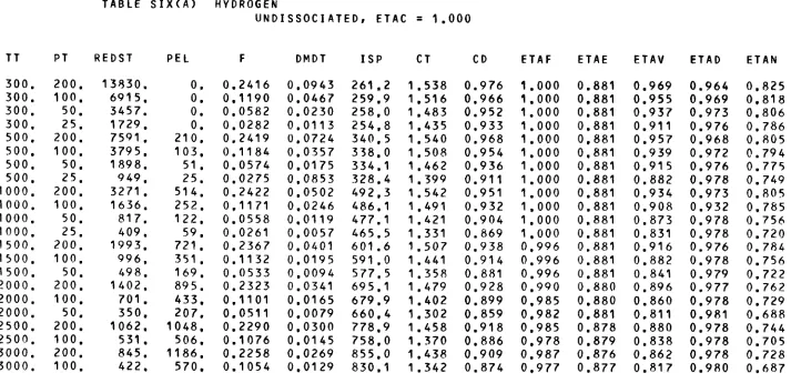
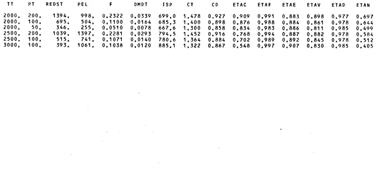
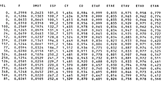
VI Resistojet Nozzle Performance Parameters
(a) Hydrogen (b) Methane
(c) Carbon Dioxide (d) Ammonia
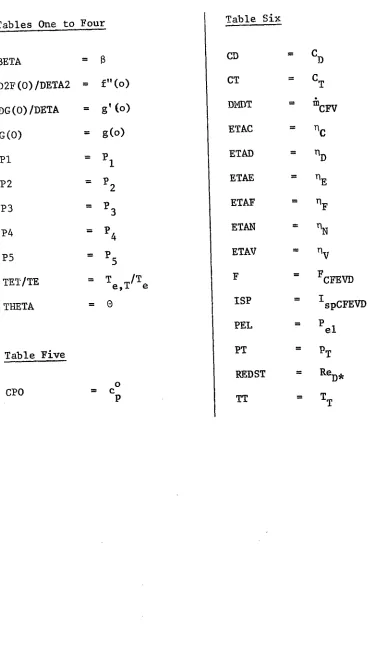
NOTATION
A Area
A and B Constants in the Landau-Teller equation, eq. (4.29) A^ Polynomial coefficients used in eq. (4.15)
B Reynolds number based on stagnation conditions and throat radius, B = p^(2H^)^R*/y^
Discharge coefficient, eq. (2.40)
Thrust coefficient, eq. (2.49) 0^2 Binary diffusion coefficient
F Thrust
G Ratio of local to geometric radius, G = r/R H Total enthalpy per unit mass, H = h + u^/2 H Transformed form factor
tr
AH° Heat of formation f
Specific impulse, eq. (2.48) Kn Knudsen number
Kp Equilibrium constant
Factor defined by eq. (5.22) L Nozzle wall length
M Mach number
M Molecular weight
N Momentum parameter
P Power
Pr Prandtl number, Pr = pc^/k
P to Pg. Boundary layer integrals of similar solutions, eqs. (3.68) to (3.72)
R Nozzle radius
R Radius of curvature at nozzle throat c
• "~X o "1
R Universal gas constant, R = 1.987 cal mole K
u u
R^ Nozzle inlet radius Rg Nozzle exit radius
S. Specific gas constant, R = R^/M
* * *
Re^^ Reynolds number based on throat diameter, Re^* = 2p u R /y^ A * ,
Re^ Reynolds number based on wall length, Re^ = p u L/y^ S Dimensionless enthalpy function, S = H/H^ - 1
T Temperature
Vj Jet velocity
Mole fraction of i^^ species
a and b Constants used in eq. (5.1) to define shape of nozzle divergent section
c^ Skin friction coefficient, eq. (3.64) i=n
c Molar heat, c = / c .
P P iti P,i
c Specific heat, c = c /M
P P P
e^ Vibrational energy per unit mass
f Dimensionless stream function, eq. (3.26)
also, mole fraction of undissociated NH^ not included in equilibrium calculation
g Dimensionless total enthalpy function, g = H/H^ —2 g^ Acceleration due to gravity, g^ = 9.80665 ms h Static enthalpy per unit mass
k Thermal conductivity
^ Shear parameter
m Mass flow rate
n Correlation parameter
p Pressure
q Distribution of heat sources in potential flow q^ Rate of heat transfer at wall
r Local radius
also, recovery factor , eq. (3.79) s Entropy per unit mass
u Velocity in x-direction V Velocity in y-direction
X Coordinate in direction parallel to wall y Coordinate in direction normal to wall
Distance from wall in radial plane, y^ = y cos a z Distance along axis
Axis length
z^ Axial distance in divergent section (see figure on page 104) a Local wall angle
Effective nozzle half angle at exit a^, Degree of dissociation
B Pressure gradient parameter, eq. (3.40) Y Ratio of specific heats, Y = c^°/(,c^ - R^) 6 Boundary layer overall thickness
<5 Boundary layer displacement thickness
e Nozzle area ratio, e = Exit area/Throat area n Transformed y-coordinate, eq. (3.23)
With subscripts an efficiency c* efficiency, eq. (2.53)
n Value of n for which u/u = 0.995
e e
Value of n for which j 1 - u/u^ | ^ 10 ^ 6 Boundary layer momentum thickness
0^ Nozzle wall angle at start of convergent section 62 Nozzle wall angle at start of divergent section A Ratio of density-viscosity product, A = pp/p y w w y Coefficient of viscosity
V Kinematic viscosity
K Transformed x-coordinate, eq. (3.22)
P Density
o Hypersonic parameter, a = u^ /H^ T Characteristic time
Dissociation time Local flow time
4" Factor in vibrational rate equation, eq. (4.30) also, quantity defined by eq. (5.23)
4> Stream function
0) Exponent in viscosity-temperature power law, eq. (3.42) 0 Transverse curvature parameter, eq. (3.46)
$ Rate parameter used in eq. (4.34)
Superscripts
* denotes throat
' denotes differential
denotes transformed plane (Cohen and Reshotko theory)
Subscripts
c denotes frozen chemical rate processes D denotes radial flow
E denotes incomplete expansion
F denotes frozen vibrational rate processes H denotes heater
N denotes nozzle
R denotes recombined state Res denotes resistojet
T denotes total or stagnation V denotes viscous flow
a denotes adiabatic wall d denotes radial plane
e denotes freestream or inviscid core eff denotes effective inviscid flow el denotes electric
eq denotes equilibrium conditions ex denotes nozzle exit plane fp denotes freezing point
g denotes gas at entrance to nozzle hi denotes heater losses
j denotes jet
mix denotes mixture
nl denotes nozzle losses
pr denotes propellent at 300°K trans denotes transit
tr denotes transformed plane (Cohen and Reshotko theory)
V denotes vibration w denotes wall conditons
Acknowledgements
The author would like to thank the following people:
Foremost, Dr. R.E.vJ. Jans son, who, as project supervisor, has provided much help and encouragement in the course of the work and in the preparation of this thesis.
Professor K.N.C. Bray, for many illuminating discussions and useful suggestions.
Mr. ¥.T. Lord, of the Rocket Propulsion Establishment, Westcott, for his help, interest and encouragement.
Mr. A.G, Earl, of the Royal Aircraft Establishment, Farnborough, for numerous discussions on the practical difficulties involved
in resistojet research and development.
Last, but not least, to Lynne, for typing this thesis and becoming my wife.
Chapter One Introduction
1.1 General Background
The work presented in this thesis originates from an interest in the use of resistojets for various propulsion duties on spacecraft. A subject of some importance in the design of resistojet systems is the performance of the resistojet motor. It is this topic which is examined here, and in particular theoretical models are reported of the energy loss processes found in the nozzle flow.
A resistojet motor is a low-thrust rocket, consisting of a heater and a convergent-divergent nozzle. It is essentially an energy conversion device in which the heater converts electric power to thermal energy by resistance heating, the heat subsequently being transferred to the gas stream, adding to the energy inherent in the propellant. Upon expansion through the nozzle the internal energy of the propellant is converted to kinetic energy. In a conventional chemical rocket, the heat release
accompanying the chemical reaction between the fuel and oxidant provides an energy source, whereas in the resistojet motor the main source of energy comes from an external electric power supply. Thus of the forms of electric propulsion - electrothermal, electrostatic and electromagnetic - the resistojet provides the simplest example of electrothermal
p r o p u l s i o n . O n account of its low thrust (less than 10 N) the resistojet, like all other forms of electrothermal propulsion, is suitable only for operation in a space environment.
The most important property of rocket performance is the exhaust velocity, which in an ideal situation is limited by the enthalpy per unit mass, or specific enthalpy, of the propellant. This in turn is limited by the heater stagnation temperature and therefore by the maximum temper-ature which can be tolerated by the resistojet structure. Propellants with the highest specific enthalpy are the gases with low molecular weight.
-The gases suitable for use in resistojets which are considered here are hydrogen, methane, ammonia and carbon dioxide. While not a complete list of the possible propellants, these gases cover a wide range of performance
- 1
capabilities, from an ideal exhaust velocity of 11.2 kms for at a stagnation temperature of 3000°K (an upper temperature limit), down to 0.67 kms ^ for CO^ at 300°K. In reality these theoretical values are never achieved, since the conversion of thermal energy to kinetic energy
(2)
in the resistojet motor is not an ideal process. Thus Page et al
-1 .
measured a jet velocity of 8.22 kms 3 with a hydrogen resistojet at a O
temperature of 2400 K, compared to an ideal jet velocity of 9.36 kms , in other words an energy conversion efficiency of 0.77. In this study it is intended, by taking into account the various energy loss processes occurring in the nozzle flow, to make more realistic predictions of resistojet nozzle performance.
The rest of this chapter is divided into four parts. In the next section the development of the resistojet motor and of the resistojet system are discussed, and useful applications to space missions are
considered. The physics of the gas flow through the heater and nozzle is examined in section 1.3, and particular emphasis is given to the losses incurred in the nozzle flow. This is followed in section 1.4 by a review of the literature on theoretical performance of resistojets. In the final section the aims of this research are described, the features included in the model of nozzle performance are defined and the contents of this thesis are outlined.
1.2 Resistojet Engineering and Applications
The first published reference to the concept of a resistojet motor d t / 4 ) (3)
was due to Jack in 1961, and it was a relatively straightforward task to demonstrate the concepts feasibility in the laboratory. Howard
reported in 1962 on the performance of a hydrogen resistojet, where, for
-an input power of 30 kW, a thrust of 6.04 N was measured, giving a specific impulse of 846 seconds. Additional complication is encountered when con-sidering a resistojet for use in space, since the motor is then part of an independent system. The hardware of this system consists basically of four parts; propellant tankage, power source, control equipment, i.e. electronics, valves and feed lines, and the motor itself. Two consumable quantities, the propellant flow and electric power provide the primary inputs to the resistojet motor. A schematic of the resistojet system is shown below.
jet of directed Mozzle
{thermal energy ______ ^ k l n e U c energy) Wnetk Heater
(thermal energy of gas increased) propellant
Propellant Storage
Power Source
Resistojet System
In designing a system to operate in space, constraints are imposed which are not present in the laboratory. These constraints, affecting not only the resistojet system but the whole spacecraft, arise from:
(1) the limited mass which can be raised to a given orbit, and (2) the limited amount of electric power available.
A major factor in the system design must be the mission for which it is required and a brief discussion of resistojet applications is in order.
Uses of resistojets fall into two broad categories, auxiliary propulsion and prime propulsion. Most spacecraft require some form of auxiliary
propulsion for such functions as manoeuvring, station keeping and attitude control. Nearly all low-thrust (less than ION) systems used to date have been based on cold flow gas jets, e.g. the cold nitrogen jets on the Mariner
a cold jet into a resistojet, weight savings and improved performance resulto In this case the design involves trading-off the decreased propellant mass requirements against the increased mass of the power
supply. Low-thrust resistojets, of the order of 50 mil, with power con-sumptions of the order of 10 - 200 W have been used, or are proposed for, the various satellite control duties.
Lord,^^^ and studies for the Manned Orbital Research Laboratory^^^, have shown that the payload in final orbit can be increased significantly by injecting a satellite or spacecraft into a low parking orbit using a conventional chemical booster, and using large resistojets (thrust of order 1 N ) to increase the orbital altitude by means of a spiral transfer
trajectory, rather than by boosting the payload to altitude directly. The penalty is an increased transfer time. In a subsequent study Lord and Parkinson^^^^ have widened the scope of their work by demonstrating the advantages of combining resistojets with ion motors to produce mixed thruster systems of versatile performance. Recent calculations
using a two-stage transfer for large communications satellites, indicate that not only is a good trade-off between payload and transfer time possible, but also that the system offers substantial economic savings.
The importance of a mission analysis to the design of a resistojet system is that it specifies (i) the total impulse requirement and
(ii) the power and mass allocations. In general the power and mass allocations are not independent of one another, and it is convenient to think of the electric power supply in terms of an equivalent mass. Solar arrays provide the usual power source for long duration space missions, so that the mass per unit power of the array is an important quantity. One approach to the design of resistojet systems is to minimise the system
(12)
mass . This involves an optimisation of several conflicting factors. The factors involved
are;-(1) Mass per unit power of the solar array.
equipment, resistojet motor and thermal shielding. (3) Mass of propellant, which depends on the propellant
properties and on the performance of the resistojet motor.
It is the final factor which is investigated in this thesis.
The type of mission has obvious implications for the choice of propellant. Thus for missions of restricted lifetime, such as the
orbital transfer of large space vehicles, hydrogen, with its large specific enthalpy and consequent high exhaust velocity, is the best choice of
p r o p e l l a n t . F o r missions, such as satellite attitude control, in which resistojets would be operated in a pulsed mode over a period of
several years, then the use of hydrogen, which has to be stored
cryogenically and therefore has a restricted storage lifetime, is not feasible. For such duties other gases, such as ammonia and hydrazine, stored indefinitely as saturated liquids in a simple, thin-walled,
(13)
pressure tank, are attractive propellants. In manned space operations, the biowaste products of the environmental control/life support system such as carbon dioxide, methane and water can be used as resistojet p r o p e l l a n t s . I t follows that propellant supply and storage problems are then minimised, although intrinsically they are not such good propellants.
To sum up, however good the other components of the system, it is the performance of the resistojet motor which ultimately determines the usefulness of the system, so that prediction of the motor performance is very important. As already indicated the conversion of thermal energy to kinetic energy suffers from various losses, and in the next section the processes causing a reduction from the ideal performance are
examined.
-1.3 Gasdynamics of the Resistojet Motor
In order to simplify matters, attention is restricted in the present work to steady state operation, i.e. the resistojet motor receives a continuous supply of electric power and propellant. The models which are subsequently developed are therefore only strictly applicable to con-tinuous operation, but it will be shown that as far as the nozzle performance is concerned these models can also be applied to pulsed operation.
1.3.1 Ideal Situation
In the ideal situation all the electric power transferred to the heater is used in increasing the thermal energy content of the propellant, in other words increasing the total enthalpy. Further, during expansion through the nozzle the propellant internal energy is converted into kinetic energy directed along the nozzle axis. Thus the energy put into the resistojet motor, by the propellant and that added as electrical energy, is converted entirely to jet energy at the nozzle exit.
There are several implications in this definition which are useful when considering the real situation. The assumption that all the
electric power is converted into the internal energy of the propellant implies that no heat transfer losses occur through radiation or conduction from the resistojet body. It further implies that the gas flow through the heater and nozzle is non heat-conducting and inviscid. From a
macroscopic viewpoint the gas is regarded simply as a thermal energy sink in the heater and as a kinetic energy source in the nozzle. At the
microscopic level this definition demands that the internal energy processes react to changes in the equilibrium conditions with an infinitely fast rate. Since all the internal energy is assumed to be converted to kinetic energy, it is further implied that at exit from the nozzle the gas temperature is zero, so that all molecular and atomic excitation has ceased.
-The ideal situation in terms of energy flow, i.e. power, is
presented schematically below.
Ppr Electric Power
Jet Power Gas Power
Inherent Powe^
Heater
Nozzle
Ideal Resistojet Flow
A power balance for this ideal case gives
(a) Heater
(b) Nozzle
P , + P = P
el pr g
P g = P . ]
(c) Overall P + P = P .
el pr J
A n overall resistojet efficiency is then
'Res
P. J
Pel + P p r
(1.1)
(1.2)
(1.3)
(1.4)
and in this case
^
1.3.2 Real Situation
Some hint has already been given of the non-idealities occurring in
the real flow. Thus, there are losses due to tadiation from the heater
directly to space, and due to conduction to the spacecraft body and
nozzle, where it is subsequently lost by radiation. These heat transfer
losses mean that not all of the electric energy is transferred to the
propellant. Within the propellant flow there are various non-ideal
gas-dynamic processes, not all necessarily causing a reduction in performance
but complicating the picture. The gasdynamic problem is conveniently
considered in two parts, (a) heater flow and (b) nozzle flow.
-7-(a) Heater flow
There are a variety of heater designs (see, for instance Ref. 1,
pages 104 - 105) and of the most recent configurations the most promising
(2)
appear to be the concentric tubes scheme of Page et al and the vortex
heater of Murch and K r i e v e ^ ^ ^ \ Two factors which may influence the
performance of a resistojet heater are thermodynamic nonequilibrium and
viscous flow. Considerations of these two phenomena are restricted to
tubular heaters where it is easier to assess semi-quantitatively what
is happening.
Thermodynamic nonequilibrium and rate processes
The establishment of thermodynamic equilibrium between the various
internal energy modes - translation, rotation and vibration - and chemical
equilibrium do not occur instantaneously but require finite times. Since
the time taken for the gas to flow through the heater may be short, some
of the processes occurring in the flow may not have time to equilibrate.
Suppose that the time required to approach equilibrium can be represented
by a time T , which is a "relaxation" time for the energy mode or a
chemical time for the chemical reaction, then an initial prediction of the
occurrence of nonequilibrium can be made by comparing the various
characteristic times, T , with the transit time through the heater,
(16) ratio T/T has two limiting cases; if T/T -> 0
trans. trans trans
the process is very fast in comparison to the transit time, and equilibrium
conditions exist at exit. At the other extreme, with the transit time
very fast in comparison with the characteristic time, i.e. T/T ,
trans
the process effectively does not take place. Nonequilibrium can occur in
an excitation environment, as in the heater flow, or in a de-excitation
environment, as in the nozzle flow. The characteristic time describing
a process in these situations is different, with the de-excitation time
being considerably shorter than the excitation time (see Ref. 16, p. 151).
assumed that the "relaxation" time is identical in both situations. The transit time for the heater of Page^^^^ is calculated to be of the order of 100 msec; as this is a large device, typical transit times can be taken to be in the range 10 to 100 msec. Relaxation and chemical times are functions of temperature and pressure, and in general they are inversely proportional to pressure and increase exponentially with decreasing temperature. Translational and rotational energy modes
~9 (18)
relax very quickly, with times typically of 10 sec. for most gases , so these modes may be considered to be in equilibrium. Vibrational
relaxation is somewhat slower. Rate data gathered from the literature is presented in Appendix B, and it can be seen from Fig. B1 that, for the
polyatomics CO^, CH^ and the vibrational relaxation time, is ""5
less than 10 sec. at a pressure of 1 atm. for temperatures above 300 °K. The vibrational mode of is not significantly excited until temperatures greater than lOOO^K, where pT^ < 10 ^ sec. For the above gases vibration can be taken to be in equilibrium through the heater. However which is a product of the dissociation of NH^, relaxes very
o —^ ^
slowly and even at 2000 K, px^ 1 10 atm.sec. A decision regarding vibrational noneq.uilibrium in nitrogen is delayed until after an examination of the chemical times.
(19) The equilibrium constants of formation taken from the JANAF tables indicate that under equilibrium conditions NH^ would begin to dissociate into and at temperatures above SOO^K, but in practice kinetic
considerations suggest that significant decomposition does not occur until a much higher temperature. Reaction rate data for NH^ is sparse.
S a w y e r n o t e s that temperatures in excess of 1500°K were required to produce measurable ammonia decomposition from the homogeneous reaction.
( 2 3 )
Calculations based on the rate data of Michel and Wagner ' for NH^ in
- 2 o
Ar diluent, indicate a dissociation time, = 0(10 )sec. at 2000 K. The decomposition rate is increased by heterogeneous catalysis on the
metallic heater surfaces and shorter dissociation times axe suggested ( 2 2 )
by the data of Logan and Kemball . Approximate calculations give T^(NH ) = 0(10~^) sec. at 1500°K and T^(NH ) = 0(10~^) sec. at 2000°K.
(23)
Miles in a study of the catalytic dissociation of NH^ by various surfaces for temperatures up to 800°K, found substantial decomposition at comparable mass flows to those of present interest, but with space velocities (mass flow rate/area) about two orders lower. Finally
(24)
Perroud has investigated NH^ decomposition in tungsten tubes over the temperature range from 1000 to 3000°K. The findings of Refs. 20 to 24 indicate that dissociates in two phases, as a gas phase reaction and as a wall catalysed reaction. A ''threshold" temperature for significant homogeneous dissociation to commence exists at about 1500 to 1600°K. Heterogeneous reaction occurs at lower temperatures with "threshold" temperatures reported to vary from 1200°K^^^^ down to 4 0 0 ° K ^ ^ ^ \ The concept of a threshold temperature is misleading, since the heterogeneous catalysis requires collision of the propellant molecules with the heater wall, while the homogeneous reaction is slow at typical resistojet
temperatures (less than 2000°K). Under these conditions the chemical rate can be diffusion limited and even though the temperature is high enough to cause dissociation, the bulk of the gas may be convected through the heater before more than a fraction of the total number of molecules has a chance to react on the wall. It is difficult to infer much from the references about resistojet operations since the experimental
geometries and residence times are so different from those of resistojet heaters. However, it is to be expected that at low temperatures (300°K) NH^ will remain undissociated, and by 2000°K, say, a considerable amount of decomposition will occur. Experimental work is under way in this
laboratory to measure ammonia dissociation in typical resistojet heater c o n f i g u r a t i o n s .
mixture of and NHg. It is well knovm that mixtures in which there is a fast relaxing component, such as NH^, relax at a rate compar-able to that of the fastest component (see section 4.4). Thus it is reasonable to assume that for the gases considered here vibrational energy is in equilibrium at exit from the heater.
Of the other propellants, and can also dissociate under resistojet heater conditions. It is observed in resistojet experiments employing CH^ (26,15) deposition of solid carbon occurs at high
temperatures. Halbach^^^^ using a large concentric tube heater determined an upper operating temperature of 1000°K, whereas Murch and Krieve^^^^ using a small vortex heater note that no measurable carbon deposition occurs below 1900°K, The difference between these observations is almost certainly caused by the different heater transit times. Equilibrium calculations for indicate that only a small amount of dissociation occurs at temperatures below 2000°K. This fact allied to = 0(1)
sec, based on calculations of the rate data from Refs. 27 and 28, suggests that the presence of atomic hydrogen is unlikely at temperatures below 2000°K, and even at higher temperatures it will be present only in very small quantities.
The effect of nonequilibrium in the chemical rate processes is a reduction in the power put in to the nozzle, P^. In the case of CH^ a reduction in is preferred to the deposition of solid carbon.
Viscosity and heat conduction
Further nonequilibrium processes which must be considered in a real gas are viscosity and heat conduction. In resistojet heaters with the stagnation pressure typically of order of 1 atm, the flow is a continuum, so the condition of no slip at the heater surface applies. Thus the gas layer adjacent to the heater wall has zero velocity and its temperature is identical to that of the wall. Gradients in velocity and temperature are set up in a direction normal to the flow since momentum and energy
-are being transported througft. the heater by the propellant molecules. These gradients give rise to the phenomena of viscosity and heat conduction.
The effects of viscosity and heat conduction extend throughout the heater flow, and for the low speeds and small dimensions typical of resistojet heaters the flow should be laminar. From the aspect of con-verting electrical energy to thermal energy this is not advantageous since the heat transfer is less efficient than in a turbulent flo\7. Viscous flow causes a loss in momentum due to skin friction which is reflected in a drop in the total pressure. The overall effect of viscosity and heat conduction is dissipative in that it causes a
reduction in the gas power, P^. Unlike the thermodynamic rate processes, no general conclusions can be made regarding the magnitude of the viscous losses without a thorough analysis based on particular geometries.
Although the rate processes and the phenomena of viscosity and heat conduction have been considered separately, in fact they occur sirultan-eously and interact. In particular the chemical rate processes will couple with the viscous flow. Thus the heterogeneous decomposition of ammonia, occurring at the heater surface, does so in a region of reduced velocity and therefore increased residence time. It follows that at a given position there will be a gradient in the gas composition, as well as in the velocity and temperature. This gives rise to an additional nonequilibrium process, mass diffusion,which has already been briefly mentioned.
(b) Nozzle Flow
In the expansion process the non-idealities are again examined individually, while it is recognised that they are not independent. The non-idealities are considered to be :
(1) Chemical rate processes
-(2) Vibrational rate processes
(3) Incomplete expansion, i.e. a finite area ratio nozzle (4) Viscous flow
(5) Condensation of the efflux gas
(6) Radial flow at exit from the nozzle.
Chemical rate processes
As discussed earlier, ammonia, hydrogen and methane are gases whose chemical composition can change during passage through the heater.
Dissociation of methane is not desirable and in practice resistojets would not be operated in a regime "iyhere this occurs. Therefore the
following remarks regarding chemical rate processes in the nozzle are confined to ammonia and hydrogen.
Resistojet performance can be considerably influenced by variation of the chemical composition in the nozzle*, as the pronellant expands it experiences large drops in temperature and pressure, which, if equilibrium is to be maintained, must be accompanied by a decrease in the degree of dissociation. The recombination process is an exothermic reaction so that it acts as an apparent heat source and this sensible energy should be converted by the nozzle into useful kinetic energy. Unfortunately,
the chemistry may not have time to come to equilibrium so that the contribution from chemical energy to the jet energy will lag behind its equilibrium value. Recombination times (of the same magnitude as the dissociation times) are large in comparison with the nozzle transit time,
# • ~~5 ~"6 •
which is typically 10 to 10 seconds. Thus it is to be expected that in most of the nozzle flow, certainly in the supersonic section, recom-bination will not occur and the chemical composition will remain constant. The effect on performance of freezing the chemical rate processes is to cause a reduction in the jet power, P^.
Vibrational rate processes
-13-As the propellant expands the temperature and pressure decrease, increasing the vibrational relaxation time, so that this time can become comparable to, or larger than, the nozzle transit time, T
^ ' trans
Thus, it is also possible for vibrational energy to lag behind its
equilibrium value and ultimately to become constant. For diatomic gases, such as and with only a small amount of energy invested in vibration at resistojet operating temperatures, the possible loss in jet energy due to vibrational freezing is small. However, vibrational energy constitutes a considerable proportion of the total internal energy of the polyatomic molecules, NH^, CH^ and GO^, so that the potential losses are much higher.
Examination of the rate data in Fig. B1 indicates the vibrational relaxation times of and are comparable to, or longer than, the nozzle transit time. Therefore it is likely that the vibrational rate processes of these propellants will freeze during expansion through the nozzle. In the case of the polyatomics, T ^ T , so that vibrational
V trans
energy may remain in equilibrium longer. The establishment of a reason-able freezing criterion is then very important.
Incomplete expansion
To expand the propellant fully, so that the jet temperature at the nozzle exit reaches absolute zero, would require an infinitely long nozzle. A more realistic nozzle with a finite area ratio (i.e. ratio of exit area to throat area) leads to the flow being underexpanded; in which case energy remains in the active internal modes of the propellant and is not converted to jet energy. Hence, there is a further reduction in the effective jet power.
Viscous flow
In conventional rocket motors the chamber pressure is of the order of 100 atm. and Reynolds numbers, characterising the nozzle flow, of 10^ are typical. As a consequence, the dissipative effects of viscosity and
heat conduction are confined to a thin boundary layer on the nozzle surface. This affects performance in several ways. First, the free-stream properties such as density and velocity are altered from those values obtained when the flow is inviscid throughout the nozzle.
The viscous layer effectively displaces the inviscid core, so that in the nozzle divergent section (see Fig. 1) the core density is higher and the velocity is lower than in the ideal case. Thus there is a reduction in the exhaust velocity. At the nozzle throat, viscosity causes a decrease in the effective throat area and therefore in the mass
Secondly,
flow rate.^ die boundary layer,being a region of reduced velocity and mass flow, has a momentum defecit which is manifest as a
reduction in thrust. At these Reynolds numbers the losses in perform-ance are only small.
As Reynolds numbers decrease so the viscous flow occupies an
increasing proportion of the nozzle flow field, and in resistojet nozzles, which operate at relatively small Reynolds numbers,, the viscous effects
can be pronounced. Examination of the literature on resistojets reveals that they have been operated over a range of Reynolds numbers (based on throat diameter, Re_^) from about 500 to 5000. In this regime the viscous flow is laminar. At Re * of order 10^ the effects of viscosity
and heat conduction are still confined to a boundary layer, but as Reynolds numbers decrease (for instance, through a reduction in
stagnation pressure) the boundary layer thickens rapidly and by Re^^ = 2
0(10 ) the viscous effects can extend across the whole of the nozzle cross-section. In electron beam measurements on low density nitrogen
(29)
nozzle flows at a nozzle area ratio of 66:1, Rothe found that the whole of the nozzle flow at exit was viscous at Re„. less than 250. However at higher Reynolds numbers, Re^^ = 0(550), his measurements indicate the existence of an effectively inviscid core throughout the nozzle. The viscous loss and the occurrence of fully viscous flow are
-15-dependent not only on Re^*, but also on the nozzle area ratio, e . Thus, at Re ^ = 200 and, say, e = 4 a resistoiet nozzle flow field consists essentially of an inviscid core and a viscous boundary layer, whereas with a large area ratio, say e = 200, apart from a inviscid core in the vicinity of the throat, virtually the whole of the supersonic portion of the nozzle is viscous.
It is well knovm that the thermal condition of the nozzle wall has a considerable influence on the viscous flow. Thus in the design of wind-tunnels for hypersonic, low density flow the nozzle walls are often cooled to reduce the boundary layer thickness (e.g. see Ref. 30). In resistojets the nozzle wall temperature is high, tending to the
(2)
heater stagnation conditions , and it follows that viscous losses are severe.
A further boundary condition which must be examined in connection
non-with the viscous phenomena arises from^continuum flow considerations. The condition of no slip at the nozzle wall becomes questionable in low
(31)
thrust engines and a more appropriate boundary condition is one in which the layer of gas immediately adjacent to the nozzle surface has a
^(32) finite tangential velocity. According to Schaaf and Charabre ' , for Reynolds numbers greater than unity the slip flow regime can be
defined by the limits
0.01 < — < 0.1
•^Re
where M and Re are the flow Mach number and Reynolds number respectively. In the divergent section of a resistojet nozzle the Mach number will increase from unity at the throat to a value of four or five, say, at the nozzle exit. The corresponding Reynolds number based on the nozzle diameter is inversely proportional to the local radius, so that it decreases as Mach number increases. Thus even at the nozzle throat for the range of from 10^ to lo'^ slip flow is tbe correct boundary
-15-condition, and with increasing distance along the axis the effect becomes more pronounced.
There are two principal effects associated with slip flow, one is the previously mentioned slip velocity and the other a temperature jump
between the gas and nozzle wall. Unlike the other gasdynamic processes considered here, the effect on performance is not in itself detrimental. The fact that there is a finite velocity at the nozzle wall means that the viscous flow produces a smaller velocity defect than in the continuum flow case, which in turn reduces the skin friction. Further, there is a decrease in the beat transfer between the gas and nozzle surface since there is an effective thermal contact resistance associated with the
(32)
temperature jump . In connection with rarefied nozzle flows it is (33)
also worth mentioning the work of Milligan , who has examined nozzle
- 2 2
characteristics over a range of Reynolds numbers from 10 to 10 . It is appropriate at this point, to note that some difficulty is experienced in measuring experimentally that performance of a resistojet which is truly representative of its space operation. This results from
the low stagnation pressures with which resistojets are operated. It follows that at exit from the nozzle the pressure is very low and is comparable to the ambient pressure which is maintained in the space simulation facility. Yoshida et al^^^ in experiments on hydrogen and ammonia resistojets observed that the ambient pressure of the vacuum chamber has a significant effect on performance. At a cell pressure of 300 microns a specific impulse of 539 seconds was measured with hydrogen. As cell pressure was decreased, keeping all other factors constant, large improvements in performance were observed; by 10 microns the specific impulse had increased to 520 seconds and continued to do so until ambient pressures below one micron were achieved, where the specific impulse leveled off at 65? seconds. This change in performance was not caused by windage effects and was attributed mainly to the viscous interaction
-17-of the vacuum chamber pressure with the low \eynolds number flow in the nozzle. Obviously this is of some importance in relating theoretical and experimental resistojet performance.
Condensation of the efflux gas
Under certain conditions condensation of the propellant can occur during the expansion process. (#ien an ideal gas expands isentropically through a nozzle, the temperature and pressure decrease such that
p/T = constantc This isentrope will cross the saturated vapour pressure p^^^ = f(T); on a p-T plane,and the gas will tend to condense in liquid or solid droplets. Examination of entropy-enthalpy charts
(34)
for NH^ and CO^ reveals that in an isentropic expansion from
stagnation conditions of 300°K and 1 atm., ammonia achieves the saturation vapour pressure of 0.23 atm. at a temperature of 210°K: the equivalent figures for CO^ are 0.1 atm. at 170°%. The actual onset of condensation
(35) is dependent on the particular gas and the nozzle conditions. Wegener notes that high temperature gradients lead to high supercooling, or
supersaturation. Thus in the expansion of water vapour he observed supercooling up to 100°K in a nozzle with a temperature gradient of
O ~1 • •
100 K cm . In resistojet nozzles temperature gradients several times this are typical so that supersaturation is likely to be high, and in turn the appearance of condensate in the efflux will be delayed. It is not immediately apparent what the effect on nozzle performance is, since condensation although returning energy to the flow through the latent heat is also likely to cause a shock which reduces the Mach number. More specific evidence could not be found in the literature.
Radial flow
The final non-ideality arises from the fact that the exhaust velocity possesses a component in the radial direction which does not contribute to
boundai}/ layer, the radial flow loss is dependent only on the geometry of the nozzle divergent section. To minimise this loss nozzles are usually bell-shaped so that at the nozzle exit the wall angle tends to zero. This produces a flow which is directed entirely along the nozzle axis. In resistojet nozzles, boundary layers are thick and the largest
compon-rftdial
ents of^velocity occur in a region of reduced momentum flux. Thus the radial flow loss is reduced and with it the need for contoured nozzles. In fact most nozzles used in resistojet motors have been of a conical divergent section.
The six processes which have been considered to occur in the
resistojet nozzle are not independent of one another, and some couplings caused by the presence of viscosity are considered below. It has just been indicated that there is a coupling between the radial flow and
viscous flow so that, for a given geometry, as the boundary layer thickens the radial flow loss decreases, and vice versa.
In an inviscid nozzle flow it has been assessed that little or no chemistry will occur, but with the presence of viscosity a region of reduced velocity and therefore increased residence time is found adjacent to the nozzle wall. To illustrate the possible effect on resistojet performance let us assume that the flow consists of an inviscid core and a laminar boundary layer. In the inviscid core, recombination processes will be essentially frozen, but in the boundary layer because of the
increased residence time it would appear that recombination is more likely. The resistojet nozzle wall is hot, so that in the boundary layer the
temperature will be increased in comparison to the freestream values, and the effect will be to reduce the recombination rate, therefore offsetting the increased residence time. Further factors influencing atomic recom-bination in the boundary layer are velocity slio and temperature jumn at the nozzle surface. These will have conflicting trends on the chemical rate. Finally, and probably most important, are the catalytic pronerties
-19-of the nozzle material. It is difficult to predict with so many con-tributing factors what the real situation will be, but it is likely that the amounts of atomic recombination will be less than in the more conventional cold wall case (for instance, see Ref. 36).
Vibrational processes will be affected by viscosity in a similar manner to chemistry. Since vibrational rates are considerably faster
than chemical rates it is to be expected that, for the case where
vibrational energy is frozen in an assumed inviscid core, some vibrational relaxation will occur in the boundary layer. Obviously when vibrational energy is in equilibrium in the core it will also be in equilibrium in the boundary layer. The effects on performance of recombination or vibrational relaxation is beneficial since energy is returned to the active degrees of freedom.
It wa-s convenient to consider the gasdynamics of the heater and the nozzle separately. Eowever the performance of a resistojet motor is dependent, not only on the individual performances of the heater and nozzle, but also on how they behave as a unit. This is most apparent in the losses resulting from viscous flow and frozen chemistry. Thus the viscous loss in the nozzle flow is dependent on the throat diameter Reynolds number, which is determined by the plenum pressure and by the pressure drop caused by the viscous flow in the heater. Further, the flow emanating from the heater is fully viscous, so that in the convergent section of the nozzle where one would intuitively expect viscous effects to be small, conceptual division of the flow into an inviscid core and a boundary layer is incorrect. Another example of the interaction between the heater and nozzle is to be found in the losses due to frozen chemical rate processes. The possibility that dissociation of NII^, say, does not occur in the heater, although causing a reduction in the ideal gas power, P^5 is not necessarily a loss in overall efficiency, since recombination
-losses will not be incurred. Thus the ratio of the jet power to the power input to the resistojet may actually be larger when dissociation
(37)
does not occur. There are other points, obvious in retrospect, which could be mentioned at this stage, but they are best dealt with in the discussion of results in Chapter Six.
In a similar manner to the ideal case a power balance for the real case gives;
(a) Heater P + P = F + P (1.5)
el pr g hi
(b) Nozzle P = P. + P - (1.6)
g J n l
(c) Overall P , + P = P. + P _ + P , (1.7)
el pr ] hi nl
A heater efficiency can be defined as P
8
(1.8)
and a nozzle efficiency as
P.
\ (1.9)
so that the overall efficiency (eq. 1.4) is
\es • "h %
In equations (1.5) and (1.6) the power losses due to gasdynamic non-idealities in the heater, P^^, and in the nozzle, P^^, are introduced.
The most significant point to emerge from this examination of the resistojet motor is that the physics of the flow through the heater and nozzle is extremely complex. It is apparent that to make any advance in
the modelling of resistojet performance some simplification is necessary. However before considering this further, the literature on the theoretical performance of resistojets is reviewed.
-1.4 Literature on the Theoretical Performance of Resistojets
As the resistojet concept is comparatively new the literature dealing specifically with the theoretical performance of resistojet motors is
meagre. The approach adopted in all the references given here is to consider the performance of the heater and nozzle separately.
Two references should be mentioned in connection with heater per-formance. The first by Page and S h o r t d e s c r i b e s a heat transfer analysis, based on the electrical analogy with heat transfer, which t^as carried out in the design of a large concentric-tube heater. Further, calculations using the conventional Hagen-Poiseuille formula, predicted values for the stagnation pressure drop through the heater which were several times smaller than those measured experimentally. In a later
/ O Q \
work, Gaubatz, James and Page have computed the compositions of various biowaste propellants using both equilibrium and nonequilibrium
chemistry programs for the heater flow. An empirical correlation of nozzle efficiency then enabled the prediction of the overall motor performance.
The approach adopted in other works has been to specify the nlenum conditions produced by the heater, i.e. the stagnation pressure and temperature, and propellant composition, and to evaluate the nozzle
performance taking into account some of the processes which were discussed in section 1.3. The first theoretical analysis of nozzle performance, reported in Ref. 39, was used in the design of a high temperature hydrogen resistojet. This model was based on an inviscid expansion in the nozzle modified by the growth of a viscous boundary layer, where the main
assumptions were a one-dimensional, frozen flow with an adiabatic nozzle wall. An empirical displacement thickness - Reynolds number relation was