Channel Estimation for Powerline MC-CDMA System
Thiyagu Kathiyaiah
Faculty of Engineering and Technology, Multimedia University Jalan Ayer Keroh Lama, Melaka, Malaysia Email: [email protected]
Received June 24,2011; revised August 12, 2011; accepted June 14, 2012
ABSTRACT
Successful development of broadband over powerline is obviously a potential solution for wired communication sys-tems with the existence of the powerline network. From past research, it is known that the powerline channel suffers from multipath fading, frequency selectivity and also impulsive noise. Multi Carrier Code Division Multiple Access (MC-CDMA) is a promising solution for an impulsive noise powerline channel. This paper starts with the MC-CDMA transmitter structure and focuses on powerline channel model, noise model and various types of available channel esti-mators. The main concern in Powerline Communication Systems is the existence of impulsive noise. The proposed pilot assisted channel estimation uses the modified least square estimator that reduces the effect of impulsive noise in the estimated channel impulse response.
Keywords: Channel Estimation; MC-CDMA; PLC; LS
1. Introduction
Power line communication or power line carrier (PLC) is a system for carrying data on a conductor also used for electrical power transmission. Broadband over power lines (BPL) uses PLC by sending and receiving informa-tion bearing signals over power lines to provide access to the Internet [1].
The major advantage offered by power line based home networks is the availability of an existing infra-structure of wires and wall outlets so that frequent revi-sion or new cable installation is averted [2].
The power line network differs considerably in topo- logy, structure, and physical properties from conven-tional media such as twisted pair, coaxial, and fiber-optic cables. Considerable effort has been devoted recently to characterize the PLC channel. However, ascertaining the transfer function is not an easy task since power line characteristics may change due to the particular topology of a given link and adjoining circuits. Several approaches have been followed for characterizing the PLC channel [3-5]. In particular, an approach that considers the multi-path effects is given in [4]. The multimulti-path nature of the power line channel arises from the presence of several branches and impedance mismatches that cause multiple reflections.
There are some factors that contribute to the distortion and noise in the received signals in power line networks. These factors are mainly the topology of the main net-work, multipath signal propagation, cable losses as well as the colored noise [4]. In the indoor network, numerous
reflections are caused by the joints of the house service cables, house connection boxes, and the joints at series connections of cables with different characteristic impe- dance [4].
Multi carrier code division multiple access (MC- CDMA) system is well known for its effectiveness in combating multipath and intersymbol interference (ISI) effects. It can accommodate very high data rate transmis-sion over hostile channel. In MC-CDMA system, a data symbol is transmitted over multiple narrowband subcar-riers to achieve frequency diversity [6]. The basic princi-ple of this technique is that frequencies separated by more than the coherence bandwidth of the channel will be uncorrelated and will thus not undergo the same fades. In order to achieve high spectral efficiency, the spacing between the subcarriers is kept as close as possible while their orthogonality is still maintained by adding a cyclic prefix to the transmitted vector. The length of the cyclic prefix has to be as large as the length of the channel im-pulse response.
Channel estimation in up-link MC-CDMA systems is mathematically equivalent to that in multiple input multi-ple output (MIMO) orthogonal frequency division multi-plexing (OFDM) systems [7,8]. Channel estimation for MIMO_OFDM has been investigated in [9], which can be used for up-link MC-CDMA systems. Channel esti-mation for up-link MC-CDMA systems with prefiltering has been investigated in [7,8].
conven-tional channel estimation algorithms are designed on the assumption of Gaussian channel models. The proposed least square estimator removes the impulsive noise com-ponent of the estimated channel to provide better bit error rate performance. The results are discussed in the Results section.
2. Powerline Communication System
2.1. Channel Model
(a)
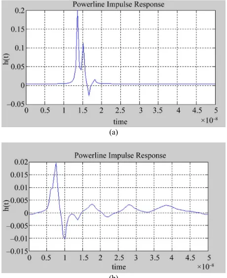
The power line communication channel exhibits multi-path propagation phenomenon. This is due to multiple lines with different characteristic impedances that are connected to the electrical network. Therefore, in this paper, the PLC channel is modeled as the multipath channel proposed in [4]. Power line channel exhibits dif-ferent types of noises including narrowband noise, co- lored noise, white Gaussian noise and also impulsive noise. According to [4], the frequency domain channel transfer function can be described as
0 1 di
e( 2j πf d vi P
1
k
N
a a f i
i
H f g e
(1)(b)
Figure 1. (a) Impulse respon where gi is the weighting factor for the i
th path, 0 1 are attenuation factors, k is the exponent of the attenuation factor, N is the number of paths, di is the length of the ith path, and vp is the propagation velocity of the cable.
a a,
0, 2
N k
Figures 1(a) and (b) show the impulse responses for 4-path and 15-path PLC channels respectively. Higher number of multiple paths contributes to higher signal dis- tortion.
2.2. Noise Model
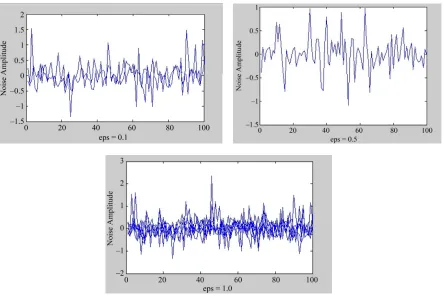
The indoor power line channel is a time-varying fre-quency selective fading channel with interference due to the colored and impulsive noise generated by electrical appliances and external sources. Multipath response due to the power cable layout and loading conditions is also a problem. Nevertheless, the worst signal impairment is due to the short duration and high peak impulsive noise. To model the noise in PLC, we use a Gaussian mixture model .The probability density function (PDF) of the impulsive noise can be described as
1
0, 2
f N (2)
where
se for 4-path PLC channel; (b) Impulse response for 15-path PLC channel.
is depicted in Figure 2. It can be clearly seen that the signal becomes highly impulsive when is equals to 1. Therefore a careful study is needed to reduce the impact of impulsive noise on the transmitted signal.
2.3. PLC Transmission System
ubcarriers and each The MC-CDMA system employs N s
user transmit M bits during a signaling interval, leading to the spreading factor or processing gain, G, of N/M. Figure 3 shows the structure of the transmitter. The user data stream, u is converted into M parallel streams and each stream is spread with the aid of orthogonal spread-ing sequences (e.g., Walsh Hadamard codes) which maps the same bit to G subcarriers. The spacing between the subcarriers conveying the same bit is set to M to reduce the correlation of the fading of these subcarriers. For simplicity, only single user is depicted in Figure 4, but a maximum of G users can be incorporated. The uth user’s spreading sequence, u
g
c , g0,1, 2G1, is orthogo-nal to other users’ spread model, each user transmits its data at the rate of M/T bps, where T is the frame duration. If the transmission rate can be low-ered, the maximum number of users, U, can be increased such that the data generated by the M users replace the 1: M serial-to-parallel converter. In this case, the total number of users supported can reach the total number of
ing code. In this
subcarriers, yielding U = N.
represents the probability of impulse occur-rence,
0, 2
N is the Gaussian noise component with zero mean and variance 2, and N
0,k2
is the im-pulsive noise component with zero mean and variance2
[image:2.595.308.538.85.367.2]
Figure 2. Noise amplitude plot for Gaussian mixture model for ε = 0.1, 0.5, and 1.0.
Figure 3. MC-CDMA transmitter structure.
The complex baseband representati d signal, X(t) can be expressed as:
on of the transmit-te
U 1M 1G 1 2π1 0 0 0
j gM m t
u c m
X t E b c
u Tg
u m g
e
(3)
where
U is the number of users, which has a maximum of G; the number of bits transmitted per user;
as
nsmitted and 1/T is equal to the spac-ing between adjacent subcarriers;
bits per user are tra
1 ubm is the mth bit of user u;
1
u g
c is the gth chip of the uth user’s spreading sequence.
Pilot symbols and cyclic prefix are then added to the
baseband si transmitted through
the PLC ch
the removal of the cyclic prefix. The received ve
gnal. This signal is then
annel. The demodulation at the receiver is done after
M is
G is the spreading factor or the processing gain given
ctor can be represented by
Y Xhn (4)
1
TY y a y a y L (5) N/M, where N is the number of subcarriers;
Ec is the energy per subcarrier, or chip, and Ec = Eb/N, where Eb is the energy per bit before spreading;
[image:3.595.100.497.406.545.2]Figure 4. Performance evaluation of conventional least square and proposed method.
1 1
1 1
x
x L a
1 2
T a
h h (7)
Tn L
(8)
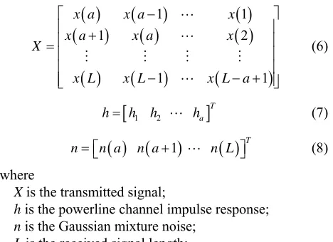
X is the transmitted signal;
h is the powerline channel impulse response; n is the Gaussian mixture noise;
L is the received signal length;
hannel impulse response length.
3.
L
Th e PLC chan-
itting some pilot symbols as bol-assisted schemes obtain te on the basis of known time e interspersed with the trans-
ixture
no e estimate
of the unknown channel is
x a x a
x L x L
1 2
x a x a x
X
(6)
h h
1n n a n a
where
a is the c
Channel Estimation
east Square Method
e estimation of the impulse response of th nel is carried out by transm
shown in Figure 5. Pilot sym a transfer function estima domain pilot symbols that ar
mitted data symbols. For each received pilot subcarrier the corresponding channel transfer function value is es- timated as the quotient of the received and the expected subcarrier value.
The received signal vector can be written as
P p
Y X hn (9)
where Xp denotes the transmitted pilot symbols, h and n denote the channel impulse response and gaussian m
[image:4.595.311.537.87.132.2]ise respectively. The conventional least squar
Figure 5. Channel estimation with pilot symbol insertion.
1H H
p p
p p
h X X X Y (10)
If Xp≥ a, the lease square estimate of the channel im pulse response is given by (Substitute Y = X × h + n into
-p p 10)) (
1 H H p p p p ph X X X X h n
From Equation (11) the additional 1
p
1 1 1 )H H H H
p
p p p X h p p p
h X X X X X X n
h h X n
(11)
X n term is actu-ally the frequency response of the noise component and may be expressed as
1
p
v X n (12)
Vector v is a sufficient statistics to calculate the
fre-qu n pil
ive components, by definition v can preserve the sparse property of
tions
ency response of the impulse noise o ot subcarriers, and thus its impact to the channel estimate. If Xp is larger than the noise impuls
f, that is, only few posi-will have large values dominated by the impulsive components, while other positions will have smaller value corresponding to Gaussian noise components.
Now we can rewrite (11) as
h h v (13) It is clear that the perfect channel impulse response is obstructed by the second term v. The main objective is to estimate the unknown v, and mitigate the impact of the
im impulse response by
can-celling the second part, v.
p p h
p
in sive noise component can super-
sede the Gaussian noise component po
pulse noise on the channel
The unknown v can be estimated by first calculating the difference between the received signals at Xp pilot sub-carriers and the recovered signal form h. The difference
ˆ
n can be expressed as
ˆnY X (14) The value of ˆn is depends on interference. The Gaussian noise component in ˆn are very sensitive to interference from impulsive noise com onents, since the
terference from impul
due to the large wer difference between them.
[image:4.595.57.291.305.475.2]nt. p
which can effectively tear apart impulsive noise compo-nent and Gaussian noise compone
Finally we cancel the im act of the estimated impulse noise component on h to get the new channel estimate:
1p
h h X n (1 ) where,
5
h is the estimated channel impulse response obtained with the proposed method.
Based on Equation (15), h is the newly estimated channel impulse response with minimum impact from impulsive noise component.
Th
significant improvement in ve plot. The proposed method gives im out 6 dB to the BER curve.
. doi:10.1109/MCOM.2003.1200105
4. Results
e simulation is carried out by transmitting 100 sym-bols in 64 subcarriers. The size of pilot symbol is 100 bits with a cyclic prefix of 25%. The obtained BER curve is plotted in Figure 4. The is
the BER cur provement ab
-5. Conclusion
In this paper, an MC-CDMA transmission system with proposed channel estimation at the receiver is more ro-bust against the impulsive noise existing in the power line channel.
REFERENCES
[1] S. Galli, A. Scaglione and K. Dostert, “Broadband Is Power: Internet Access through the Power Line Net-work,” IEEE Communications Magazine, Vol. 41, No. 5, 2003, pp. 82-83
onal
ommunications and Its Applications,
o. 4, 2002, pp. 553-559.
[2] S. Galli, K. Kerpez, S. Ungar and D. Waring, “Home Networks and Internet Appliances Shape Service Provider Access Architectures,” Proceeding of the Internati Symposium on Services and Local Access, Stockholm,
18-23 June 2000.
[3] H. Philipps, “Modeling of Power Line Communications Channels,” Proceeding of IEEE International Symposium on Power Line C
Lancaster, April 1999.
[4] M. Zimmermann and K. Dostert, “A Multipath Model for the Power Line Channel,” IEEE Transactions on Com-munications, Vol. 50, N
doi:10.1109/26.996069
[5] H. Philipps, “Development of a Statistical Model for Power Line Communications Channels,” Procee IEEE International Sym
ding of posium on Power Line
Commu- om-nications and Its Applications, Limerick, April 2000.
[6] M. Zimmermann and K. Dostert, “Analysis and Modeling of Impulsive Noise in Broad-Band Powerline Communi-cations,” IEEE Transactions on Electromagnetic C patibility, Vol. 44, No. 1, 2002, pp. 249-258.
doi:10.1109/15.990732
[7] L. Sanguinetti and M. Morelli, “Channel Acquisition and Tracking for MC-CDMA Uplink Transmissi
Transactions on Vehicu
on,” IEEE lar Technology, Vol. 55, No. 3,
2006, pp. 956-967. doi:10.1109/TVT.2005.863354 [8] L. Sanguinetti, I. Cosovic and M. Morelli, “Channel Esti-
mation for MC-CDMA Uplink Transmissions with Com-bined Equalization,” IEEE Journal on Selected Areas in Communications, Vol. 24, No. 6, 2006, pp. 1167-1178.
doi:10.1109/JSAC.2005.864023
[9] Y. Li, N. Seshadri and S. Ariyavisitakul, “Channel Esti-mation for OFDM Systems with Transmitter Diversity in Mobile Wireless Channels,” IEEE Journal on Selected Areas in Communications, Vol. 17, No. 3, 1999, pp. 461-