ISSN 2348 – 7968
Experimental Analysis of Brink Depth in a Smooth Rectangular
Channel
Sonali Swetapadma1, Dr. S. K. Mittal2, Prof. M.K. Choudhary3
1 M.Tech Student, Department of Civil Engineering, MANIT, Bhopal, M.P. India 2 Professor in Department of Civil Engineering, MANIT, Bhopal, M.P. India 3 Associate Professor in Department of Civil Engineering, MANIT, Bhopal, M.P. India
Abstract
In this paper, an experimental study showing the effects of slope on various characteristics of free over fall section in a smooth rectangular channel has been described. The experiment was conducted in horizontal and four different bed slope conditions. Variation of End depth ratio (EDR) with relative slope has been analyzed graphically. An empirical equation is proposed to estimate discharge in the channel by knowing the value of bed slope and brink depth or end depth. Depth of flow at different section is plotted graphically to analyze the variation in surface profile for different flow conditions. The effect of shear force near the over fall section is investigated graphically in terms of coefficient of skin friction.
Keywords: Free overfall, Brink depth, End depth ratio, Relative slope, Coefficient of skin friction.
1.
Introduction
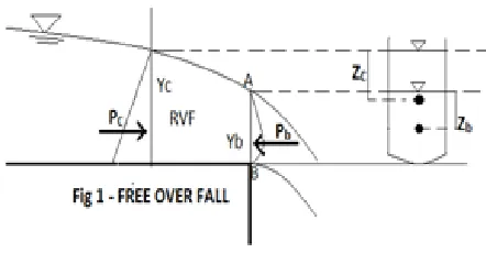
An open channel flow is a type of flow condition in which, water flows with a free surface exposed to atmosphere. In open channel flow, a sudden drop in the channel bed is known as Free over fall which is shown in the figure 1. The depth of flow at the free over fall section is known as ‘Brink depth’ or ‘End depth’. The flow profile changes from uniform flow to gradually varied and finally rapidly varied when it approaches the fall section. At the fall, the flow gets separated from the bed of the channel and falls freely under the action of gravity by forming a nappe. So the flow becomes rapidly varied near the end section with an appreciable curvature of streamlines.
At the end section, points A and B are exposed to atmosphere, so the pressure distribution is not hydrostatic there. Nearly parabolic pressure distribution can be
assumed at the fall section with zero pressure at points A and B, while hydrostatic pressure distribution can be assumed at the upstream critical section as the curvature of the water surface at the section A is very small. A control section is defined as a section at which a fixed relationship between the depth of flow and discharge exists. In general, the critical section at which critical depth of flow exists, acts as a control section. But in present case of free fall, the section at free overfall can be taken as control section as discharge-depth relation can be developed there.
Therefore, the computation of end depth and its analysis has gained more practical importance. Several experimental and analytical works have been carried out till date on brink depth in different shapes of channel. No attempt was made by any investigator to analyze shear force variation at the free over fall section. Knowledge of shear force is an important factor in the analysis of open channel flow due to the following reasons.
Fig. 1 Schematic Representation of Free over fall section
For the design of channel in non coherent alluvium
To prevent sediment laden flow in open channel by keeping the bed shear stress more than the critical shear stress
ISSN 2348 – 7968 Hunter Rouse (1956) was the first one to investigate in this
field and concluded the end depth ratio as 0.715 for mildly sloping rectangular channel. After him a lot of works have been carried out in different shapes of open channel to study the effect of slope and roughness. Diskin (1961), Rajaratnam (1962), Replogle (1962) applied various
theoretical model to develop equations for EDR.Davis et al. (1998) carried out an experimental study of the free overfall from a rectangular channel for various slopes and bed roughness. Two empirical equations were proposed for calculating this relationship, the first requiring only the data of channel slope and the second requiring both channel slope and roughness data. Tigrek et al. (2008) carried out an experimental study to get a relationship between brink depth and discharge at a rectangular free over fall. They derived equations for end depth ratio and discharge. Mohammed et al. (2011) carried out an
experimental study to determine the effect of gravel roughness and channel slope on rectangular free over fall.
2. Experimental set up and procedure
2.1 Laboratory set up
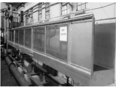
The experimental work was carried out in Hydraulics laboratory of Civil engineering department, MANIT, Bhopal. The rectangular channel as shown below was 9.45m long, 60cm width and 60cm depth. The side walls were made of glass fitted. The whole channel was resting on three points. There was a gear arrangement to tilt the channel at required slopes. Two to three perforated steel sieves were welded at the entrance section to achieve steady flow early. Water was supplied by a centrifugal pump (20hp motor) and a venturimeter was there for discharge measurement (inlet diameter = 6’’, throat diameter=3’’). A moving pointer gauge arrangement was provided to measure the depth of flow at different sections.
2.2 Procedure
The experiment was carried out for smooth bed surface of the channel, with horizontal and four different slope conditions (1 in 425.5, 1 in 283.67, 1 in 170.2 and 1 in 121.5). Digital theodolite was used to make the channel bed horizontal and sloping. For each channel condition further discharge was varied three times by adjusting the opening valve. The following data were measured for each flow condition.
Fig. 2 Laboratory Set up
Discharge measurement by area velocity method using a Preston-Pitot tube
Surface profile by moving point gauge along the centre line
Preston-Pitot tube reading at the bed level to calculate bed shear stress
End depth measurement
Discharge Calculation - For all flow conditions,
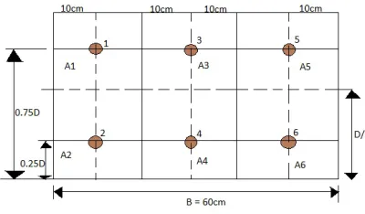
discharge was measured by selecting a section on upstream side and measuring the velocity of flow by means of Prandlt-Pitot tube at six different points (Fig 3) on that section.
V = Cv × 2 , (1)
Where, Coefficient of velocity (Cv) = 0.98 and h is the differential manometer reading. The discharge was measured as
Q =∑ , (2)
where Qi is the discharge measured at one point i.e. = AiVi.
Critical depth – From discharge, critical depth for
rectangular channel was calculated by using following expression which is based on critical energy concept.
YC= ∗ )1/3 , (3)
ISSN 2348 – 7968
Fig. 3 Selection of points for discharge calculation
Critical slope – Critical slope was calculated using
Manning’s resistance equation, in which critical depth of flow (YC) is used in place of normal depth of flow (Yo).
SC = (Q2n2P4/3) / A10/3, (4)
where n is Manning’s roughness coefficient and P is the wetted perimeter.
Surface profile - After marking the critical section, depth
of flow was measured by means of the moving pointer gauge arrangement along the center line of the channel to plot surface profile. End depth at the fall section was measured manually as it was not possible to use pointer gauge there.
Shear stress - For estimating the bed shear stress,
Prandlt-Pitot tube reading was also taken while keeping the Prandlt-Pitot tube at the channel bed along the center line. The following formula (Patel, 1965) was used for shear stress calculation. According to which non dimensional parameters X* and Y* are given as,
X* = log [{∆Pd d2} / {4ρV2}]
Y* = log [{τ0d2} / {4ρV2}]
Where Y* = 0.5X* + 0.37; for X*<2.9
Y* = 0.8287 - 0.1381X* + 0.1437X*2 - 0.006X*3; for 2.9<X*<5.6
X* = Y* + 2log (1.95Y*+4.10); for 5.6<X*<7.6 (5)
Where ∆Pd is the dynamic pressure head measures using U- tube differential manometer (inclined), d is the outer
diameter of Preston tube, V is the flow velocity and τ0 is the bed shear stress
Coefficient of skin friction – After estimating the bed
shear stress, coefficient of skin friction is calculated as follows.
cf = τ0 / ( )ρVC2, (6)
where VC is the critical velocity of flow, which can be estimated through following expression.
Vc = Q/ (B*Yc)
3.
Results and Discussion
For each flow and channel alignment condition data obtained were used to estimate critical depth of flow, EDR (end depth ratio= ) and relative slope ( ) as given in (Appendix 1).
The relationship between EDR and relative slope is shown in Fig 4. From the graph, it is concluded that end depth ratio ( ) gradually decreases with increase in relative bed
slope ( ). This relationship can be expressed by the following equation of best fit straight line with R2 = 0.968,
Ye/Yc = -0.240*( ) + 0.725 (7)
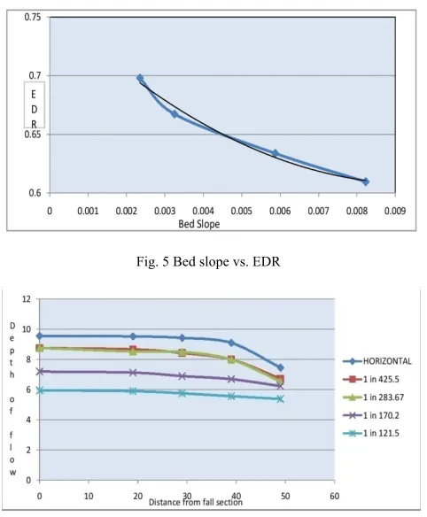
As the free over fall section acts as a control point, where the end depth or brink depth is used for discharge estimation; here a Fig 5 is plotted between bed slope and end depth ratio. A best fit quadratic equation was determined to develop relationship between bed slopes (So) and end depth ratio (Ye/Yc). The quadratic equation (Correlation coefficient R2 = 0.983) is given by,
Ye/Yc = 1653So2 – 31.63So + 0.759 (8) From equation (7),
Ye/Yc = φ1 (So)
Yc = φ2 (q), from equation (3).
The above two relationship can be summarized as below,
Total discharge in the channel
ISSN 2348 – 7968 Where φ(So) = (φ1 (So))3 , Ye is the end depth or brink
depth and B is the total width of the channel.
So from equation (9), if bed slope and brink depth are known, related discharge can be calculated directly.
Fig. 4 Relative slope vs. EDR
By measuring the depth of flow of water at different section, surface profile is plotted for each channel condition as shown in Fig 6. As the slope of the channel becomes steeper, depth of flow gradually decreases and falter surface profile is obtained as compare to horizontal and other flat slopes.
Fig. 5 Bed slope vs. EDR
Fig. 6 Surface Profile
To analyze the variation of shear force, a graph is plotted between average of local skin friction coefficient (cf) and distance of the section from free over fall as shown in Fig (7). As we approaches towards the free over fall section, local shear force increases and so as the value of cf. For each alignment of channel bed, variation of coefficient of skin friction with a non dimensional parameter (X/Yc) for each flow condition is given in Appendix 2. By knowing
the shear force, it can be included in the momentum equation for the calculation of brink depth or end depth.
Fig. 7 Average cf vs. Distance
4.
Conclusions
This paper describes the effect of slope on free over fall in a smooth rectangular channel. Various aspects of brink depth at free over fall section, such as discharge-depth correlation, surface profile, shear force variation have been analyzed graphically.
It is concluded that slope affects the end depth or brink depth, since as the bed slope increases end depth ratio gradually decreases.
Knowledge of brink depth and bed slope can be used to estimate the discharge in the channel as given in equation (9).
Surface profile is also affected by bed slope, as slope increase, surface profile becomes flatter.
As we approaches towards the fall section, shear force increases and there by the value of cf, as shown in Appendix 2. As the slope becomes steeper, value of cf decrease because horizontal component of weight balances the bed shear force in case of steep channel.
References
ISSN 2348 – 7968
WITH RECTANGULAR FREE OVERFALL” Journal of Hydraulic Engineeirng ASCE, 124:760-763, 1998.
[2] Amirabdollahian M., Farshi F. and Kabiri-Samani A.,” ESTIMATING FLOW PROPERTIES OVER FREE OVER FALL USING CONFORMAL MAPPING” 9th International Congress on Civil Engineering May 8-10, Isfahan University of Technology, 2012.
[3] Ahmad Z.,”QUASI THEORETICAL END DEPTH DISCHARGE RELATIONSHIP FOR RECTANGULAR CHANNELS” Journal Of Irrigation and Drainage Engineering, ASCE, 129:138-141, April 2013.
[4] BEIRAMI M.K., NABAVIS. V. and CHAMANI M. R. “FREE OVERFALL IN CHANNELS WITH DIFFERENT CROSS SECTIONS AND SUB-CRITICAL FLOW” Iranian Journal of Science & Technology, Transaction B, Engineering, Vol. 30, No. B1, 2006.
[5] Davis A. C., Ellett B. G. S., and Jacob R.P.,” FLOW MEASUREMENT IN SLOPING CHANNELS WITH RECTANGULAR FREE OVERFAL”, J. Hydraulic Eng., ASCE, 124:760-763,1998.
[6] Delleur, J.W., Dodge, J.C.I and Gent, K.W., “INFLUENCE OF SLOPE AND ROUGHNESS ON THE FREE OVER FALL”, Journal of Hydraulic Engineering, ASCE, 82(HYR), 1956.
[7] Dey, S., “END DEPTH IN STEEPLY SLOPING ROUGH RECTANGULAR CHANNELS”, Sadhana, Vol. 25, Part 1, pp. 1- 10, February 2000.
[8] Ferro, V., “FLOW MEASUREMENT WITH RECTANGULAR FREE OVERFALL”, Journal of Irrigation and Drainage Engineering, ASCE, 118:956-964, 1992.
[9] Ferro, V., “THEORITICAL END DEPTH DISCHARGE RELATIONSHIP FOR FREE OVER FALL” Journal of Irrigation and Drainage Engineering, ASCE, 125:40-44, February 1999.
[10] Guo, Y., “NUMERICAL MODELLING OF FREE OVERFALL”, Journal of Hydraulic Engineering, ASCE, 131:134-138, 2005.
[11] Guo, Y., Zhang, L., Shen, Y. and Zhang, J., “MODELLING STUDY OF FREE OVERFALL IN A RECTANGULAR CHANNEL WITH STRIP ROUGHNESS”, Journal of Hydraulic Engineering, ASCE, 134:664-667, 2008. [12] Hou, Q., Zhang, L. , Tijsseling, A.S. , Kruisbrink, A.C.H., “SPH SIMULATION OF FREE OVERFALL IN OPEN CHANNELS WITH EVEN AND UNEVEN BOTTOM ” Centre for Analysis, Scientific computing and Applications Department of Mathematics and Computer Science Eindhoven University of Technology, 2013
[13] Jain, A.K., Fluid Mechanics, New Delhi: Khanna Publishers, 2012.
[14] Mittal S. and Desmukh T., “FLOW ESTIMATION IN RECTANGULAR AND TRAINGULAR FREE OVERFALLS”, Journal of M.A.C.T, Volume 31, October 1998.
[15] Mittal S., Desmukh T. and Gupta P., “END DEPTH IN EXPONENTIAL CHANNELS”, Dept. Of Civil Engg. , M.A.C.T. Bhopal.
[16] Mohammed, A. Y., “EFFECTOF BED ROUGHNESS DISTRIBUTION AND CHANNEL SLOPE ON RECTANGULAR FREE OVERFALL”, The 10th Int. Conf. on Hydro science and Engineering, Nov. 4 – Nov. 7 2011, Orlando, USA.
[17] Mohammed M. Y., Ahmed Y. Al-taee and Al-Talib Azza N., “GRAVEL ROUGHNESS AND CHANNEL SLOPE EFFECTS ON RECTANGULAR FREE OVERFALL” Damascus University Journal Vol. (27) - No. (1), 2011.
[18] Mohammed A. Y.,”EFFECT OF BED ROUGHNESS DISTRIBUTION AND CHANNEL SLOPE ON RECTANGULAR FREE OVERFALL” AL-Qadisiya Journal For Engineering Sciences ,Vol. 6.No 2, 2013.
[19] Rouse, H., “DISCHARGE CHARCTESTICS OF FREE OVERFALL”, Civil Engg. ASCE, April 1936.
[20] Rajaratnam, N., Muralidhar, D. and Beltaos, S., “ROUGHNESS EFFECTS ON RECTANGULAR FREE OVER FALL”, Journal of Hydraulic Engineering, ASCE, August 1976. [21] Rai, A.S., “END DEPTH AT A DROP IN RECTANGULAR CHANNELS”, M.E. Thesis, Civil.
[22] Subramanya, K. and Keshavamurthy, K., “FLOW IN OPEN CHANNELS”, Tata McGraw-Hill Publishing Co., New Delhi, 1989
[23] Subramanya, K. and Keshavamurthy, K., “FLOW IN OPEN CHANNELS”, Tata McGraw-Hill Publishing Co., New Delhi, 1989.
[24] Tiwari H., “END DEPTH COMPUTATIONS IN PRISMATIC CHANNELS”, M.Tech Thesis, Dept. Of Civil Engg. MANIT, Bhopal, 1994
[25] Tigrek S., Firat C. E. and Ger A. M., “USE OF BRINK DEPTH IN DISCHARGE MEASUREMENT”, Journal of Irrigation and Drainage Engineering ASCE, 134:89-95, 2008. [26] Zachoval Z., Bohm P., Parilkova J., Safar R. and Sulc J. “SHAPE OF THE NAPPE DURING FREE OVERFALL FROM A RECTANGULAR CHANNEL WITH ZERO BED SLOPE”J. Hydrology Hydromechanics, 61, 2013, 3, 222–231, 2013
First Author Sonali Swetapadma has obtained her B.Tech degree in
Civil Engineering (2013) from VSSUT, Burla. Presently she is pursuing M.Tech in Water Resource Engineering at MANIT, Bhopal. She has published two papers; one in an international journal (IJER) and another in international conference (CSM). Her current Research of interest is hydraulics and water resource engineering.
Second Author Prof. S. K. Mittal is working as a professor in Civil
Engineering department of MANIT, Bhopal. He has published nearly 93 papers in international journals and conferences. His major area of research is hydraulics, irrigation and water resource engineering
Third Author Prof. M. K. Choudhary is working as Associate professor
in Civil engineering department of MANIT, Bhopal. He has published nearly 20 research papers in international journals and conferences. His
ISSN 2348 – 7968
.
APPENDIX 1