Eleven Level Cascaded Symmetrical Inverter for Grid
Connected System
R.KUMARA SWAMY Assistant Professor
Department of Electrical & Electronics Engineering,
Narsimha Reddy Engineering College, Maisammaguda;
Rangareddy (Dt); Telangana, India. Email:[email protected]
Y.NAGENDRA Assist Professor Department of Electrical & Electronics
Engineering,
Narsimha Reddy Engineering College, Maisammaguda;
Rangareddy (Dt); Telangana, India. Email:[email protected]
M.SRINIVAS M.Tech Student Scholar Department of Electrical &
ElectronicsEngineering, Narsimha Reddy Engineering
College,Maisammaguda; Rangareddy (Dt); Telangana, India. E:[email protected]
Abstract: Multilevel inverter has emerged recently as a very important alternative in the area of high-power medium voltage energy control. This project present cascaded multi cell with separate DC sources. Multilevel inverters are promising they have nearly sinusoidal output-voltage waveforms, output with better harmonic profile, less stressing of electronic components. The conventional is a single-phase eleven level inverter for grid connected photovoltaic systems, with a novel pulse width-modulated (PWM) control scheme .In a conventional concept to get the eleven level inverter output voltage using a four full bridge cascaded type inverter. The inverter is capable of producing eleven levels of output-voltage levels from the dc supply output-voltage. The proposed inverter system is capable of producing eleven level of output voltage levels dc supply voltage by using five full bridge cascaded topology type inverter. In this project has used to three H-bridge inverter with different dc sources. The multi-level inverters promising the high performance with reduced EMI and harmonics. The proposed project is eleven-level inverter was designed and results were also shown in the thesis. This project is focused on minimizing the number of semiconductors devices for a given number of levels.The proposed concept can be implemented to eleven level symmetrical cascaded multi level inverter for grid connected system by using Matlab/Simulink software.
Keywords-Multi level inverter; SPWM; harmonic
analysis; power electronics;
I. INTRODUCTION
Since past few year power consumers like industrial and commercial consumers face numerous power quality problems. Among them are harmonics and unbalances which are of great interest. Voltage quality get deteriorate with tremendous increase of nonlinear loads connected at distribution level. The primary target of connected generation is to guarantee grid-connected current with the same frequency and phase with grid voltage with the minimal total harmonic distortion (THD)[1-2]. In recent years, the multilevel voltage inverter has received wide attention in research and high-power applications such as large induction motor drives, UPS systems and flexible AC transmission systems and single phase grid connected
systems. As compared to traditional two-level inverters, the multilevel inverters have more advantages, such as lower semiconductor voltage stress, better harmonic performance, low electromagnetic interference and lower switching losses[2].
The common topology of this inverter is full-bridge three level. The need of multilevel inverter is to give a high output power from medium voltage source like batteries, super capacitors, solar panel. Multilevel inverters are promising; they have nearly sinusoidal output voltage waveform. It also reduces the harmonics of output current. As compared to conventional two-level inverter multitwo-level inverter has less switching losses, less stress on electronic components due to decrease in voltage, a smaller filter size, and lower electromagnetic interference(EMI), all of which make them cheaper, lighter and more compact[4-6]. The multi level inverter consists of several switches. In the multi level inverter the arrangement switches angles are very important. To synchronies the inverter frequency with grid frequency closed loop control action is carried out[8-1O]. This paper presents the cascaded H-bridge multilevel inverters for single phase grid connected system and their effects on grid current. Any carrier based PWM is applicable for cascaded H-bridge (CHB). The working of CHB with phase shifted modulation is explained in this paper. The paper is organized as follows. Section II explains Cascaded H-bridge seven-level inverter. Section III explains the control strategy and Section IV presents the simulation results with harmonic analysis. Section V summarizes the result.
II. CASCADED H-BRIDGE MULTILEVEL INVERTER
CHB inverter is mainly determines by its operating voltage and the cost required for manufacturing. The CHB multilevel inverter requires a number of isolated dc supplies each of which feeds an H-bridge power cell [3]. The number of voltage levels in a CHB inverter can be found from
(1)
Where H is the number of cells per phase leg in H-bridge. For the CHB inverter, voltage level m is always an odd number while in other multilevel topologies like diode-clamped inverters it can have either an even or odd number of levels. Any carrier based PWM schemes can be used for CHB inverter. The carrier based modulation schemes for multilevel inverter can be classified in two categories as follows
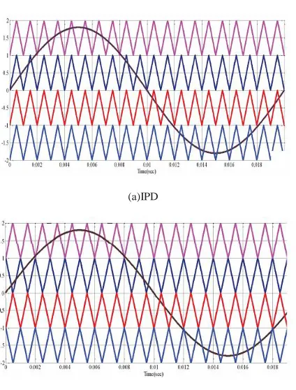
A. Level shifted multicarrier modulation The level shifted modulation scheme requires (m-I) triangular carriers for m level CHB inverter, all the carriers have the same frequency and the same amplitude. The (m-I) triangular carriers are vertically placed such that the bands forms by the carriers are contiguous. Following figure shows three schemes for the level shifted multicarrier modulation. (a) in-phase disposition (IPD), where all carriers are in phase; (b) alternative phase opposite disposition(APOD), where all carriers are alternatively in opposite disposition; and (c) phase opposite disposition(POD), where all carriers above the zero reference are in phase but in opposition with those below the zero reference.
(a)IPD
(b)APOD
(c)POD
Fig. I. Level shifted PWM The frequency modulation index is given by
(2)
Which remains the same as that for the phase shifted modulation scheme whereas the amplitude modulation
index is
defined as V,
(3)
Where Vm is peak amplitude of the modulating wave Vm and Vcr is the peak amplitude of each carrier wave.
B. Phase shifted multicarrier modulation In general, a multilevel inverter with m voltage levels requires (m-l) triangular carriers. In the phase shifted multicarrier modulation, all the triangular carriers have the same frequency and the same peak to peak amplitude, but there is a phase shift between any two adjacent carrier waves, given by
(4)
Fig. 2. Phase shift PWM for seven-level inverter
The principle of the phase-shifted modulation for a seven level CHB inverter is shown in fig. 2, where six triangular carriers are required with a 60° phase displacement (using equation (4)) between any two adjacent carriers. Modulating wave VMA is used. The carriers Veri, Vcr2, and Vcr3 are used to generate gatings for the upper switches QI, Qs, and Q9 in the left legs of power cells HI, H2 and H3 as shown in fig 3., respectively. The other three carriers, Vcrl-, Vcr2-, and Vcr3- , which are 1800 out of phase with Veri, Vcr2, and Vcr3, respectively, produce the gating for the upper switches Q2, Q6 and QIO in the right legs of the H- bridge cells. The gate signals for all the lower switches in the H-bridge legs are not shown since these switches operate in a complementary manner with respect to their corresponding switches [3]. The amplitude modulation index for phase shifted PWM as given in equation (5) is different than level shifted PWM. It does not depend on number of levels
(5)
TABLE I. SWITCHING TABLE
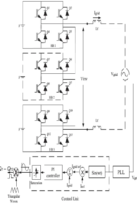
Fig. 3. Circuit diagram of Cascaded Seven level Inverter for single phase Grid Connected System
In this Phase locked loop (PLL) is used to synchronies the grid frequency with the supply frequency which makes the grid voltage and grid current are in phase with each other as shown in simulation result section. The Lf is the current limiting filter to limit the grid current. The current limiting inductor Lf is given by
(6)
with the reference current 19ridre/ The error from the comparison process of 19nd and Igridref was fed into the PI controller. The output of the PI controller, also known as Vref, being compared with the triangular wave to produce the switching signals for Q,-Q'2'.
IV MATLAB/SIMULINK RESULTS
Fig 4 Circuit diagram of Cascaded Seven level Inverter for single phase Grid Connected System
(a)
(b)
(c)
Fig, 5.(a) Three level Output voltage of inverter (b) In phase waveform of grid voltage and grid current (c)Harmonic Analysis of
Grid Current
(a)
(b)
(c)
Fig. 6,(a) Five level Output voltage of inverter (b) In phase waveform of grid voltage and grid current (c) Harmonic Analysis of Grid
Current
(a)
(c)
Fig 7(a) seven level Output voltage of inverter (b) In phase waveform of grid voltage and grid current (c) Harmonic Analysis of
Grid Current
Fig 8 Circuit diagram of Cascaded Eleven levels Inverter for single phase Grid Connected System
(a)
(b)
(c)
Fig 9 (a) nine level Output voltage of inverter (b) In phase waveform of grid voltage and grid current (c) Harmonic Analysis of Grid
Current
V. CONCLUSION
This paper presents the design and simulation of cascaded H-bridge seven level inverter for single phase grid connected system. Control strategy is carried out to synchronies the grid frequency with the inverter frequency and to generate the modulating wave to fire the switches of the inverter. The harmonic analysis of grid current is carried out for different levels. From the analysis it is clear that as the number of levels increases the %THD decreases. So multilevel inverter is used for grid connected system to inject less harmonic current to the grid.
REFERENCES
[1] N. A. Rahim, K. Chaniago, and l. Selvaraj, "Single-Phase Seven-Level Grid-Connected Inverter for Photovoltaic System, " IEEE Trans. Ind. Electron. , vol. 58,no. 6, pp. 2434-2443, June 20II.
[2] J. Rodriguez, l. Lai, and F. Z. Peng, "Multilevel Inverters: A Survey of Topologies, Controls, and Applications ", IEEE Trans. Ind. Electron., Vol. 49 , No. 4, pp. 724-738, August 2002,.
[3] Bim Wu, "Cascaded H-bridge Multilevel Inverter " in High power converters and Ac drives , New Jersey, pp.127-130.
[4] M. Mosa, H. A. Rub, M. Ahmed, A. Kouzou, J. rodriguez, " Control of single phase grid connected multilevel inverter using model Predective Control , " Int. Conf Power Eng, Energy and Electrical Drives, pp. 624- 628 , 2013
[5] McGrath, B.P.; Holmes, D.G.;, "Multicarrier PWM strategies for multilevel inverters , ", IEEE Trans. Ind. Electron, vo1.49, no.4, pp. 858- 867 , Aug 2002 [6] A. I. Maswood, Ooi H. P. Gabriel and E. Ammar, "Comparative study of multilevel inverters under unbalanced voltage in a single DC link, " lET Power Electron. Vol. 6 , Iss. 8, pp. 1530-1943,May.2013. [7] P. Palanivel and S.S. Dash, "Analysis of THO and output voltage performance for cascaded multilevel
inverter using carrier pulse width modulation
techniques, " lET Power Electron. Vol. 4, Iss. 8, pp. 95I-958, Mar.201I.
[8] F. Z. Peng, "A Generalized Multilevel Inverter Topology with Self Voltage Balancing, " IEEE Trans. Ind. Appl., voI.35, no.5, pp. 1098- 1107, Sep./Oct. 1999 [9] H. Wu, H. Sun, L. Cai, X. Tao, "Simulation on Control Strategies of Grid-connected Inverters , " IEEE Int. Sym. Power Electron. Distributed generation sys., pp. 904-908, 20I0
[1I] G. Carrara, S. Gardella, M. Marchesoni, R. Salutari and G. Sciutto, "A New Multilevel PWM Method: A Theoretical Analysis, " IEEE Trans. Power Electron., vol. 7,no.3,pp. 497-505, luI. 1992.
[12] D. N. Zmood and D. G. Holmes, "Stationary frame current regulation of PWM inverters with zero steady state error, " IEEE Trans. Power Electron. , vol. 18,no. 3, pp. 814-822,May 2003.
MARAPAKA SRINIVAS received B.tech from Avanthi’s Scientific Technological & Research Academy in the year of 2013 and M.Tech from Narsimha Reddy Engineering college. in the stream of Power Systems in the year of 2016.
R.KUMARA SWAMY received B.Tech degree from Balaji Institute of Technology and Science
(JNTUH) in the year 2011 and received M.Tech in the stream of Power Electronics at CMR College of Engineering
and Technology (JNTUH) in the year march 2014. Currently working as a Assistant Professor in Narsimha Reddy
Engineering College for Three years. And his areas of interest are Applications of Power electronics in “Power
Systems & Electrical machines”
Yadam Nagendra received B.Tech degree from Kandula Obul Reddy memorial College of