ISSN (Print) : 2320 – 3765 ISSN (Online): 2278 – 8875
I
nternational
J
ournal of
A
dvanced
R
esearch in
E
lectrical,
E
lectronics and
I
nstrumentation
E
ngineering
(An ISO 3297: 2007 Certified Organization)
Website: www.ijareeie.com
Vol. 6, Issue 7, July 2017
Comparative Study of Dispersion
Compensating Techniques Pre, Post and
Mix with 8 Channels
Ranjeet Kaur1, Gaurav Mittal2
M. Tech Student, Department of Electronics and Communication Engineering, BGIET, Sangrur, India 1
Assistant Professor, Department of Electronics and Communication Engineering, BGIET, Sangrur, India 2
ABSTRACT:Dispersion is the major factor to hamper long distance communication. To eliminate dispersion different compensation techniques are used, but among these dispersion compensation with DCF is most popular. DCF is used in three different compensation schemes. Quality factor and Bit error rate are analyzed at different fiber length. Dispersion Compensation Fiber has the negative and Single Mode Fiber has the positive Dispersion. These Schemes decrease dispersion and other non linearity effect as much extend. In optical Fiber communication, transmitters transmit optical information and at receivers side optical signal is converted back into electrical signal. Signal becomes distorted or week because of noise, dispersion and other nonlinearity effect. So sending signal over longer distance it is compulsory to suppressed dispersion. So dispersion compensation with Dispersion Compensation Fiber and Fiber Bragg Grating is the best scheme to reduce dispersion. In this paper we studied three different compensation techniques pre, post and mix compensation. It has been seen that mix compensation technique is best as compared to post and pre.
KEYWORDS: Dispersion compensation, Fiber brag grating, EDFA, BER, DCF, wavelength division multiplexing.
I.INTRODUCTION
ISSN (Print) : 2320 – 3765 ISSN (Online): 2278 – 8875
I
nternational
J
ournal of
A
dvanced
R
esearch in
E
lectrical,
E
lectronics and
I
nstrumentation
E
ngineering
(An ISO 3297: 2007 Certified Organization)
Website: www.ijareeie.com
Vol. 6, Issue 7, July 2017
II
.
LITERATURE SURVEYDispersion hampers both digital and analog transmission along optical fiber. Wavelength division multiplexing (WDM) technology combines a number of optical carrier signals into a single fiber with different wavelengths. WDM techniques increase the capacity and offer bidirectional communication. Fiber brag grating blocks certain wavelengths and passed wavelength having same phase. When the signal is send into the fiber, the distortion occurs because of dispersion and nonlinear effects of the fiber. So the distorted signal must be finished to keep the original signal. To decrease the signal distortion, the fibers must have opposite means positive and negative dispersion values. So we are using this topology so that dispersion can be eliminated suitably (3).
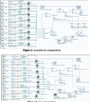
A Bessel filter is an analog linear filter which is same as Bessel– Thomson filters. When filter order increases it tends towards the shape of Gaussian filter. For dispersion compensation DCF was proposed in 1980 but when optical amplifiers are invented DCF helps to decrease the dispersion.SMF have positive and DCF have negative dispersion so total dispersion is zero. According to the position of DCF there are three compensation schemes pre compensation, post compensation and mix compensation.
In pre compensation scheme DCF is positioned before the SMF and post compensation Scheme DCF is positioned after the single mode fiber and in Mix compensation scheme DCF is positioned before and after the SMF (4)
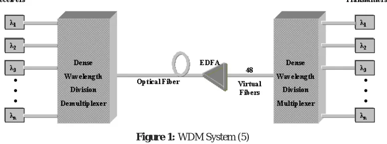
Fiber length depends upon the signal power, pump power and pump wavelength. Fig shows that input signal carrying wavelength 1550nm and the diode laser signal added by wavelength multiplexer. This signal passes through the EDFA where it get amplified and the we get amplified output signal .WDM combines multiple signals and send over a Single Channel and at Receiver side all channels are separated. (See fig. 1)
Figure 1: WDM System (5)
In 2013, authors proposed three different Dispersion compensation schemes according to the positions of DCF: i. Pre –compensation
ii.Post-Compensation iii.Mix-compensation
In pre-compensation scheme, the DCF is located before the standard single mode fiber (SSMF) to compensate the positive dispersion.
In post-compensation, the DCF is located after the SSMF to compensate the positive dispersion.
In Mix-compensation, both the schemes (pre-, post-compensation) are used i.e. DCF is located before and after the SSMF to get the dispersion (6).
III.PROPOSED METHODOLOGY
ISSN (Print) : 2320 – 3765 ISSN (Online): 2278 – 8875
I
nternational
J
ournal of
A
dvanced
R
esearch in
E
lectrical,
E
lectronics and
I
nstrumentation
E
ngineering
(An ISO 3297: 2007 Certified Organization)
Website: www.ijareeie.com
Vol. 6, Issue 7, July 2017
driver), laser source and Mach-Zehnder modulator. A pseudorandom sequence of bits is generated by data source at a rate of 10 Gbit/s modulator driver which produces NRZ format pulse with 0.5 duty cycle. Frequecny range is 193.1 to 193.8. Mach-Zehnder modulator have 30db Excitation ratio. One loop has been used. To completely compensate accumulated dispersion in the transmission fiber we have 150 km of SMF and 20 km of DCF. The total length of fiber channel is 170km. and two EDFA used before transmission fiber and DCF. At the receiver side, PIN diode which is used to change the optical signal into electrical signal. A low pass Bessel filter filters the noise. Dispersion is decresed in optical fiber by three dispersion compensation fiber (DCF) techniques. Figures and Tables are shown below
Figure 2: symmetrical compensation
ISSN (Print) : 2320 – 3765 ISSN (Online): 2278 – 8875
I
nternational
J
ournal of
A
dvanced
R
esearch in
E
lectrical,
E
lectronics and
I
nstrumentation
E
ngineering
(An ISO 3297: 2007 Certified Organization)
Website: www.ijareeie.com
Vol. 6, Issue 7, July 2017
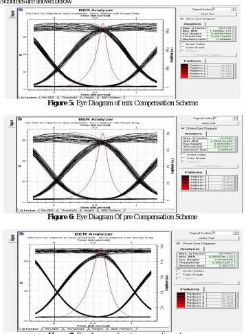
Figure 4: post compensation
Table 1: Fiber parameter
Simulation Parameters SMF DCF
Length(Km) 150 20
Attenuation(db/km) 0.2 0.6
Dispersion (ps/nm/km) 16 -80
Differential slope (ps/ 2 / ) 0.08 0.2
Differential group delay(ps/km) 0.5 0.5
PMD coefficient([ps/km) 0.5 0.5
Table 2: Simulation parameter
Parameter Value
Bit rate 10 Gb/s
Sequence length 128
Samples per bit 64
Central frequency of first channel 193.1
Channel spacing 100 Ghz
Capacity 8channel,10 Gb/s
Table 3: FBG Parameter
Parameters Value
Frequency(THz) 193.1
Effective index 1.45
Length of Grating 2 mm
Linear Parameter 0.0001um
Apodization function Uniform
Tanh parameter 0.5
Table 4: EDFA Parameter
IV. RESULT AND DISCUSSION
The results obtained by performing various experiments, as described in Section 3.Central frequency of laser is 193.1.different results are taken at constant fiber length and power. Eye diagrams of mix, pre and post
Mix pre Post
ISSN (Print) : 2320 – 3765 ISSN (Online): 2278 – 8875
I
nternational
J
ournal of
A
dvanced
R
esearch in
E
lectrical,
E
lectronics and
I
nstrumentation
E
ngineering
(An ISO 3297: 2007 Certified Organization)
Website: www.ijareeie.com
Vol. 6, Issue 7, July 2017
compensation schemes are shown below
Figure 5: Eye Diagram of mix Compensation Scheme
Figure 6: Eye Diagram Of pre Compensation Scheme
Figure 7: Eye diagram of post compensation scheme.
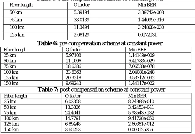
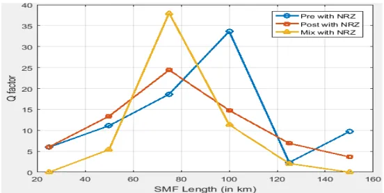
4.1Results Based on Different length of SMF at constant Power
ISSN (Print) : 2320 – 3765 ISSN (Online): 2278 – 8875
I
nternational
J
ournal of
A
dvanced
R
esearch in
E
lectrical,
E
lectronics and
I
nstrumentation
E
ngineering
(An ISO 3297: 2007 Certified Organization)
Website: www.ijareeie.com
Vol. 6, Issue 7, July 2017
Table 5: Mix compensation scheme at constant power
Fiber length Q factor Min BER
50 km 5.39194 3.39742e-008
75 km 38.0139 1.44099e-316
100 km 11.3494 3.24868e-030
125 km 2.08129 00172131
Table 6: pre compensation scheme at constant power
Fiber length Q factor Min BER
25 km 5.97108 1.14149e-009
50 km 11.1096 5.41783e-029
75 km 18.6386 7.06533e-078
100 km 33.6363 2.04081e-248
125 km 20.3218 3.53712e-092
150 km 9.69243 1.44117e-022
Table 7: post compensation scheme at constant power
Fiber length Q factor Min BER
25 km 6.02358 8.24988e-010
50 km 13.3826 3.42453e-041
75 km 24.4041 5.98543e-132
100 km 14.7791 9.41728e-050
125 km 6.89448 2.60351e-012
150 km 3.65253 0.000125256
4.2Results Based on Constant Fiber Length
Now we take different observation on different input power at constant length. In Mix compensation Length is 75 km and in pre compensation Length is 100 km and in post compensation Length is 75 km.
Table 8: Mix compensation scheme at constant fiber length
Input power(DB) Q factor Min BER
-21 5.78635 2.77244e-009
-17 9.08791 3.69177e-020
-13 13.0057 4.08025e-039
-9 16.853 3.62653e-064
-5 19.8575 3.50964e-088
-1 22.0575 3.03451e-108
0 22.3184 9.19407e-111
1 22.9122 1.32407e-116
5 24.5289 2.76632e-133
9 27.651 1.05831e-168
13 32.916 5.24343e-238
17 38.0139 1.44099e-316
ISSN (Print) : 2320 – 3765 ISSN (Online): 2278 – 8875
I
nternational
J
ournal of
A
dvanced
R
esearch in
E
lectrical,
E
lectronics and
I
nstrumentation
E
ngineering
(An ISO 3297: 2007 Certified Organization)
Website: www.ijareeie.com
Vol. 6, Issue 7, July 2017
Table 9: pre compensation scheme at constant fiber length
Input power(DB) Q factor Min BER
-21 7.00153 9.01346e-013
-17 11.4002 1.43884e-030
-13 17.2939 1.8646e-067
-9 24.221 5.09212e-130
-5 30.6445 1.25758e-206
-1 33.7929 1.03587e-250
0 33.6363 2.04081e-248
1 32.238 2.11446e-228
5 25.1718 3.13974e-140
9 18.6151 8.75545e-078
13 14.1752 4.50173e-046
17 10.2435 4.19073e-025
21 5.84367 1.58417e-009
Table 10: post compensation scheme at constant fiber length
Input power (DB) Q factor Min BER
-21 6.01786 6.30404e-010
-17 9.68637 1.18738e-022
-13 14.7944 5.61548e-050
-9 20.4092 5.15795e-093
-5 24.4708 1.17201e-132
-1 24.6573 1.19051e-134
0 24.4041 5.98543e-132
1 23.7708 2.57861e-125
5 19.9785 3.15618e-089
9 14.9947 2.84049e-051
13 9.09651 3.29017e-020
17 3.74889 6.80721e-005
21 1.76263 0.0329065
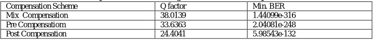
Results Comparison of Transmission Influence of three Compensation Schemes
Comparison among three compensation schemes and it observed that mix compensation scheme is best as compared to pre and post.
Table 11: Comparison Table among Three different compensation Schemes
Compensation Scheme Q factor Min. BER
Mix Compensation 38.0139 1.44099e-316
Pre Compensatiom 33.6363 2.04081e-248
ISSN (Print) : 2320 – 3765 ISSN (Online): 2278 – 8875
I
nternational
J
ournal of
A
dvanced
R
esearch in
E
lectrical,
E
lectronics and
I
nstrumentation
E
ngineering
(An ISO 3297: 2007 Certified Organization)
Website: www.ijareeie.com
Vol. 6, Issue 7, July 2017
Figure 8: Comparison of Transmission influence of three compensation scheme
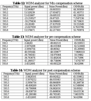
Table 12: WDM analyzer for Mix compensation scheme
Frequency(THz) Signal power (dbm) Noise Power(dbm) OSNR(db)
193.1 13.590407 -30.803553 44.393959
193.2 13.529239 -27.814472 41.343711
193.3 13.433687 -30.695331 44.129018
193.4 -23.218527 -30.47325 7.2547236
193.5 -18.279434 -36.998065 18.718631
193.6 -18.28349 -37.437039 19.153549
193.7 -23.827659 -30.591037 6.7633786
193.8 13.576671 -42.217303 55.793974
Table 13: WDM analyzer for pre compensation scheme
Frequency(THz) Signal power (dbm) Noise Power(dbm) OSNR(db)
193.1 -3.44261 -49.002121 45.559511
193.2 -3.5074208 -46.031064 42.523644
193.3 -3.5956754 -48.86562 45.269945
193.4 -40.591644 -48.559677 7.9680333
193.5 -36.784543 -54.979364 18.19482
193.6 -36.763674 -55.482634 18.71896
193.7 -41.280517 -48.754696 7.4741787
193.8 -3.4532691 -60.083229 56.62996
Table 14: WDM analyzer for post compensation scheme
Frequency(THz) Signal power (dbm) Noise Power(dbm) OSNR(db)
193.1 -3.4426101 -49.002422 45.559812
193.2 -3.5074212 -46.031043 42.523622
193.3 -3.5956716 -48.864409 45.268738
193.4 -40.408269 -48.563079 8.1548094
193.5 -36.790994 -54.882614 18.09162
193.6 -36.838718 -55.469854 18.631136
193.7 -41.280348 -48.745545 7.4651976
ISSN (Print) : 2320 – 3765 ISSN (Online): 2278 – 8875
I
nternational
J
ournal of
A
dvanced
R
esearch in
E
lectrical,
E
lectronics and
I
nstrumentation
E
ngineering
(An ISO 3297: 2007 Certified Organization)
Website: www.ijareeie.com
ISSN (Print) : 2320 – 3765 ISSN (Online): 2278 – 8875
I
nternational
J
ournal of
A
dvanced
R
esearch in
E
lectrical,
E
lectronics and
I
nstrumentation
E
ngineering
(An ISO 3297: 2007 Certified Organization)
Website: www.ijareeie.com
Vol. 6, Issue 7, July 2017
Figure 9: Input power and Min BER Of three compensation Schemes
ISSN (Print) : 2320 – 3765 ISSN (Online): 2278 – 8875
I
nternational
J
ournal of
A
dvanced
R
esearch in
E
lectrical,
E
lectronics and
I
nstrumentation
E
ngineering
(An ISO 3297: 2007 Certified Organization)
Website: www.ijareeie.com
Vol. 6, Issue 7, July 2017
Figure 11:Fiber Length and Min BER of three compensation Schemes
Figure 12: Input frequency and OSNR of three compensation Schemes
V.CONCLUSION
ISSN (Print) : 2320 – 3765 ISSN (Online): 2278 – 8875
I
nternational
J
ournal of
A
dvanced
R
esearch in
E
lectrical,
E
lectronics and
I
nstrumentation
E
ngineering
(An ISO 3297: 2007 Certified Organization)
Website: www.ijareeie.com
Vol. 6, Issue 7, July 2017
REFERENCES
[1]. Performance of backbone line Pristina-Skopje in 10 GBPS \& 40GBPS using WDM and EDFA Amplifier Technology. Limani, Besim. 2016, International Journal of Current Engineering and Technology.
[2]. Design Performance of High Speed Optical Fiber WDM System with Optimally Placed DCF for Dispersion Compensation. Yadav, Mulayam, et al. 20, s.l. : Foundation of Computer Science, 2015, International Journal of Computer Applications, Vol. 122.
[3].Dispersion Compensation with Dispersion Compensating Fibers (DCF). Kaur, Manpreet, Sarangal, Himali and Bagga, Parveen. 2015, International Journal of Advanced Research in Computer and Communication Engineering.
[4].Dispersion compensation using FBG and DCF in 120 Gbps WDM systems. Singh, Gagandeep, Saxena, Jyoti and Kaur, Gagandeep. 6, 2014, International Journal of Engineering Science and Innovative Technology (IJESIT), Vol. 3.
[5]. Performance Analysis of Dispersion Compensation in Long Haul Optical Fiber using DCF. Singh, Parul and Chahar, Rekha. 8, 2014, The International Journal Of Engineering And Science (IJES), Vol. 3.
[6]. Analysis on Dispersion Compensation of DWDM System with DCF and Various Modulation Formats. Singh, Sumit Pal and Kaur, Karamjit. 2013, International Journal Of scientific &Engineering Research.
[7]. Dispersion Compensation in 40 Gbps WDM Network Using Dispersion Compensating Fiber. Patel, Gaurang H., Patel, Rohit B. and Patel, Swetha J. 2, 2013, Journal of Information and Research in Electronics and Communication Engineering, Vol. 2.
[8]. Comparison of Pre-, Post-and Symmetrical-dispersion Compensation Schemes for 10/15 GBPS using Different Modulation Formats at Various Optical Power Levels using Standard and Dispersion Compensated Fibers. Pal, Raju and Sharma, Vishal. 21, s.l. : Foundation of Computer Science, 2012, International Journal of Computer Applications, Vol. 50.
[9].Various Dispersion Compensation Techniques for Optical System: A Survey. Kahlon, N. K. and Kaur, G. 1, 2014, Open Journal of Communications and Software, Vol. 1, pp. 64-73.