Microcontroller and SD Card Based
Standalone Data Logging System using SPI
and I2C Protocols for Industrial Application
M. B. Satheesh1, B. Senthilkumar1, T. Veeramanikandasamy2, O. M. Saravanakumar2
PG Student, Department of Electronics and Communication Systems, Sri Krishna Arts and Science College,
Coimbatore, Tamilnadu, India1
Assistant Professor, Department of Electronics and Communication Systems, Sri Krishna Arts and Science College,
Coimbatore, Tamilnadu, India2
ABSTRACT: The low cost micro SD card based Data Logging System (DLS) for the measurement of parameters such as temperature, load current, load voltage and power have been designed and developed. These parameters are the time varying signals that are sensed by respective sensors. The sensor values are read by on-chip ADC and it is used for further process. The micro secured digital (SD) card is interfaced with PIC18F45K22 microcontroller in Serial Peripheral Interface (SPI) mode of Master Synchronous Serial Port (MSSP) for DLS design. The RTC is also interfaced to the microcontroller using I2C protocol to provide time stamping. The designed DLS has been tested with the application program developed in MPLAB X IDE which can write data into SD card at the rate of 5 samples / second.
KEYWORDS: Data Logging System, Load current and voltage, PIC microcontroller, microSD card, SPI, RTC, I2C.
I. INTRODUCTION
The term ‘data logging’ can be defined as the capture and storage of data for use at a later time. Basically, a data logger is an electronic device that is capable of capturing and recording data overtime [1, 2]. Modern data loggers are based on the microcontroller technology which is usually portable, battery-operated devices with internal memory storage and some interfaced sensors to measure physical quantities such as temperature, pressure, flow, voltage and so on.
Data loggers can be categorized into two groups: standalone data loggers and data capturing data loggers. The data loggers that can work on their own are termed as standalone data logger. It does not depend on other external devices for data collection and storage. These data loggers have large amounts of internal non-volatile memories. They may also interfaced with real time clock chips. The collected data can be saved in the memory with time stamping [3, 4]. Once the data collection period is completed the device is connected to a PC and the logged data are read from memory device which helps PC in analyzing the values offline.
Data loggers that are used only to read the data are termed as data capturing data loggers. These devices do not store data into memory device and are normally connected with a PC for displaying or storing the data. Either the offline or online analyze can performed on the collected data. Data capturing data loggers have a disadvantage of requiring a supporting device like PC to store the captured data. In this work, we have designed the standalone data loggers with the help of PIC18F45K22 microcontroller.
II. MATERIALS AND METHODS
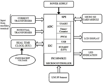
section, microSD card module, and a display device. The current and voltage signals are acquired from the load by using current and potential transformers. The on-chip ADC is interfaced with current and potential transformer to get the load current and load voltage from the machine. The ADC samples the current and voltage signals and converts into digital form. The digital values are given to MCU for the power factor analysis. The LM35 sensor is used to sense the current temperature at the machine. A microcontroller of PIC18F45K22 with a crystal of 20 MHz has been utilized in the proposed system. The MCU is updating the LCD display by the temperature, voltage, current and power factor information. The readings can also be transmitted to microSD card through SPI protocol for the regular period of time using RTC. The RTC is interfaced with MCU using I2C protocol.
Figure 1: Block diagram of standalone data logger using PIC Microcontroller
2.1 Power Supply
The 230V mains AC voltage is reduced to 12V AC with help of step down transformer. This AC voltage is converted into 5V DC using bridge rectifier and a 7805 type 5V regulator which can deliver current up to 1A.
2.2 Sensing Elements
2.2.1 Current Transformer (CT)
2.2.2 Potential Transformer (PT)
Potential transformer or Voltage transformers are also a metering device that are most commonly used to lower the high line voltages down to typically 120V or 12V or 5V [6]. This reduced voltage on the secondary side can be connected to analog to digital converter of PIC microcontroller.
2.2.3 Temperature Sensor
The temperature of the environment is measured using LM35 temperature sensor which is widely used in most of temperature sensing applications [7]. The sensor produces analog DC output voltage on its output terminal. It produces 10 mV for every degree centigrade of temperature. LM34 sensor is particularly used if we need temperature value in Fahrenheit.
2.3 Timing Module
Real Time Clock module is referred as RTC. It is an important integrated circuit or device that will keep the track of current time and date [8]. In data logging system, the RTC module is used to give the precise time of the system for which parameter values are displayed. RTC module communicates through the I2C bus of PIC microcontroller.
2.4 Display Circuit 2.4.1 Display Circuit
The Liquid Crystal Display (LCD) is a flat panel display that uses the light modulating properties of liquid crystals (LCs) to display a character. The 4x20 character LCD board is used in this system. It supports both 4-bit and 8-bit mode [9]. Only 7 lines needed to create 4-bit interface: 4 data lines (D0 – D3), three control lines (RS, R/W and E).
2.4.1 LED Indication
The LED indicator is used to give an indication to machine operator whenever the energy consuming and power factor of a machine is higher than prescribed value.
2.5 Memory Device
The SD card is a flash type memory which is designed to provide high capacity, non-volatile rewritable storage in a small size. The memory capacity and speed are increasing all the time. The specifications of different types of SD cards are shown in the Table 1. The SD cards are in three different sizes like standard SD, mini SD, and micro SD cards. Micro Secured Digital (microSD) cards are the most widely used memory cards in modern world due to its very small size and larger memory size. The functionality of SD card is based on MMC but it has an advantage over MMC because of having an optional encryption feature [10].
Table 1: Different types of memory card
A standard SD card can be interfaced in two modes like SD Bus mode and SPI Bus mode. In SD bus mode, all the pins of the SD card are required to have a communication with microcontroller unit. In SPI bus mode, a communication with microcontroller takes place with a chip select (CS), a clock line (CLK), Data in (MOSI) pin and Data out (MISO) pin. The following are the pin numbers of SD card
Positive : Pin 4 Ground : Pin 3 and 6 Chip select : Pin 1 Data in : Pin 2 Clock : Pin 5
Card Max Capacity (GB) Max Write Speed(MB/s) Max Read Speed (MB/s) Operating voltage (v) Pin count
MMC 4 52 52 3.3 7
Micro MMC 2 40 40 3.3 13
SD 4 150 150 3.3 9
miniSD 4 100 100 3.3 11
Data out : Pin 7
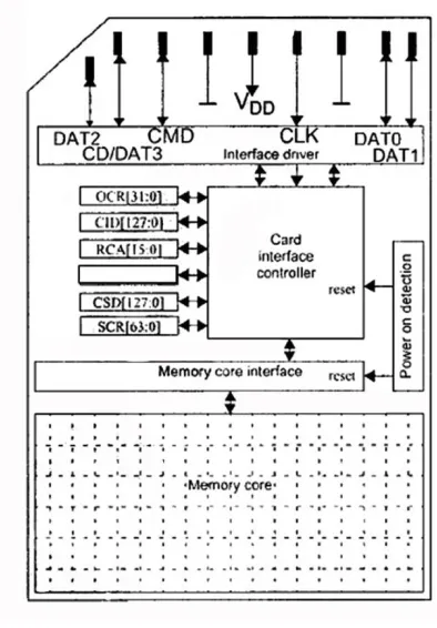
The architecture of SD card is shown in figure 2. The microSD card has been formatted as FAT32 before interfacing with MCU. The SD card only accepts the standard SD commands. Using these commands a MCU can read the SD card registers, and also read/write the memory core [11]. The most commonly used interfacing technique of SD card is SPI interfacing method. For the transferring of data in SPI mode a Data in pin, a clock pin, and a chip select line must be initialized. The card operates with 3.3V supply voltage and following are the maximum and minimum logic levels:
Maximum logic 0 output voltage, VOL = 0.4125 V Minimum required logic 1 input voltage, VIH = 2.0625 V Maximum logic 1 input voltage = 3.6 V
Maximum required logic 0 input voltage, VIL = 0.825 V.
Figure 2: SD Card Architecture
The maximum input logic of SD card is only up to 3.6V but the logic high of PIC microcontroller is 5V. So the voltage level should be reduced to the limit of SD card using potential divider or regulator IC’s. The output voltage 3.2V of SD card can be detected as logic 1 by PIC microcontroller as voltage above 0.8-5V is considered as logic high signal. SD cards can be interfaced to microcontrollers using two different protocols: The SD card protocol and the SPI protocol. In this system SD card is interfaced with microcontroller using SPI protocol. The data are stored into a microSD card as text file. The text file can be an existing one or a new one created by the user using developed application software.
2.6 PIC Microcontroller – The Central Unit
III. HARDWARE DESIGN
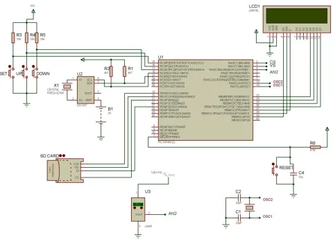
The circuit diagram of microcontroller and SD card based standalone data logging system using SPI and I2C protocol is shown in figure 3. The PORTA pins are made as analog input by using ADCON1 register. The PORTB pins are used to interface LCD display unit in 4-bit mode where the LSB (0-3) bits act as DATA lines and MSB (4-6) bits act as control lines. The MSSP1 module signal lines are multiplexed with PORTC pins and it is used to interface RTC module in I2C mode. The MSSP2 module lines are multiplexed with PORTD pins and it is used to interface the microSD card module in SPI mode. The LSB (0-2) three bits of PORTC are used to set time for RTC module according to the region.
Figure 3: Circuit diagram of microcontroller and SD card based standalone data logging system
IV. SOFTWARE DESIGN
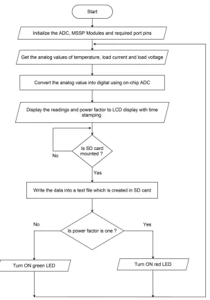
mounted to the module. If the microSD card is not mounted the program will not enter into data write operation. The current and voltage signal values are introduced in MCU from the load by using CT and PT. The microcontroller calculates the phase angle between current and voltage signals by measuring time interval using on-chip timer. Using power factor formula the MCU calculates the power factor. If the power factor is equal to one, the red LED is turned ON otherwise the green LED is ON.
Figure 4: Flowchart of standalone data logger using PIC Microcontroller
V. CONCLUSION
REFERENCES
[1] A. Purwadi, Y. Haroen, Farianza Yahya Ali, N. Heryana, “Prototype development of a Low Cost data logger for PV based LED Street Lighting System”, IEEE Conference Proceeding, pp.1-5, July 2011.
[2] Vandana, Wasim G. Madiwale, Nithin Awasthi, “An Efficient Data Logger System for Continuous Monitoring and Traceability of Cargo: Application of GPS and GSM Technology”, International Journal of Research in Engineering and Technology, Vol.03, pp.569-572, 2014. [3] G. L. Kooyman, “Techniques used in Measuring Diving Capacities of Weddell Seals”, Polar Record, Vol.12, pp.391–394, 1965.
[4] Bhavana Kale, “Smart Phone Based Real Time Wireless Data Logger System”, International Journal of Multidisciplinary Research and Development, Vol.02, pp.258-261, 2015.
[5] Omid Alavi, “Current Measurement with Optical Current Transformer”, J. World. Elect. Eng. Tech., Vol.04, pp.29-35, 2015.
[6] Feng Pan, Ruimin Chen, Yong Xiao, Weiming Sun, "Electronic Voltage and Current Transformers Testing Device”, Sensors, Vol.12, pp.1042-1051, 2012.
[7] S. Laskar, S. Bordoloi, “Monitoring of Moisture in Transformer Oil using Optical Fiber as Sensor”, Vol. 2013, pp.1-7, Article ID 528478. [8] Elizabeth Sebastian, George Joseph, Dhanesh R, Cyril Baby, Cherian Mathew, "RF Transceiver based Intelligent Parking System", Vol.03,
pp.7633-7637, 2014.
[9] Shoewu O, Makanjuola N.T, Ajasa A.A, Ayangbekun O. J, "Design and Implementation of an RFID Based Automated Students Attendance System", Journal of Advancement in Engineering and Technology, Vol.03, pp.1-6, 2015.
[10] Konatham Naga Lakshmi, P. Bala Nagu, "Area Optimized Design for Data Archival to SD Card", Vol.06, pp.139-149, 2013.
[11] D. O. Neacsu, Y. Zheng, B. Lehman, "An SD Card Flash-Memory-Based Implementation of a Multi-optimal Three-Phase PWM Generator", Vol.31, pp.39-51, 2015.
[12] M. Moghavvemi, S.Y. Tan, S. K. Wong, "PIC Microcontroller-Based Automatic Meter Reading (AMR) System using the Low Voltage (LV) Power Line Network", IJE TRANSACTIONS B: Applications, Vol.18, pp.39-50, 2005.