Disk evolution: dust and gas
Carsten Dominik
1Anton Pannekoek Institute for Astronomy, University of Amsterdam, The Netherlands
Abstract.Disks are a natural by-product of start formation. Just like the formation if a star is a lengthy process that goes through many stages, disks around young stars evolve my processing matter through the disk and dumping it onto the star. The solid and gaseous components of disks do not always evolve together - dust-gas separation can take place, dust grains may grow. In this chapter we attempt a brief overview of processes that shape this evolution, in a way that is useful as a background to the other chapters in this lecture series. As such, the chapter does not aim for completeness or being up to date with some of the most recent developments.
1 The global picture
Protoplanetary disks form as a byproduct of star formation, and when we look at an object with a disk, we see the disk in a particular state. However, disks are evolving with time. The disk mass can increase and decrease based on the balance between new mass added from the remaining cloud material, and material lost due to accretion, planet formation, and/or disk evaporation. The overall evolution is of course toward a mature planetary system - but we will not cover planet formation here. Rather, we will look at the earlier stages and discuss the time dependent solution of the viscous disk equations, and then take a look at the basic processes that describe the evolution of the dust component: growth and radial drift.
2 Disk evolution: Gas
Protoplanetary disks contain both dust and gas. It is often assumed that these two components stay well mixed and evolve together, but in reality this is not the case at all. Therefore we treat these two components separately. For the gas component, evolution due to viscous forces and due to planets embedded in the disk are the most important sources of change. For the dust particles, growth by coagulation, frictional coupling to the gas and radial drift relative to the gas will turn out to be the most important processes. The global picture of evolution is one where the gaseous disk spreads, both pushing material onto the star and outwards where a small amount of mass is absorbing a significant fraction of the angular momentum stored in the disk.
3rdLecture of the Summer School “Protoplanetary Disks: Theory and Modelling Meet Observations”
DOI: 10.1051/
C
Owned by the authors, published by EDP Sciences, 2015
/201
epjconf 51020 0 00
7KLVLVDQ2SHQ$FFHVVDUWLFOHGLVWULEXWHGXQGHUWKHWHUPVRIWKH&UHDWLYH&RPPRQV$WWULEXWLRQ/LFHQVHZKLFKSHUPLWV XQUHVWULFWHGXVHGLVWULEXWLRQDQGUHSURGXFWLRQLQDQ\PHGLXPSURYLGHGWKHRULJLQDOZRUNLVSURSHUO\FLWHG
2.1 Time-dependent solution
For the evolution of the gas disk, we return to the viscous equations, but this time we do not ignore the time dependence of the surface density. Using Eq. (12) from the chapter "Disk formation and structure" by Dominik (2015), we eliminate the radial velocityvr in Eq. (13) from the chapter "Disk
formation and structure" by Dominik (2015) and obtain from the latter an equation that describes the temporal evolution of the surface density of the disk
∂Σ ∂t =
3
r
∂ ∂r
√
r∂∂ r
νΣ√r . (1)
HereΣis the surface density,νis the kinematic viscosity of the gas andrthe radial variable. We can see that this equation has the form of a diffusion equation
∂f
∂t =D
∂2f
∂x2 , (2)
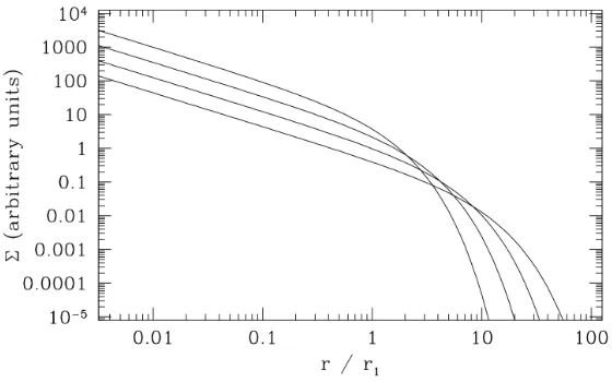
with a diffusion coefficientDand a spatial variablex. Fig. 1 of Pringle (1981) illustrates the viscous evolution of the surface density of a ring of matter in the disk. Initially atτ=0, all matter resides in a narrow ring of massmat radiusr0(radial distance from the star)
Σ(r,t=0)= m 2πr0
δ(r−r0) , (3)
with the Dirac delta functionδ(r−r0). With time, the mass initially contained in a narrow ring, spreads out to both sides of the initial ring. Most of the mass moves inward, while some smaller amount of mass moves out to larger radii to take up the angular momentum.
If we parametrise the viscosity as a power law of radius (this would be the case for the Shakura-Sunyaevαviscosity if both the surface density and the temperature are also a power laws)
ν∝rγ , (4)
we can obtain the self-similar solution of a spreading disk, also derived by Lynden-Bell & Pringle (1974). We assume that the initial surface density profile is that of a steady-state disk with an expo-nential cutoffatr=r1(the scaling radius)
Σ(˜r,t=0)= 3πν(C
r1)˜rγexp(−r˜
(2−γ)) , (5)
where ˜r≡r/r1. Without the details of derivation, the solution has then the form
Σ(˜r,t)= C 3πν(r1)˜rγ
θ−(5/2−γ)/(2−γ)exp
−r˜(2−θγ)
. (6)
Here, the scaled time variableθis related tots, the viscous scaling time, through
θ = t
ts +
1 (7)
ts =
1 3(2−γ)2
r2 1 ν(r1) .
Figure 1. The self-similar solution to the disk evolution equation is plotted for a viscosityν∝r. The initial surface density tracks the profile for a steady-state disk (Σ∝r−1, Eq. (30) from the chapter "Disk formation and
structure" by Dominik (2015) forTc∝r−1/2) at small radii, before cutting offexponentially beyondr=r1. The
curves show the surface density at the initial value of the scaled time variableθ=1 and at subsequent timesθ=2, θ=4, andθ=8 (caption and figure from Phil Armitage, private communication).
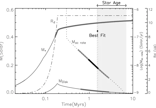
A simulation of the disk formation and viscous spreading phase has been done by Hueso & Guillot (2005). Fig. 2 shows the viscous evolution of a star+ accretion disk system with realistic input parameters. The figure shows thick grey lines superimposed on each plotted quantity. Each one shows the range of time for which that quantity agrees with the available observations. This example shows how an 800 AU disk can be formed by viscous diffusion of an initially much smaller disk, with a centrifugal radiusrc=11 AU. At the end of the simulation, the star has almost acquired its final mass
(here 0.5Mat 10 Myr). The disk mass grows until a few times 105yr. After that the initial cloud has largely dispersed and now the disk material slowly accretes onto the star.
2.2 Gravitational instabilities
For massive disks, self-gravity can become important and introduce another sort of instability. In general, self-gravity will tend to locally clump material together, on a clumping (free-fall) timescale
tff. This process will be counteracted by shear motions and also by local gas pressure. It can be shown that gravity wins this competition if the clumping timescale is short compared to the time scaletPon
which sound waves cross a clump, and to the shearing timescaletshearon which shear can destroy it. For a clump of sizeΔrand massm∼π(Δr)2Σ, the three timescales can be written as
tff ∼
(Δr)3
Gm ∼
Δr
πGΣ (8)
tp = Δ
r cs
(9)
tshear = 1
r
dΩ dr
−1
Figure 2. Evolution of star mass M∗ and disk mass Mdisk as a function of time with masses in solar units
(corresponding axis to the left) for a viscosityα=0.01. The accretion rate onto the central star is shown as a dotted line (corresponding axis: first to the right). The evolution of the centrifugal radiusrc(labeled for some reasonRd in the plot) is shown as a dash-dotted line (corresponding axis: far-right and units are AU not UA). Gray curves and the hashed region indicate time sequences when selected observational constraints are verified (from Hueso & Guillot 2005, reproduced with permission cESO).
Comparing these timescales, the "Toomre Q" parameter (Toomre 1964) indicating whether the disk is stable can then be written as
Q= csΩ
πGΣ . (11)
The disk becomes unstable against self-gravity atQ<1.
2.3 Dead zones
Dead zones are regions of the disk that are inactive in terms of of angular momentum transport. If the viscosity in the disk is caused by the magneto-rotational instability (MRI), they arise as soon as the ionization degree drops below the critical ratio between electron and total gas densityne/ntot∼10−12. Sources of ionization are collisional ionization, thermal ionization (only in the inner disk rim exposed to the stellar radiation), X-ray and cosmic ray ionization. The low level of ionization arising from cosmic rays or X-rays deep inside the disk is sufficient to sustain turbulence through MRI. Cosmic rays can penetrate column densities of 50 g/cm2and thus reach the midplane except for the inner few AU in a very massive disk with a steep surface density profile. X-rays penetrate column densities of∼100 g/cm2. However, stellar X-rays (coming from the corona) will penetrate the disk radially and quickly reach these column densities. Only X-rays coming from high above the disk (e.g. from a stellar jet or from the accretion flow onto the star) can be expected to reach the midplane also at larger radii.
dead zone. This has consequences for the density and pressure profile in the disk, causing e.g. a local inversion in the pressure gradient. Such a pressure gradient inversion can lead to the accumulation of small dust particles, increasing locally the dust:gas mass ratio in the disk. We will get back to this point in the chapters on planetesimal formation.
2.4 FU Orionis outbursts
FU Orionis stars are variable pre-main sequence stars that undergo optical outbursts of several mag-nitudes. The outbursts show fast rises on timescales of 1 yr and slow decays with timescales of the order of 50-100 yr. These systems are thought to undergo episodic mass accretion from the inner disk with accretion rates being as high as 10−4M/yr. How can we explain these episodic high accretion rates within the just developed concept of accretion disks?
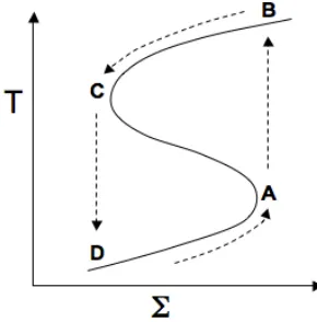
Figure 3.Schematic ’S curve’ for the disk thermal instability (adapted from Hartmann 1998, Fig.7.11).
The basic idea is that the inner disk is extremely opaque and thus cannot efficiently radiate away energy that has been inserted into the gas through the viscous accretion process. The inner disk could then be hotter than 104 K. This also implies that the original assumption of a thin disk (disk height
z r) breaks down and the disk has a very large scale heighth/r∼0.4. Under these circumstances,
the inner 1 AU of the disk can have enough mass to fuel an FU Orionis outburst event. The event itself could be triggered by thermal instabilities that are due to the temperature dependence of the gas opacity. This can be illustrated using a curve that describes the loci of thermal equilibrium in the
solution becomes again the low accretion solution on the lower arm of the ’S curve’ (point D). The timescale of such thermal instabilitiestthis shorter than the viscous timescaletvis
tth∼
h r
2
tvis , (12)
and thus much closer to the typical 1 yr rise seen in the FU Orionis outburst events.
2.5 Gap formation
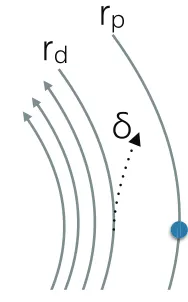
Gaps in disks can be formed in a number of ways. Photoevaporation can open up a gap in the disk and interrupt accretion of material from the outer disk, creating a broad gap that extends all the way to the star. This process will be discussed in the chapter "Ionization and heating by X-rays and cosmic rays" by Güdel (2015). Gaps can also be formed by the interaction of a massive planet embedded in the disk. They result from a competition between torques from the planet on the disk that try to push matter away from the planet, and the viscous forces in the disk that attempt to close the gap (see Fig. 4). We can get an estimate for the gap formation physics by considering an element of gas moving past a planet with massMpthat is embedded in a disk. If, for the time of the flyby, we treat
the gas element as a particle on a hyperbolic orbit past the planet, we can compute the angleδunder which the gas element will be deflected (see Fig. 5). From Kepler’s laws, this angle is
cotδ 2 =
v2 relΔr
2
G2M
p
(13)
wherevrel=rdΩd−rpΩpis the relative velocity caused by Keplerian shear.
For each pass, this deflection corresponds to a change in angular momentum of the gas element of
Δj=−vrelrd(1−cosδ)∼ −
2G2M2
prd
(Δr)2v3 rel
. (14)
Such a pass happens each time the gas element passes the planet, so in intervals ofΔt=2π|Ω−Ωp|,
r
d
r
p
δ
Figure 5.Orbital changes of gas deflected by embedded planets.
and we can integrate this over the different planet-gas-element distances to find the average torque on the gas
˙
J=
∞
Δr0
ΣΔΔj
t2πrd(Δr) . (15)
DevelopingΩaroundΩpand integrating gives
˙
Jgrav=−
8 27
rp Δr0
3 Mp M∗
2
Ω2
pΣr4p . (16)
This is the torque that pushes the disk gas away from the planet. However, the viscous torque also acts on the gas and pushes it back toward the planet. The viscous torques are
˙
Jvisc=M j˙ p=3πΣνr2pΩ (17)
and for gap formation to occur, the gravitational torques need to be larger than the viscous torques, thus
˙
Jgrav≥J˙visc . (18)
If we assume that the Hill radius (the radius of the sphere around the planet where the planet’s gravity dominates over the star’s gravity) is the minimum possible value forΔr, and defining the mass ratio
q=Mp/M, this criterion translates to
q≥qvisc
10ν
Ωpr2
p
(19)
which implies a mass ratio appropriate for Saturn or Jupiter. So planets with masses above the mass of Saturn can open gaps in disks. Smaller planets do not open gaps.
2.6 Disk evaporation
part will be lost due to evapoation processes triggered by stellar and external irradiation by FUV, EUV, and X-ray radiation. This will be covered in more detail in the chapter on X-ray and UV ray effects by Güdel (2015).
3 Particle motion in protoplanetary disks
Terrestrial planets, as well as the cores of giant planets, are made of solids. We therefore need to focus on the dynamics of dust particles in the disk in order to understand how this part of disk matter can be selectively grown to form planets. The two main ingredients in studying the motion of particles in a disk aredrag forcesandgravitational forces.
3.1 Drag forces
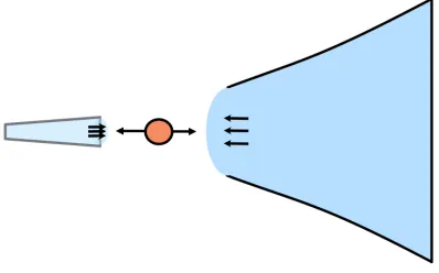
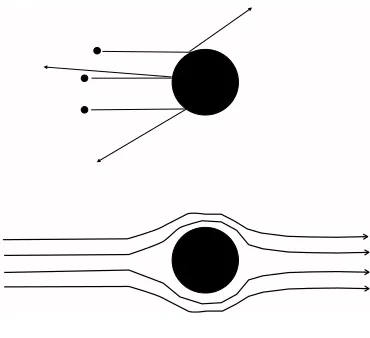
When a particle moves relative to a gas of densityρg, a force will act on the particle, trying to slow it down. There are two different limiting cases for this drag force. When the mean free path for moleculesλf is much larger than the grain radiusa, the drag force can be computed by considering
collisions of individual molecules with a dust particle, without the molecule “knowing” about other molecules for the duration of the collision (Fig. 6, top drawing). If the particle is larger than the mean free path, we have to consider the hydrodynamic flow of the gas around the particle, and the friction is then given by the Stokes law (Fig. 6, bottom drawing).
Figure 6.Gas-grain interaction in the Epstein regime (top) and in the Stokes regime (bottom)
3.1.1 Epstein regime:λfa
Let’s assume the particle moves with a velocityvrel relative to the gas. If this velocity is still much smaller than the sound velocitycs, then the impact velocity of molecules onto the grain is typically
given by the thermal velocityvth=
8kT/(πμmp), whereT is the gas temperature,kis the Boltzmann
constant,μis the mean molecular weight andmpthe proton mass. The velocity of the particle relative
for the friction forceFDtherefore contains the product of these velocities, along with the cross section
of the particle and a geometric factor that depends on the details of the collision (reflection versus diffuse re-emission)
FD=−
4π 3 a
2ρ
gvthvrel (20)
3.1.2 Hydrodynamic (Stokes) regime:λf a
FD=−
CD
2 πa 2ρ
gvrelvrel (21)
The friction coefficientCDdepends on the Reynolds number, and can vary between 0.4 and 24.
CD=
⎧⎪⎪⎪ ⎨ ⎪⎪⎪⎩
24Re−1 Re<1 24Re−0.6 1<Re<800
0.44 Re>800
(22)
with the Reynolds numberRe=2avrel/νmol, i.e.CD=CD(vrel).
3.1.3 The friction time
An important concept for the dynamics of particles is thefriction time tfric, sometimes also called the
stopping time. This is a typical time scale for the coupling of a particle with massmand velocityvto the gas, and it is defined by the equation
tfric=
mv |FD|
(23)
i.e. it is the time to remove the initial momentum of a particle under the assumption that the friction force remains constant. In reality, the force will decrease with the relative velocity, so the friction time is in fact ane-folding time for the relative velocity.
In the Epstein regime and for a spherical particle with radiusa, and densityρmEq. (23) reduces to
an easy to remember expression
tfric= ρm
ρg
a
vth
(24)
Typical values for the friction time for parameters that are typical in the midplane of a minimum mass solar nebula at 1AU from the sun are
tfric,Ep=2 s
ρ
m
2 g/cm3
10−9g/cm3 ρg a 1μm 1 km/s vth (25)
tfric,St=2.7 yr a
1m ρm
2 g/cm3 24
CD
10−9g/cm3 ρg
1 m/s vrel
(26)
3.1.4 The Stokes number
For many processes in the disk it is important to know if the friction time is shorter or longer than other dynamical time scales in the disk. Of particular importance is the comparison with the orbital time in the disk. TheStokes numberis therefore defined as
St= ΩKtfric (27)
3.2 Equations of motion for dust particles
We will now look at the motions of dust particles in a gaseous disk. For this we need to write down the equations of motion for these particles, which we will write in terms of the radial and vertical velocities vr,d, vz,dand specific angular momentum jd=rvφ,d(angular velocity of dustvφ,d, the respective radial,
vertical velocities of gas and its angular momentum are indicated by an indexg). It is straight forward to write down these equations.
Let j=rvφ=r2Ω specific angular momentum (28) gr=−Ω2Kr radial component gravity (29)
gz=−Ω2Kz vertical component gravity (30)
The equations of motion for a dust particle are then dvz,d
dt =gz−
vz,d−vz,g
tfric
(31)
dvr,d
dt =gr+ j2
d
r3 −
vr,d−vr,g
tfric
(32)
djd
dt =− jd−jg
tfric
(33)
3.3 Dust settling
Let us first focus on the vertical motion of a dust particle suspended in a disk. We assume here that the gas has no vertical motion, i.e.vz,g=0. In this case we get from Eq. (31)
dvz,d
dt =−Ω
2
Kz−
vz,d
tfric
(34)
Withvz,d=dz/dtandΓ:=1/tfric
d2z dt2 + Γ
dz
dt + Ω
2
Kz=0 (35)
which is the equation of a damped oscillator. We assume for the moment thatΓ =const (this implies ρ=const, i.e. we are close to the midplane where the density hardly changes). We try a waveAnsatz
as the solution and arrive at a dispersion relation
z(t)=z0eiωt with ω= 1 2
iΓ±
4Ω2
K−Γ2
(36)
For a realω, we will get an oscillation with frequencyω. For a complexωthe solution will be a damped oscillation, and for a purely imaginaryω, a slow settling motion will occur. The criticalΓfor the fastest non-oscillatory motion is
Γcrit=2ΩK ⇒
σ
m =
ΩK
2ρgvth ⇒
acrit= ρgvth 2ρmΩK
(37)
corresponding to a critical particle size
acrit=125 cm
ρ
g 10−9g/cm3
vth 1 km/s
2 g/cm3 ρm
2π/yr ΩK
3.3.1 Equilibrium speed and settling time
For particles with a short friction time, an equilibrium drift velocity is reached quickly. We restrict ourselves here to the Epstein case, because only then the friction times are in fact short. Assuming dvz,d/dt=0 in Eq. (34) gives
vz,eq= ρm
ρ
a
vth Ω2
Kz . (39)
The settling velocity is inversely proportional to the gas density. Since the vertical gas density drops of exponentially withz, this means that the settling speed in the upper layers of the disk will be very fast. We can define a local timescale for settling using the vertical distribution of gas (Eq. 27 in the chapter "Disk formation and structure" by Dominik 2015). We find for the settling time scale
tsettle= 2 π
Σ ρmaΩK
exp ⎛ ⎜⎜⎜⎜⎝− z2
2H2 gas
⎞
⎟⎟⎟⎟⎠ (40)
The strongzdependence implied by this formula indicates that the upper layers should become de-pleted of dust quickly, unless a mixing process counteracts the settling. In reality, disks are thought to be turbulent, and the depletion will not be complete.
3.3.2 Settling and turbulent diffusion
If the disk is not laminar but turbulent, the turbulent gas motions try to counteract the systematic settling of dust particles. Gas elements that move up due to turbulence will take small particles that are coupled to the gas with them and in this way try to weaken the gradient in dust density that is caused by settling. This process is described by a diffusion equation which we give here without further derivation
∂ρd
∂t =D
∂ ∂z ρ∂ ∂z ρ d ρg +∂∂ z Ω2
Ktfricρdz
. (41)
Here the diffusion coefficientDdescribes the diffusion due to turbulent motions. In general, Eq. (41)
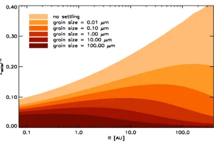
must be solved numerically. Fig. 7 shows the result of such a calculation for a disk around a star (see also Dullemond & Dominik 2004). It shows that small particles remain present at large heights in the disk, while large grains get concentrated close to the midplane. This can also be seen from an analytical solution that exists in the case whereρgis constant (i.e. close to the midplane of the disk, clearly inside the first pressure scale heightHgas). This solution is
ρd
ρg = ρ
d
ρg
z=0 exp
⎛ ⎜⎜⎜⎜⎝− z2
2h2
d
⎞
⎟⎟⎟⎟⎠ (42)
where
hd=
D
Ω2
K
tfric (43)
is the scale height of the concentration of a dust component with friction timetfric. So each grain size will get its own concentration scale height.
If the turbulence diffusing the dust is the same process that also causes angular momentum trans-port, we can write
D=α cs Hgas (44) and find hd Hgas α
ΩKtfric
Figure 7.Heights under which 90% of the grains of a given size are located in the presence of competing settling and vertical mixing.
3.4 Radial drift
We now come to one of the key concepts and also problematic issues of planet formation: radial drift of solid matter. To understand where this problem stems from, we need to look at the tangential momentum equation for the gas. We have encountered this equation earlier (Eq. 13 in the chapter by Dominik 2015) and write it here in a different way, making use of the definitions in Sect. 3.2,
(rΩg)2=(rΩK)2+
r
ρg ∂p
∂r or j
2 g= j2K+
r3 ρg
∂p
∂r . (46)
wherepis the gas pressure.
This equation shows that for the gas, the centrifugal accelerationrΩgand the gravitational accel-erationrΩKare not equal if the gas has a non-zero pressure gradient. Normally one would assume
that the gas pressure decreases outward, so that the pressure gradient is a negative number. In this case, the angular velocity of the gasΩg will besmallerthan the Kepler angular velocityΩK.
How-ever, if, for some reason, the pressure gradient is positive, the gas can also movefasterthan Keplerian. The deviation from Keplerian motion is the root cause for radial drift of solid particles, because these particles have only few collisions and therefore experience no pressure. So for solid particles, Kep-lerian orbit is always “desirable”. However, the details depend on how well particles couple to the gas.
3.4.1 Radial drift, well-coupled grains
We recall the equations for the dust motion
dvr,d
dt =gr+ j2
d
r3 −
vr,d−vr,g
tfric
(47)
djd
dt =− jd−jg
tfric
A well-coupled particle with Stokes number much smaller than 1
tfricΩk 1 (49)
will move with the gas, so that we have jd=jg. Using Eq. (47) and the assumption that the gas does not move vertically (vr,g=0), we find
dvr,d
dt =gr+ j2
g
r3 − vr,d
tfric
. (50)
Inserting Eq. (46) and assuming equilibrium (dvd,r/dt=0) we find
vr,d =tfric 1 ρg
∂p
∂r (51)
So well-coupled particles will drift in the direction of rising pressure, because, moving with the gas, they either feel to much or too little centrifugal force for a stable Keplerian orbit.
3.4.2 Radial drift; poorly coupled particles
Poorly coupled particles have Stokes numbers much larger than 1, i.e.
tfricΩk1 (52)
These particles largely ignore the gas and just move with the Keplerian velocity, so we can assume
jd=jK. Any radial motion must then come from tangential forces, so we return to Eq. (48) but write
jKinstead of jd, apply the product rule for differentiation, and make use of dr/dt=vr,d
d jd
dt
d jK
dt =vr,dvK+r dvK
dt =
dr dtvK−r
1
2rvKvr,d =
1
2vr,dvK . (53)
We express jg using Eq. (46) and approximate using a Taylor expansion and the assumption that the pressure gradient is only a small correction to the centrifugal force
jg=
j2
K+
r3 ρg
∂p
∂r jK+
1 2jK
r3 ρg
∂p
∂r . (54)
Inserting this into Eq. (53) and solving for the radial velocity we find
vr,d=
1 Ω2
Ktfric
1 ρg
∂p
∂r (55)
Figure 8.The total inward radial velocity ofα=10−3(Figure from Brauer et al. 2008, reproduced with
permis-sion cESO).
3.4.3 Radial drift: Summary
To summarise the results about radial drift we can say the following. The pressure gradient in the disk is felt by the gas, but not by the dust. This leads to radial motion of dust particles. The physical reasons are slightly different in the well-coupled and poorly-coupled cases, but the overall effect is that particles drift in the direction of rising pressure. The drift velocity is low for both very low and very large Stokes numbers. However, around St=1, the velocity can be about 1% of the orbital speed, so that particles move toward the star within 100 orbital timescalesunless they can grow significantly in the same time interval.Figure 8 shows the results from a calculation of drift speeds in the literature (Brauer et al. 2008). Since particles move toward larger pressure, particles can be trapped in pressure maxima if these exist in the disk. Pressure maxima can be created outside a gap opened by a planet, or in the center of a vortex in a disk. Typically, St=1 particles are trapped very efficiently in such maxima, while smaller particles can easily be removed from a trap by turbulent mixing.
3.5 Dust layer instabilities
We have seen above that dust grains will settle toward the midplane. If this dust layer becomes very thin, it could in principle become gravitationally unstable (just the dust, not dust and gas!). We only mention the basic facts here, for more details see for example the discussion in Armitage (2010).
The Toomre number for an ultra-thin disk is
Q=
h r
M
πr2Σ
d
(56)
and the requirement thatQ<2 for a gravitational collapse leads to a critical densityρcand instability
wavelengthλcof
ρc=
3M
2πr3 (57)
λc=
4πGΣd
Ω2
K
This seems like an ideal way to produce complete planetesimals in just one step, directly from pebbles, and was introduced as such in a famous paper by Goldreich & Ward (1973). However, this paper ignored the importance of self-excited turbulence that is inevitable stirred up once the settling becomes too efficient. Once the dust has settled enough to produce a local dust-to-gas ratio of about unity, the dust will start to move at Keplerian speeds and drag the surrounding gas with it. This creates a vertical shear region which is Kelvin-Helmholtz unstable and produces turbulence, making any further settling impossible. It turns out that the dust densities that can be reached in this way are not large enough to trigger the instability.
4 From dust to planetesimals
Growing from the small dust grains found in the interstellar medium, in molecular clouds and also in protoplanetary disks is a formidable undertaking. It is a growth in particle radius from 1μm to 10000 km, or in other words 14 orders of magnitude in size or 42 orders of magnitude in mass.
4.1 Collisions
In order to have particles collide, they need to have relative velocities. We have already seen that there are a number of processes that cause relative motions between particles, such as vertical or radial drift whose speed depends on particle size. The most basic source of relative velocities is Brownian motion which gives particles kinetic energy just like gas particles as a given temperature have thermal velocities. Of course, the velocities of particles will be much smaller than those of molecules, because their masses are much larger. The typical relative velocityΔvB between two particles of massesm1 andm2due to thermal motions (Brownian motion) is
ΔvB=
8kT(m1+m2) πm1m2
. (59)
At a temperature of 300 K, velocities for 0.1μm particles are of the order of cm/s.
In order to see if collisions will play a role, we can make a simple estimate of the collision fre-quency. The typical time scale for a particle to collide with another particle is
tcollide= 1
nσΔv (60)
wherenis the number density of particles, σis the collision cross section, and Δvis the relative velocity. For simple estimates we will assume that there is only one kind of particle with massm
providing the entire dust densityρd = fdgρg with fdg indicating the dust to gas mass ratio. The number density of particles is thenn=fdgρg/m. If the particles are spherical and gravity does not play a role, the collision cross section isσ=4πa2whereais the grain radius. Filling in all these quantities we find for the collision time
tcollide =
m
4πfdgρga2Δv (61)
and for the special case of Brownian motion
tcollide,B= πρ3/2
m a5/2
6√3kT fdgρg
24
a
1μm 5/2
Compared with the evolutionary timescale of disks, this is a very short time, so collisions will be important for the smallest particles. As particles get bigger, other sources of relative velocity kick in and lead to collision times of
tcollide=
aρm
3fdgρΔv 316
a
1 cm
ρm
3 g cm−3 0.01
fdg
10−10g cm−3 ρg
1 m/s Δv
yr (63)
The timescale is the same for 1 cm particles at velocities of 1 m/s, and for 1 m particles at velocities of 100 m/s. While this time scale is still much smaller than the disk life time, it is larger than radial drift time scales for particles with St1 (∼100 years at 1 AU). Therefore, we can already see that something needs to be done about growth time scales. One interesting aspect is increasing the dust to gas ratio fdg to 0.1 or even 1 would help greatly. However, another problem is that large particles can reach large relative velocities. Will particles really stick at such velocities, or rather destroy each other?
4.2 The coagulation equation
To follow the evolution of the particle sizes, one needs to solve a complex integro-differential euqation, the so-called Smoluchowski or coagulation equation. This equation considers the number of particles in a certain mass range, n(m) dm. The equation describes the change in time of this quantity by processes that add particles to and remove particles from in this size range. Particles are added if other particles collide and grow to end up in this size range. Particles are removed when they themselves collide and grow out of the size range. The simplest form of this equation is
dn(m) dt =
1 2
m
0
A(m,m−m)n(m)n(m−m) dm−n(m) ∞
0
A(m,m)n(m) dm (64)
The quantitiesA(m1,m2) are called the reaction kernels, they describe how frequently a specific process happens for a pair of particles with massesm1andm2. In our case the kernel can be written as
A(m1,m2)=P(m1,m2,Δv)Δvσ(m1,m2) (65)
whereP indicates the probability that particles 1 and 2 will stick upon collision with the relative velocityΔv, andΔvσdenotes the collision rate per particle with massm1and per particle with mass
m2.
Please note that Eq. (64) is really only a simplified version of the real equation that needs to be solved. First of all, we need to solve the equation at many different locations in the disk, simultane-ously. Also, because particles move in the disk, an advection term covering particles arriving at and leaving certain locations must be included. Furthermore, particles may have other properties besides mass, for example porosity, charge, collision history, which may affect the probability of collisions and, therefore, the kernel in the integral. Collisions at high velocities will most likely lead to de-struction rather than growth, and these terms are not yet included at all. Finally, particles may have other properties besides mass (such as porosity or charge) that may influence their behavior. A full description of the results of such calculations is beyond the scope of this chapter.
4.3 Limits to dust growth
1. Drift barrier:The drift speed of particles increases as they grow, and until they reach a Stokes number of about unity. Detailed computations often show that at some point the drift timescales are shorter than the growth timescales, limiting the maximum size of particles present at a specific location.
2. Fragmentation barrier: Relative (collision) velocities also increase with particle size. This is caused by the increasing influence of turbulence, but also of radial drift. If collisions become destructive, this limits the size particles can reach - even though a small number of lucky parti-cles can still get through, and it provides a way to replenish the disk with small dust grains that in a growth-only environment would disappear quickly.
3. Bouncing barrier: Laboratory experiments show that, before collisions become destructive, there is a regime of velocities where particles bounce. While the bouncing barrier can be over-come when the velocity distribution or the size distribution is wide enough, this can still be a mechanism that stalls or slows growth at a certain size.
All these mechanisms form serious challenges to the growth of large objects by simple aggrega-tion. A number of modifications to the process are currently discussed to enable growth.
1. Extremely porous particles. If particle growth leads to extremely porous grains that are never really compacted, it is possible that growth will outrun radial drift and produce planetesimal-sized objects directly, The objects could then be compacted at a later stage by self-gravity and by gas pressure forces (Kataoka et al. 2013). In particular in the outer regions of disks where the sticking and mechanical properties of icy aggregates are governed by the material properties of ices, this mechanism is seriously considered.
2. Direct planetesimal formation by streaming instability. While a gravitational instability of a set-tled dust disk by itself is ruled out, the so-called streaming instability that acts on particles with Stokes numbers not far from unity can lead to the concentration of particles. If that concentra-tion mechanism becomes really effective, super-critical densities for gravitational collapse can be reached, forming bodies as large as the asteroid Ceres in one step (Johansen et al. 2007).
3. Turbulent and vortex concentration. A number of hydrodynamic phenomena can lead to con-ditions under which particles will be concentrated in local (purely radial, or even radial and azimuthal) pressure maxima. Dust concentrated in such regions has improved growth con-ditions like slower or non-existing drift motions, and higher densities, that might enable the formation of planetesimals after all.
A full discussion of all these processes is well beyond the scope of this lecture. But certainly the growth of dust grains to sizes so large that we cannot see them anymore with current observational techniques does have major impact on interpretation of observations. In fact, when the remaining chapters in this lecture series talk about the dust mass in the disk, they usually only refer to the
detectable dust mass, i.e. mass contained in particles with sizes up to centimeters or so.
Eventually, however, when the bodies growing in the disk reach the masses of giant planets that can affect the disk structure (by creating gaps or triggering spiral waves), then they start to affect the observations of disks again. With the new imaging capabilities at a number of telescopes, analyzing these structures will move into the focus of the study of protoplanetary disks.
References
Armitage, P. J. 2010, Astrophysics of Planet Formation (Cambridge University Press)
Brauer, F., Dullemond, C. P., & Henning, T. 2008, A&A, 480, 859
Dominik, C. 2015, in EPJ Web of Conferences, Vol. 102, Summer School on Protoplanetary Disks: Theory and Modeling Meet Observations, ed. I. Kamp, P. Woitke, & J. D. Ilee
Dullemond, C. P. & Dominik, C. 2004, A&A, 421, 1075
Goldreich, P. & Ward, W. R. 1973, ApJ, 183, 1051
Güdel, M. 2015, in EPJ Web of Conferences, Vol. 102, Summer School on Protoplanetary Disks: Theory and Modeling Meet Observations, ed. I. Kamp, P. Woitke, & J. D. Ilee
Hartmann, L. 1998, Accretion Processes in Star Formation (Cambridge University Press)
Hueso, R. & Guillot, T. 2005, A&A, 442, 703
Johansen, A., Oishi, J. S., Mac Low, M.-M., et al. 2007, Nature, 448, 1022
Kataoka, A., Tanaka, H., Okuzumi, S., & Wada, K. 2013, A&A, 557, L4
Lynden-Bell, D. & Pringle, J. E. 1974, MNRAS, 168, 603