Wireless Automated Drone Tank Control
Pokharkar Mayur S.
Institute of Knowledge College of Engineering
Pimple Jagtap, pune
[email protected]
Borkar Rupali R.
Institute of Knowledge College of Engineering
Pimple Jagtap, pune
[email protected]
Thite Archana S.
Institute of Knowledge College of Engineering
Pimple Jagtap, pune
Jogdand Varsha L.
Institute of Knowledge College of Engineering
Pimple Jagtap, pune
[email protected]
Abstract—
Defense is one of the major aspect
considered today, as history defines it, there has
been many war occurrence’s that has that has
made world speechless and baffled. Till now
military –defense, attack has been one of the major
platform to show strength to existing world.
In battlefield many soldier’s fight for the glory
of their nation, they risk their life in danger; many
of them die in battlefield. We cannot stop war but
we can reduce the amount of death occurrences of
our soldier’s. Considering this in mind we have
developed a drone tank which is basically an
unmanned ground vehicle. Our drone tank is
designed and developed for some application
specific missions to operate predominantly in
hazardous environments. In our work, we have
proposed the usage of our tank in border area, for
surveillance. It is manually control with camera
mounted on to identify the opponent and a gun to
attack. In this paper is proposed an
accelerometer-based system to control an industrial robot using
two
low-cost
and
small
3-axis
wireless
accelerometers.
Keywords—
unmanned ground vehicle; drone tank;
accelerometer; surveillance
I. INTRODUCTION
An unmanned ground vehicle (UGV) is a vehicle that operates while in contact with the ground and without an onboard human presence. UGVs can be used for many applications where it may be inconvenient, dangerous, or impossible to have a human operator present. Generally, the vehicle will have a set of sensors to observe the environment, and will either autonomously make decisions about its
behavior or pass the information to a human operator at a different location who will control the vehicle through teleportation.
In their 1930s, the USSR developed Teletanks, a machine gun-armed tank remotely controlled by radio from another tank. These were used in the Winter War (1939-1940) against Finland and at the start of the Eastern Front after Germany invaded the USSR in 1941. During World War II, the British developed a radio control version of their Matilda II infantry tank in 1941. Known as "Black Prince", it would have been used for drawing the fire of concealed anti-tank guns, or for demolition missions. Due to the costs of converting the transmission system of the tank to Wilson type gearboxes, an order for 60 tanks was cancelled.
There are two classes of unmanned ground vehicles: Remote-Operated and Autonomous.
Remote-Operated:
A remote-operated UGV is a vehicle that is controlled by a human operator via interface. All actions are determined by the operator based upon either direct visual observation or remote use of sensors such as digital video cameras. A basic example of the principles of remote-operation would be a remote controlled toy car.
UGVs are also being developed for peacekeeping operations, ground surveillance, gatekeeper/checkpoint operations, urban street presence, and to enhance police and military raids in urban settings. UGVs can "draw first fire" from insurgents - reducing military and police casualties. Furthermore, UGVs are now being used in rescue and recovery missions. These robots were paramount following 9/11, when searching for survivors at Ground Zero.
II.LITERATURE SURVEY
In [2]‟ have presented an unmanned ground vehicle with the facility of measurement of humidity, temperature and illumination, video and audio clips to get the information of the environment through which UGV navigates. They have discusses the real time embedded implementation of this obstacle mapping system on a small Unmanned Ground Vehicle (UGV) to support real time obstacle avoidance, object identification by image processing and proposes self- protection against high temperature. These activities are a part of a larger effort to establish a theoretical foundation for autonomous and cooperative guidance and solutions in adversarial environments.
In [3]‟have proposed system that uses a three axis accelerometer used to read different types of movements. But carrying extra circuitry on the hand involves attaching a number of accelerometers with the hand, this causes irritation to the user, there may be loose connection in the system which may result in abnormal outcomes.
In [4]‟ have used a frequency response method of system identification for an Unmanned Ground Vehicle. Before system identification could begin, analysis and design of certain hardware components were performed. The accelerometer feedback had to be modified for accurate GPS data. Sensor calibration and installation to the vehicle‟s subsystems was necessary as well prior to response analysis. The design of the experiments and analysis of data collected, primarily for the steering subsystem, are discussed, and their involvement in modeling the system in a mathematical form is explained in detail. Also included is the application of controllers to reduce error from input commands for future functionality as an autonomous vehicle
In [5]‟ the authors have presented a dynamic visual attention method used to segment the scene into moving objects— vehicles and pedestrians—and background, without using a reference image or modeling the background. Its disadvantages is that parameter this parameter tuning does not depend on each different situation stored in a video sequence taken from the camera, but only on the predefined attention focuses and also this method model used to monitor static environments.
In [6]‟ presented a paper human-machine interaction is becoming widespread. So, with the introduction of new technologies the gap between machines and humans is being reduced to ease the standard of living. Gestures have played a crucial role in diminishing this gap. This paper deals with design and implementation of an accelerometer- based hand gesture controlled robot controlled wirelessly using a small low cost, 3-axis accelerometer. The current emerging technology in the field of science is Robotics. It is the new emerging booming field of great use to people in the coming years. These days a number of wireless robots are being developed and put to various applications and uses. In order to enhance the contribution of robot in our daily lives we
need to find an effective way of communicating with robots hand Gesture Control Robot is a kind of robot which is controlled by the hand gestures and not by using buttons. RF receiver module is then decoded using a decoder IC which is then processed by a microcontroller and passed onto a motor driver to rotate the motors in a special configuration to move the robot in the same direction as that of the hand.
In [7]‟ have built a prototype self- controlled robot (called as UGV) to undertake missions like border patrol, surveillance and in active combat both as a standalone unit (automatic) as well as in co-ordination with human soldiers (manual). Likewise, command controlled mode, we use another specific mode called, self-control mode or automatic mode. In this mode, UGV is maneuvered automatically and it capable of travelling from one point to another point without human navigation commands. It uses GPS, magnetic compass and adjusts strategies based on surroundings using path planning and obstacle detection algorithm.
III.SYSTEMOVERVIEW
A. System Description
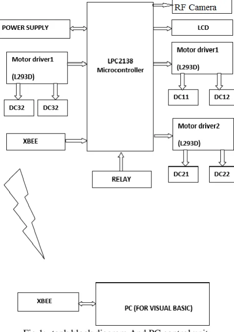
Fig 1:- tank block diagram And PC control unit
In this project we have built an unmanned ground vehicle which will be used for military operation such as surveillance, attacking and for spying. In this system we have manually controlling the tank. We have used zigbee technology communication, microcontroller, accelerometer, which will drive the robot, with the commands given by the control unit.
Fig 2:- Control unit (accelerometer)
We have used pc or laptop to give command, the command is given through a visual basic software, the given command is sent via zigbee communication which is interfaced with our laptop or pc through MAX232IC and through serial USB
connector. This command is then given to the microcontroller which is located on our tank.
The microcontroller we are using is an ARM (LPC2134FBD64) this microcontroller is on board with our tank. As the microcontroller receives the given signal, it senses the given command and reacts accordingly. Microcontroller output is then given to motor driver IC which in turn gives signal to connected motors to as to move in desired direction. The motor driver IC we have used is LM293D, The communication in this takes places through zigbee i.e. signal through pc or laptop is send through zigbee communication.
We have buggy mode in our system to drive our tank. In this, we have used two different circuitries to drive our tank. One is on board with our tank which is described as above, another one is used by user itself.
Another circuitry we have used in this we have used an accelerometer to drive our tank with same ARM (LPC2134FBD64) microcontroller. The communication with this two circuitry takes place through zigbee, a key is been used to switch between this two modes. Accelerometer sends a change in voltage signal to microcontroller, which then gives signal to motor driver IC, which in turn provides signal to motor and the tank moves in desired direction. The accelerometer senses the signal in x, y & z axis.
We have used a camera mounted on top of our tank; the camera is mounted in such a way that it can rotate around 360° horizontally and 90° vertically.
The camera provide front view of our robot i.e. this camera forms eyes of our tank through which we can see whatever our tank see‟s, this camera module is connected to TV set turner through we can see live video through our operation. This camera is mounted on gun, laser gun is used to attack on enemy; we have provided provision , along with camera that the gun can rotate around 360° horizontally and 90° vertically.
As a watcher we don‟t know which mode our tank is working on so to indicate which mode is being used we have connected LCD to both of our circuitries.
As a military usage we are in fear that some other user may drive this vehicle, it may be used for wrong purpose ,so to avoid this we have used an encrypted algorithm to give command to robot an it is decrypted by the on board circuitry in our tank. So, no other user can have access to control our tank.
B. HARDWARE REQUIREMENTS a. Accelerometer Sensor
vibration. Tilting an accelerometer along its measured axis, gives the gravitational force relative to the amount of tilt.
Fig 3:-Accelerometer sensor
As shown in Fig.3, there are three axes that can be measured by accelerometer and labeled as X, Y and Z with each axis representing separate degree of freedom (DOF) and the data at that corresponding axis is turned into analog form. They are used in Mobile devices, Gaming systems, Disk drive protection, Image stabilization, Sports and health devices applications.
b. Microcontroller
This generation introduced the Thumb 16-bit instruction set providing improved code density compared to previous designs. The most widely used ARM7 designs implement the ARMv4T architecture, but some implement ARMv3 or ARMv5TEJ. All these designs use Von Neumann architecture, thus the few versions comprising a cache do not separate data and instruction caches.
Some ARM7 cores are obsolete. One historically significant model, the ARM7DI is notable for having introduced JTAG based on-chip debugging; the preceding ARM6 cores did not support it. The "D" represented a JTAG TAP for debugging; the "I" denoted an ICE-Breaker debug module supporting hardware breakpoints and watch points, and letting the system be stalled for debugging. Subsequent cores included and enhanced this support.
It is a versatile processor designed for mobile devices and other low power electronics. This processor architecture is capable of up to 130 MIPS on a typical 0.13 µm process. The ARM7TDMI processor core implements ARM architecture v4T. The processor supports both 32-bit and 16-bit instructions via the ARM and Thumb instruction sets.
The ARM7TDMI (ARM7-16 bit Thumb tag Debug fast Multiplier enhanced ICE) processor is a 32-bit RISC CPU designed by ARM, and licensed for manufacture by an array of semiconductor companies. In 2009 it remains one of the most widely used ARM cores, and is found in numerous deeply embedded system designs. The ARM7TDMI-S variant is the synthesizable core.
Microcontroller ARM-7 LPC2138 has flash memory. The programming of this microcontroller is very easy. It is used to interface with gate motor driver.
c. Motor Driver
The Device is a monolithic integrated high voltage, high current four channel driver designed to accept standard DTL or TTL logic levels and drive inductive loads (such as relays solenoids, DC and stepping motors) and switching power transistors. To simplify use as two bridges each pair of channels is equipped with an enable input. A separate supply input is provided for the logic, allowing operation at a lower voltage and internal clamp diodes are included.
This device is suitable for use in switching applications at frequencies up to 5 kHz. The L293D is assembled in a 16 lead plastic package which has 4 center pins connected together and used for heat sinking The L293DD is assembled in a 20 lead surface mount which has 8 center pins connected together and used for heat sinking.
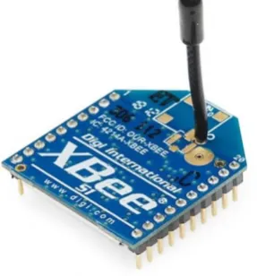
d. Zigbee
ZigBee is a low-cost, low-power; wireless mesh network standard targeted at wide development of long battery life devices in wireless control and monitoring applications. Zigbee devices have low latency, which further reduces average current. ZigBee chips are typically integrated with radios and with microcontrollers that have between 60-256 KB flash memory. ZigBee operates in the industrial, scientific and medical (ISM) radio bands: 2.4 GHz in most jurisdictions worldwide; 784 MHz in China, 868 MHz in Europe and 915 MHz in the USA and Australia. Data rates vary from 20 Kbit/s (868 MHz band) to 250 Kbit/s (2.4 GHz band).
e. Liquid Crystal Display
LCD is used in a project to visualize the output of the application. We have used 16x2 LCD which indicates 16 columns and 2 rows. So, we can write 16 characters in each line. So, total 32 characters we can display on 16x2 LCD.LCD can also be used in a project to check the output of different modules interfaced with the microcontroller. Thus LCD plays a vital role in a project to see the output and to debug the system module wise in case of system failure in order to rectify the problem
C. FLOWCHART
a. Control Unit
Fig 5:- control unit b. Reception Unit
Fig 6:- Reception Unit
IV.RESULTANDDISSCUSION
A. Result
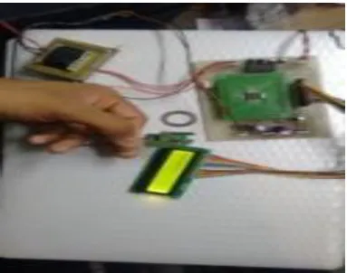
Hardware transmitting view.
.
Reception circuitry mounted on drone tank.
Top view of Drone Tank
Side view of Drone Tank
b.
DiscussionThis model is prototype and if developed as per the standards it will be a good weapon. The main feature of remotely aiming is very useful.
Again this can be used for patrolling on borders, spying, surveillance, on borders. In short it is „Armed Machine Soldier‟.
It has additional provision that it can be used in civilian area. By installing long range communication technique efficiency can be increased.
V.CONCLUSION
With this project we actually prevent soldier‟s life. With the help of our drone tank we reduce amount of risk incorporated on our soldiers.We have consumed less cost to build it. With this project we have maintain documentation about the Drone Tank. So that we actually provide help in various military operations as well no military operations.
So, it is helpful in military purposes to save, prevent and attack and to secure human lives which are in danger.
VI. FUTURE SCOPE
By implementing two or more tanks we can form a swarm intelligence network.
We can add image processing as well as GPS co-ordination in our tank.
We can also implement digital signal processing in our tank.
Acknowledgment
It gives us immense pleasure in presenting the report on “Wireless Automated Drone Tank Control”. The joy and satisfaction that come along with successful completion of any work would be incomplete unless we mention the people who made it possible .There are many people, we like to thank for their contribution in completing this report successfully.
First we would like to mention a special thanks to our respected Project Guide Varsha Jogdand who has really taken lot of efforts to get this project at individual level and also given us a continuous and immense support, suggestions and courage to complete this task. She has applied a constant guiding force to help us prepare and complete the project on schedule .We feel extremely fortunate to have worked under our project guide Varsha Jogdand.
We would also like to thanks our H.O.D Prof.Y.V.Lathkarsir for his faith in us and processing our report. We would also like to thank to entire Electronics & Telecommunication Department Faculty for giving invaluable guidance.