An Efficient Iris Recognition System using
Dual-tree Complex Wavelet Transform
Neelam T. Rakate#, Prof. U. A. Patil* #
PG Student, Department of Electronics Engineering, Shivaji University DKTE Ichalkaranji, Maharashtra, India
*
Assistant Professor, Department of E & TC Engineering DKTE Ichalkaranji, Maharashtra India
Abstract— The main idea behind this paper is to recognize a
person by comparing his/her iris features with an iris feature database. A key and still open issue in iris recognition is how best to represent such textural details using a compact set of features (iris features). To solve this, here we have proposed a novel approach of feature extraction of iris image using Complex Dual-Tree Discrete Wavelet Transform(C-DT-DWT) to obtain the features in 12 different directions as against 3 and 6 directions in Conventional Discrete Wavelet Transform (DWT) and Real Dual-Tree Discrete Wavelet Transform (R-DT-DWT) respectively. For the dual filter tree, we have selected two linear phase biorthogonal filter sets of same lengths (based on Selesnick’s approach) which are used to filter each signal for quantization to 207-300 byte iris feature codes. Then the Hamming distance is used to match two iris codes. The optimum Hamming distance threshold is 0.20. The numbers of filter bank stages used are 4. The experimental results on UPOL database shows good reliability and performance, so it is promising to be used in a personal identification system.
Keywords— Biometrics, Complex Wavelet Transform, Feature extraction, Hamming distance.
I. INTRODUCTION
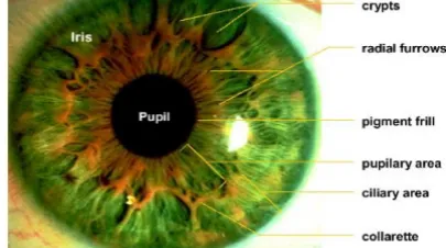
Biometric refers to the automatic identity authentication of a person on the basis of one’s unique physiological & behavioural characteristics. Some of the popular biometrics used includes fingerprints, face, iris, hand geometry, retina, signature, voice, gait, palm print, etc. Among other biometric technologies iris based authentication systems bear more advantages than other biometric technologies do. Iris is externally visible delicate circular diaphragm, which lies between cornea & lens of the human eye; hence it is highly protected internal organ of the eye. It has extremely data rich physical structure as shown in fig. 1.
Fig. 1 The structure of the iris seen in a frontal section
Iris has meshwork of connective tissue that displays arching ligaments, crypts, radial & contraction furrows, pupillary frill, collaratte and freckles. So these
characteristics make each iris to be unique & different from each other. Iris patterns are believed to be unique due to the complexity of environmental & genetic processes that influence the generation of iris patterns. These factors results in textural patterns those are unique to each eye of an individual & even distinct between twins. The iris is considered to be one of the most stable biometric as it is believed to not alter significantly during person’s lifetime. Some of the medical & surgical procedures can affect the overall shape & colour of an iris but the texture remains stable over many decades. Even blind people can use this scan technology since iris recognition technology is iris pattern dependent not sight dependent. Also, the computational time required to perform the identification is relatively low, this makes real time iris detection applications possible.
The iris is, due to its unique biological properties, exceptionally suited for identification. Iris patterns are highly stable and unique as the probability for the existence of two irises that are same has been estimated to be very low, i.e. one in 1072[1]. Hence iris based identification systems are used in high security applications such as credit card authentication, wireless & cell phone based authentication, computer login where iris is used as live password, national border controls where iris is used as living passport.
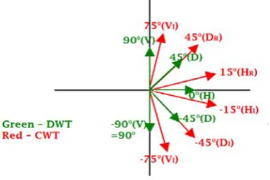
One of the important characteristics of the iris is that it has randomly distributed irregular texture details in all directions. But the problem with iris identification systems is that, how best to represent such a textural details/information using compact set of iris features which will give best matching result. To solve this problem, we have used novel approach of feature extraction of iris images using 2-D dual- tree complex wavelet transform to obtain the features in 12 different directions {-150, -300, -450, -600, -750, 00, 150, 300, 450, 600, 750, 900} as against 3 & 6 directions in conventional discrete wavelet transform & Real dual-tree discrete wavelet transform. Iris features are obtained by computing energies & standard deviation of detailed coefficients in 12 directions. Finally the person is identified by comparing his/ her features with an iris feature database.
II. REVIEW OF WAVELET TRANSFORM
In this section, a brief history, evolution and fundamentals of wavelet transforms are presented. In 19th century, the French mathematician J. Fourier showed that any periodic function can be expressed as an infinite sum of periodic complex exponential functions [5]. This sum is also referred to as a Fourier expansion.
(1)
(2)
Equation (1) represents Fourier transform expansion & equation (2) represents inverse Fourier transform expansion. In equation (1), the signal is multiplied with an exponential term at certain frequency & then we integrate this product. If the result of this integration is a large value, then we can say that the signal has a dominant spectral component at frequency .This means that, a major portion of this signal is composed of frequency
.
If the integration result is zero, then the signal does not contain the frequency at all. Hence, FT is basically used to transform time-domain signal to frequency- time-domain for efficient extraction of information & it is reversible also. But, one of the disadvantages of FT is that it gives only which frequency components exist in the signal. It cannot offer both time & frequency localization of a signal at a time [10]. This means that although we might be able to determine all the frequencies present in the signal, we do not know when they are present. Hence, FT is not suitable if the signal has time varying frequency i.e. if the signal is non-stationary. (e. g. ECG signals).To overcome the limitations of the standard FT, Gabor [5] introduced the initial concept of Short Term Fourier Transform (STFT). In STFT, the signal is divided into small enough segments, where these segments (portions) of the signal can be assumed to be stationary [6]. STFT uses a fixed-length window for analysis. The width of this window must be equal to segment of the signal where its stationarity is valid. Thus, it covers only a portion of signal. Hence disadvantage of STFT is that it gives fixed resolution at all times. For narrow window, time resolution is good but frequency resolution is poorer. For wider window, frequency resolution is good but time resolution is poorer. The need of simultaneous representation and localisation of both time and frequency for non-stationary signals (e.g. music, speech, images) led toward the evolution of wavelet transform from the popular Fourier transform. A wavelet is a small wave which has its energy concentrated in time. It has oscillating wavelike characteristics but also has the ability to allow simultaneous time & frequency analysis and it is suitable for transient, nonstationary or time varying phenomenon. The mother wavelet should satisfy admissibility, regularity property. It should have good smoothness and vanishing moments. The continuous wavelet transform (CoWT) is developed as an alternative approach to the short term fourier transform in order to overcome the resolution
problem. The wavelet analysis is done in a similar way to the STFT analysis, in the sense that the signal is multiplied with a function, similar to the window function in the STFT, and the transform is computed separately for different segments of the time-domain signal. The Wavelet Transform (WT) in its continuous (CoWT) form provides a flexible time-frequency window, which narrows when observing high frequency phenomena and widens when analysing low frequency behaviour [7]. Thus time resolution becomes arbitrarily good at high frequencies, while the frequency resolution becomes arbitrarily good at low frequencies. This kind of analysis is suitable for signals composed of high frequency components with short duration and low frequency components with long duration, which is often the case in practical situations.
The continuous wavelet transform of a function is then defined as-
(3) Where, a- scaling factor, b- shifting factor & is the basis function/ transforming function or it is also known as mother wavelet. * denotes complex conjugate. The scaling factor corresponds to frequency information & shifting factor corresponds to time information of a signal in transform domain. The mother wavelet is a prototype for generating the other window functions. The CoWT has the drawbacks of redundancy and impracticability with digital computers. To overcome drawbacks of CoWT, Discrete Wavelet Transform (DWT) has been introduced.
valued filter bank structure such that the resulting wavelets (real and imaginary parts) after high pass filtering form the (approximately) Hilbert transform pairs at each successive level in the framework of standard DWT decomposition structure. The formulations of analytic filter and associated 2-D dual-tree complex wavelet transform algorithm are discussed in section III.
III.SYSTEM IMPLEMENTATION
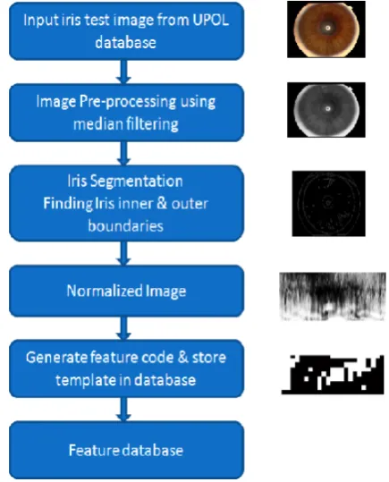
To solve the problem defined above, here we have implemented a novel approach of feature extraction of iris image using 2-D Dual-Tree Complex Wavelet Transform (DTCWT). The main objective is to implement an open-source iris recognition system in order to verify the claimed performance of the technology and emphasis is only on the software for performing recognition, and not hardware for capturing an eye image. Its purpose is high confidence recognition of a person's identity by mathematical analysis of the random patterns that are visible within the iris of an eye from some distance. The system is composed of many numbers of sub-systems, which correspond to each stage of iris recognition. Block diagram of iris recognition system, is as shown in fig. 2.
Fig. 2 Block diagram of Iris Recognition System
These stages are preprocessing – use of digital filters in order to reduce noise, locating the iris region in an eye image & creating a dimensionally consistent representation of the iris region, and feature encoding – creating a template containing only the most discriminating features of the iris using 2-D Dual-tree complex wavelet transform technique. The input to the system is an eye image, and the output is an iris template, which will provide a mathematical representation of the iris region. Such iris templates are stored in database. Finally, hamming distance is used to match two iris templates. Based upon matching result, the decision is made with high confidence whether two codes are from the same iris or from two different irises.
A. Iris Pre-processing
Image pre-processing is used to condition or enhance the input image in order to make it suitable for further processing. Firstly, we transformed the images from RGB to gray level and from eight-bit to double precision thus facilitating the manipulation of the images in subsequent steps. Pre-processing methods use a small neighbourhood of pixels in an input image to get a new brightness value in the output image [3]. In implemented work, Median filter is used to remove salt & pepper noise from an image with less blurring of edges. Before performing iris pattern matching,
the boundaries of the iris should be located because the part of eye carrying information is only the iris part. In other words, it is required to detect the part of the image that extends from inside the limbus (the border between the sclera and the iris) to the outside of the pupil. The Canny edge detection algorithm is optimal edge detector used to find edges of iris inner & outer boundaries. Once the iris region is successfully segmented from an eye image, the next stage is to transform the iris region so that it has fixed dimensions in order to allow comparisons. The dimensional inconsistencies between eye images are mainly due to the stretching of the iris caused by pupil dilation from varying levels of illumination. Other sources of inconsistency include, varying imaging distance, rotation of the camera, head tilt, and rotation of the eye within the eye socket [4]. The homogeneous rubber sheet model is used to normalise an iris image into a fixed size rectangular block. Histogram equalization process is used to remove illumination effects in normalised iris image.
Fig. 3 Flowchart representing Iris Recognition System
B. Feature Extraction
In order to provide accurate recognition of individuals, the most discriminating information present in an iris pattern must be extracted. Only the significant features of the iris must be encoded so that comparisons between templates can be made. Most iris recognition systems make use of a band pass decomposition of the iris image to create a biometric template. For this we use wavelets transform, and more specifically the 2-D Dual-tree Complex Wavelet Transform.
while the other wavelet can be interpreted as the imaginary part of a complex-valued 2D wavelet. For the dual trees, linear-phase perfect reconstruction biorthogonal filter sets should be selected & they should have good smoothness and rational coefficients. In this work, we have selected the most appropriate filter sets. It turns out that the implementation of the dual-tree complex wavelet transform requires that the first stage of the dual–tree filter bank be different from the succeeding stages. All the filters used are of same length based on Selesnick’s approach unlike Kingsbury’s approach. To get uniform interval between the samples of both trees after level-1, filters in one tree must provide delays that are half a sample different from those in opposite tree. The half-sample delay condition is equivalent to uniformly oversampling the low-pass signal at each scale by 2:1, thus largely avoiding the aliasing due to the low-pass down samplers. Hence, half sample delay condition leads to a nearly shift-invariant wavelet transform. To extract the rich details of the iris texture, a 4-level DTCWT is applied to the normalized image. Selesnick’s Dual- Tree Complex Wavelet Transform is shown in fig. 4.
Fig. 4 Selesnick’s Dual- Tree Complex Wavelet Transform
Fig. 5 Orientations of sub-bands of DWT, CWT
The 2-D Dual-Tree Complex Wavelet Transform algorithm is implemented as follows:
1. Define the number of stages used for decomposition & these are four.
2. Define first stage Farras high pass & low pass filters which are of length 10. The analysis & synthesis filters should satisfy orthogonality property hence their dot product should be zero. Also they should have one sample delay difference.
3. Define filters for remaining stages.
4. For further stages, we are using Q-shift filters. Q- shift high pass & low pass filters are of length 10. Their analysis & synthesis filters should satisfy orthogonality property. Also they should have 0.5 i.e. half sample delay difference.
5. After defining filters, convolve high pass & low pass filter coefficients alternately to normalized iris image in order to maintain symmetry along trees from one level to another level. First filters are used along the columns & then along the rows for each stage.
6. Hence, four wavelet coefficients are obtained named as LL (approximate coefficient), LH, HL & HH are detailed coefficients. Out of these four coefficients, only LL coefficients are taken for next stage. These LL coefficients are down sampled by the factor of two. 7. In this way, at each stage in six coefficients are
obtained from real & imaginary tree. Three from each tree.
8. The real & imaginary coefficients are combined i.e. sum & difference of coefficients is obtained & then it is
normalised with the factor of at each stage.
9. In this way, this 4 level decomposition provides total 24 coefficients (six coefficients per stage). After fourth stage, 15*25 size feature vectors are obtained for real tree & imaginary tree.
10. These final feature vectors are normalised & combined to get final feature vector of size 15*25.
11. Apply appropriate threshold to final feature code in order to convert that values to binary values (0 and 1). Hence final 15*25 i.e. 375 byte feature code (binary template) is obtained.
C. Matching Algorithm
The iris feature code which is extracted from feature extraction process is to be compared with the stored feature code for authentication. The Hamming distance gives a measure of how many bits are the same between two bit patterns. Using the Hamming distance of two bit patterns, a decision can be made as to whether the two patterns were generated from different irises or from the same one.
In comparing the bit patterns X and Y, the Hamming distance, HD, is defined as the sum of disagreeing bits (sum of the exclusive-OR between X and Y) over N, the total number of bits in the bit pattern [3].
IV.RESULTS & DISCUSSIONS
A. Iris Database
An image of the person's eye is obtained through various databases such as CASIA, BATH, UBIRIS, MMU, UPOL, ICE, WVU, etc. To enable the effective test of the proposed classification strategy, we have analyzed & selected the UPOL database by considering visibility of iris patterns. This database contains total 384 numbers of images for 64 persons. For each person, the selected database has 3 left eye images & 3 right eye images. These images are 24- bit RGB true color images, resolution is 768x576 pixels & file format is .png. These images were scanned by TOPCON TRC50IA device connected with SONY DXC-950P 3CCD camera. Fig. 6 shows some of the UPOL database images.
Fig. 6 UPOL database images
Firstly, we have converted RGB images to grayscale images & further processing such as noise removal, iris segmentation, normalization & feature extraction is done to grayscale images. From the empirical study of the database, following parameters are found:
(a) Range of iris radii varies from 170 to 210 pixels. (b) Range of pupil radii varies from 50 to 85 pixels. Hence, to extract iris from eye image, we have taken approximate region of interest (ROI) coordinates as: Radii of pupil=100 & radii of iris = 240. After segmentation, normalised image we are getting is 140x360 pixels. Normalised image is subjected to feature extraction using dual-tree complex wavelet transform technique. Once the template is obtained, it is stored as .MAT (binary) file in MATLAB software. As UPOL database provides three left eye & three right eye images for every person, we have created binary templates for L_1 image i.e. left eye first image & another biometric template for R_1 image i.e. right eye first image. Such binary templates are stored under one structure variable which is then represented as feature database. Hence, by repeating the same procedure we can get binary templates for ‘n’ number of users which are stored in feature database. In the identification process, the system generates the biometric template from the test eye image and compares that against the stored feature database. Identification is typically based on Hamming Distance criteria.
B. Recognition Results
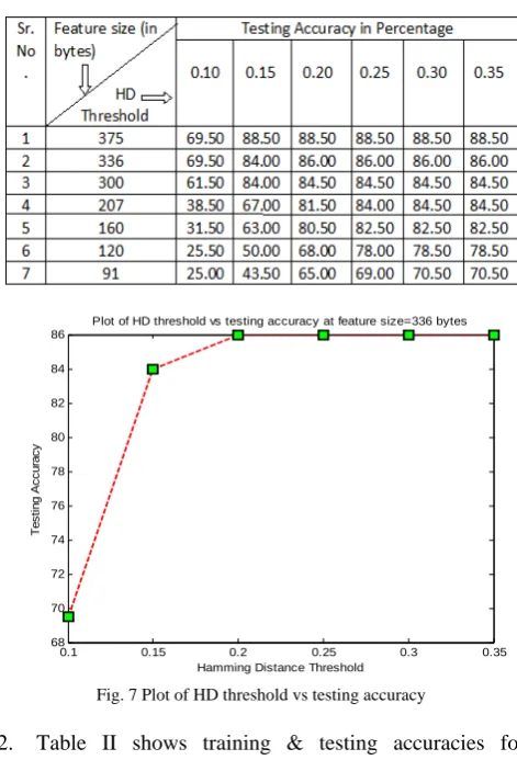
1. Table I shows testing accuracies for different hamming distance threshold values such as 0.10, 0.15, 0.20, 0.25, 0.30 & 0.35, etc as well as for different feature sizes.
From this table, we get to know that for any feature size, as hamming distance threshold value increases, testing accuracy also increases. Also from fig. 7, we can observe that above 0.20 HD threshold value, testing accuracy remains same at its maximum value. Hence 0.20 threshold value is optimum threshold for identification purpose.
TABLEI
ACCURACY TABLE
0.1 0.15 0.2 0.25 0.3 0.35
68 70 72 74 76 78 80 82 84 86
T
e
stin
g
A
ccu
ra
cy
Hamming Distance Threshold
Plot of HD threshold vs testing accuracy at feature size=336 bytes
Fig. 7 Plot of HD threshold vs testing accuracy
2. Table II shows training & testing accuracies for different feature sizes such as 375, 336, 300, 207, 160, 120 & 91 bytes. The hamming distance threshold is kept as 0.20. Training accuracy is 100% for all feature sizes. When same train image is passed through the system, the hamming distance value is always 0.00. The fig. 8 shows that as feature size goes on increasing testing accuracy also increases.
TABLEIII
50 100 150 200 250 300 350 400 55
60 65 70 75 80
T
e
s
ti
n
g
Accu
ra
cy
Feature size
Plot of Feature size Vs Accuracy having HD threshold=0.20 for 120 persons
Fig. 8 Plot of feature size vs accuracy having HD threshold=0.20 for 120 persons
3. As shown in table III, as the number of stages increases, testing accuracy increases & also the feature size decreases. Also, the time required to compute filter coefficients & to perform matching takes less time as number of stages increases.
TABLEIIIII
ACCURACY TABLE
4. FAR is the probability that a non-authorized person is identified. FRR is the probability that an authorized person is not identified; FIR (False Identification rate) is the probability that an authorized person is identified but is assigned to false id value. A perfect biometric authentication system would have a FRR = 0 and a FAR = 0 which is a little bit unachievable in reality. From table IV, we may able to know that feature size varying between 207-300 bytes gives best matching results.
TABLEIVV
ACCURACY TABLE
5. The designed system provides best results for approximate ROI co-ordinates: radii of pupil=100 & radii of iris = 240.
V. CONCLUSIONS
In this paper, an image processing approach for iris feature code generation using dual-tree complex wavelet transform has been implemented. For left & right eye images of the same person, this system is giving up to 92.25% of mismatch results that represents good measure for biometric identification. Experimental results showed that the above algorithm based on DTCWT have demonstrated the effectiveness of the proposed method in terms of improving the recognition rate as compared older methods. Inherent shift invariance is the added advantage of this method. This shows that our approach is promising to improve iris based identification.
REFERENCES
[1] Mohammed A. M. Abdullah, F. H. A. Dulaimi, Waleed Al-Nuaimy, Ali Al-Ataby, “Smart card with iris recognition for high security access environment”, 978-1-4244-7000-6/11, IEEE 2011. [2] A. S. Narote, S. P. Narote, L. M. Waghmare and M. B. Kokare,
“Robust iris feature extraction using dual tree complex wavelet transform,” 2007, IEEE International Conference on Signal Processing and Communications (ICSPC 2007), 24-27 November 2007, Dubai, United Arab Emirates.
[3] J. Daugman, “How Iris Recognition Works”, IEEE Transactions on Circuits and Systems for Video Technology, vol. 14, no. 1, pp. 21-30, 2004.
[4] G. Annapoorani, R. Krishnamoorthi, P. Gifty Jeya, S. Petchiammal@Sudha, “Accurate and Fast Iris Segmentation”, G. AnnaPoorani et al. / International Journal of Engineering Science and Technology, Vol. 2(6), 2010, 1492-1499.
[5] L Cohen, “Time-Frequency Distributions- A Review”, Proc. of IEEE, 77(7), 941-981, 1989.
[6] J B Allen, and L R Rabinar, “A Unified Approach to Short-Time Fourier Analysis and Synthesis”, Proc. IEEE, 65, 1558-1564, 1977. [7] O Rioul, and M Vetterli, “Wavelets and Signal Processing”, IEEE
Sig. Proc. Mag., 14-38, 1991.
[8] I Daubechies, “The Wavelet Transform, Time-Frequency Localization and Signal Analysis”, IEEE Trans. Info. Theory, 36, 961-1005, 1990.
[9] G Strang, and T Nguyen, “Wavelets and Filter Banks”, Wellesley-Cambridge Press, 1996.
[10] G Kaiser, “A Friendly Guide to Wavelets”, Birkhauser, Boston, 1994.
[11] M C Morrone, and D C Burr, “Feature Detection in Human Vision: A Phase Dependent Energy Model”, Proc. R. Soc. Lond., B 235, 221, 1988.
[12] Waheeda Almayyan , Hala S. Own, Hussein Zedan, “Iris Features Extraction using Dual-Tree Complex Wavelet Transform,” International Conference of Soft Computing and Pattern Recognition 2010.
[13] Ivan W. Selesnick, Richard G. Baraniuk, and Nick G. Kingsbury, “The Dual-Tree Complex Wavelet Transform,” IEEE Signal processing magzine, pp.: 123-152, November 2005.
[14] Rajesh M. Bodade, Dr. Sanjay N. Talbar, “Iris Recognition using Combination of Dual Tree Rotated Complex Wavelet and Dual Tree Complex Wavelet,”IEEE ICC 2009 proceedings.