Conference Chair:Prof.Dr.G.ManojSomeswar, Director General, Global Research Academy, Hyderabad,
A Novel Architecture for Integrating Cloud Database Services
with Data Confidentiality and Concurrent Operations Execution
on Encrypted Data
Goinaka Kishor
1; Mr.B.Madhav Rao
2&Prof.Dr.G.Manoj Someswar
3 1M.Tech.(CSE) from Narasimha Reddy Engineering College, Affiliated to JNTUH, Hyderabad, Telangana,
India
2
M.Tech. (CSE), Assistant Professor, Department of CSE, Narasimha Reddy Engineering College,
Affiliated to JNTUH, Hyderabad, Telangana, India
3
B.Tech., M.S.(USA), M.C.A., Ph.D., Principal & Professor, Department Of CSE, Anwar-ul-uloom
College of Engineering & Technology, Affiliated to JNTUH, Vikarabad, Telangana, India
ABSTRACT:
Placing critical data in the hands of a cloud provider should come with the guarantee of security and availability for data at rest, in motion, and in use. Several alternatives exist for storage services, while data confidentiality solutions for the database as a service paradigm are still immature. We propose a novel architecture that integrates cloud database services with data confidentiality and the possibility of executing concurrent operations on encrypted data. This is the first solution supporting geographically distributed clients to connect directly to an encrypted cloud database, and to execute concurrent and independent operations including those modifying the database structure. The proposed architecture has the further advantage of eliminating intermediate proxies that limit the elasticity, availability, and scalability properties that are intrinsic in cloud-based solutions. The efficacy of the proposed architecture is evaluated through theoretical analyses and extensive experimental results based on a prototype implementation subject to the TPC-C standard benchmark for different numbers of clients and network latencies.
KEYWORDS: Infrastructure-as-a-Service (IaaS); Platform-as-a-Service (PaaS); and Software-as-a-Service (SaaS);
Fork-Join-Causal consistency (FJC)
INTRODUCTION
Cloud computing is the use of computing
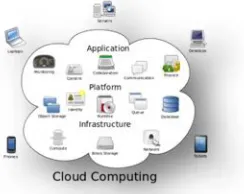
resources (hardware and software) that are delivered as a service over a network (typically the Internet). The name comes from the common use of a cloud-shaped symbol as an abstraction for the complex infrastructure it contains in system diagrams. Cloud computing entrusts remote services with a user's data, software and computation. Cloud computing consists of hardware and software resources made available on the Internet as managed third-party services. These services typically provide access to advanced software applications and high-end networks of server computers.[1]
Figure 1: Structure of cloud computing
The goal of cloud computing is to apply
traditional supercomputing, or high-performance
Conference Chair:Prof.Dr.G.ManojSomeswar, Director General, Global Research Academy, Hyderabad, data storage or to power large, immersive computer
games.[2]
The cloud computing uses networks of large groups
of servers typically running low-cost consumer PC
technology with specialized connections to spread data-processing chores across them. This shared IT infrastructure contains large pools of systems that are linked together. Often, virtualization techniques are used to maximize the power of cloud computing.[3]
Characteristics and Services Models: The
salient characteristics of cloud computing based on the definitions provided by the National Institute of Standards and Terminology (NIST) are outlined below:
On-demand self-service: A consumer can
unilaterally provision computing capabilities, such as server time and network storage, as needed automatically without requiring human interaction with each service’s provider.
Broad network access: Capabilities are available
over the network and accessed through standard mechanisms that promote use by heterogeneous thin or thick client platforms (e.g., mobile phones, laptops, and PDAs).
Resource pooling: The provider’s computing
resources are pooled to serve multiple consumers using a multi-tenant model, with different physical and virtual resources dynamically assigned and reassigned according to consumer demand. There is a sense of location-independence in that the customer generally has no control or knowledge over the exact location of the provided resources but may be able to specify location at a higher level of abstraction (e.g., country, state, or data center). Examples of resources include storage, processing, memory, network bandwidth, and virtual machines. [4]
Rapid elasticity: Capabilities can be rapidly and
elastically provisioned, in some cases automatically, to quickly scale out and rapidly released to quickly scale in. To the consumer, the capabilities available for provisioning often appear to be unlimited and can be purchased in any quantity at any time.
Measured service: Cloud systems automatically
control and optimize resource use by leveraging a metering capability at some level of abstraction
appropriate to the type of service (e.g., storage, processing, bandwidth, and active user accounts). Resource usage can be managed, controlled, and reported providing transparency for both the provider and consumer of the utilized service.[5]
Figure 2: Characteristics of cloud computing Services Models:
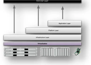
Cloud Computing comprises three different service models, namely Infrastructure-as-a-Service (IaaS), Platform-as-a-Service (PaaS), and Software-Platform-as-a-Service (SaaS). The three service models or layer are completed by an end user layer that encapsulates the end user perspective on cloud services. The model is shown in figure below. If a cloud user accesses services on the infrastructure layer, for instance, she can run her own applications on the resources of a cloud infrastructure and remain responsible for the support, maintenance, and security of these applications herself. If she accesses a service on the application layer, these tasks are normally taken care of by the cloud service provider.[6]
Figure 3: Structure of service models Benefits of cloud computing:
1. Achieve economies of scale – increase volume
Conference Chair:Prof.Dr.G.ManojSomeswar, Director General, Global Research Academy, Hyderabad,
2. Reduce spending on technology
infrastructure. Maintain easy access to your
information with minimal upfront spending. Pay as you go (weekly, quarterly or yearly), based on demand.
3. Globalize your workforce on the cheap.
People worldwide can access the cloud, provided they have an Internet connection.
4. Streamline processes. Get more work done in
less time with less people.
5. Reduce capital costs. There’s no need to spend
big money on hardware, software or licensing fees.
6. Improve accessibility. You have access anytime,
anywhere, making your life so much easier!
7. Monitor projects more effectively. Stay within
budget and ahead of completion cycle times.
8. Less personnel training is needed. It takes
fewer people to do more work on a cloud, with a minimal learning curve on hardware and software issues.
9. Minimize licensing new software. Stretch and
grow without the need to buy expensive software licenses or programs.
10. Improve flexibility. You can change direction
without serious “people” or “financial” issues at stake. [7]
Advantages:
1. Price: Pay for only the resources used.
2. Security: Cloud instances are isolated in the
network from other instances for improved security.
3. Performance: Instances can be added instantly for
improved performance. Clients have access to the total resources of the Cloud’s core hardware.
4. Scalability: Auto-deploy cloud instances when
needed.
5. Uptime: Uses multiple servers for maximum
redundancies. In case of server failure, instances can be automatically created on another server.
6. Control: Able to login from any location. Server
snapshot and a software library lets you deploy custom instances.
7. Traffic: Deals with spike in traffic with quick
deployment of additional instances to handle the load.[8]
LITERATURE SURVEY
Cloud computing can and does mean different things to different people. The common characteristics most interpretations share are on-demand scalability of highly available and reliable pooled computing resources, secure access to metered services from nearly anywhere, and displacement of data and services from inside to outside the organization.[9] While aspects of these characteristics have been realized to a certain extent, cloud computing remains a work in progress. This publication provides an overview of the security and privacy challenges pertinent to public cloud computing and points out considerations organizations should take when outsourcing data, applications, and infrastructure to a public cloud environment.[10]
This article describes the design, implementation, and evaluation of Depot, a cloud storage system that minimizes trust assumptions. Depot tolerates buggy or malicious behavior by any number of clients or servers, yet it provides safety and liveness guarantees to correct clients. Depot provides these guarantees using a two-layer architecture. First, Depot ensures that the updates observed by correct nodes are consistently ordered under Fork-Join-Causal consistency (FJC). FJC is a slight weakening of causal consistency that can be both safe and live despite faulty nodes. Second, Depot implements protocols that use this consistent ordering of updates to provide other desirable consistency, staleness, durability, and recovery properties. Our evaluation suggests that the costs of these guarantees are modest and that Depot can tolerate faults and maintain good availability, latency, overhead, and staleness even when significant faults occur.[11]
We explore a novel paradigm for data management in which a third party service provider hosts "database as a
service", providing its customers with seamless
Conference Chair:Prof.Dr.G.ManojSomeswar, Director General, Global Research Academy, Hyderabad, management as a service, thereby freeing them to
concentrate on their core businesses. Among the primary challenges introduced by "database as a service" are the additional overhead of remote access to data, an infrastructure to guarantee data privacy, and user interface design for such a service.[12] These issues are investigated. We identify data privacy as a particularly vital problem and propose alternative solutions based on data encryption. The paper is meant as a challenge for the database community to explore a rich set of research issues that arise in developing such a service.[13]
We propose a fully homomorphic encryption scheme -- i.e., a scheme that allows one to evaluate circuits over encrypted data without being able to decrypt. Our solution comes in three steps. First, we provide a general result -- that, to construct an encryption scheme that permits evaluation of arbitrary circuits, it suffices to construct an encryption scheme that can evaluate (slightly augmented versions of) its own decryption circuit; we call a scheme that can evaluate its (augmented) decryption circuit bootstrappable.
Next, we describe a public key encryption scheme using ideal lattices that is almost bootstrappable.
Lattice-based cryptosystems typically have decryption algorithms with low circuit complexity, often dominated by an inner product computation that is in NC1. Also, ideal
lattices provide both additive and multiplicative
homomorphisms (modulo a public-key ideal in a polynomial ring that is represented as a lattice), as needed to evaluate general circuits.
Unfortunately, our initial scheme is not quite
bootstrappable -- i.e., the depth that the scheme can correctly evaluate can be logarithmic in the lattice dimension, just like the depth of the decryption circuit, but the latter is greater than the former. In the final step, we show how to modify the scheme to reduce the depth of the decryption circuit, and thereby obtain a bootstrappable encryption scheme, without reducing the depth that the scheme can evaluate. Abstractly, we accomplish this by enabling the encrypter to start the decryption process, leaving less work for the decrypter, much like the server leaves less work for the decrypter in a server-aided cryptosystem.[14]
Rapid advances in networking and Internet technologies have fueled the emergence of the "software as a service"
model for enterprise computing. Successful examples of commercially viable software services include rent-a-spreadsheet, electronic mail services, general storage services, disaster protection services. "Database as a Service" model provides users power to create, store, modify, and retrieve data from anywhere in the world, as long as they have access to the Internet. It introduces several challenges, an important issue being data privacy. It is in this context that we specifically address the issue of data privacy.[15]
SYSTEM STUDY FEASIBILITY STUDY
The feasibility of the project is analyzed in this phase and business proposal is put forth with a very general plan for the project and some cost estimates. During system analysis the feasibility study of the proposed system is to be carried out. This is to ensure that the proposed system is not a burden to the company. For feasibility analysis, some understanding of the major requirements for the system is essential.
Three key considerations involved in the feasibility analysis are
ECONOMICAL FEASIBILITY
TECHNICAL FEASIBILITY
SOCIAL FEASIBILITY
ECONOMICAL FEASIBILITY
This study is carried out to check the economic impact that the system will have on the organization. The amount of fund that the company can pour into the research and development of the system is limited. The expenditures must be justified. Thus the developed system as well within the budget and this was achieved because most of the technologies used are freely available. Only the customized products had to be purchased.
TECHNICAL FEASIBILITY
Conference Chair:Prof.Dr.G.ManojSomeswar, Director General, Global Research Academy, Hyderabad,
SOCIAL FEASIBILITY
The aspect of study is to check the level of acceptance of the system by the user. This includes the process of training the user to use the system efficiently. The user must not feel threatened by the system, instead must accept it as a necessity. The level of acceptance by the users solely depends on the methods that are employed to educate the user about the system and to make him familiar with it. His level of confidence must be raised so that he is also able to make some constructive criticism, which is welcomed, as he is the final user of the system.
SYSTEM DESIGN SYSTEM ARCHITECTURE:
Figure 4: System Architecture DATA FLOW DIAGRAM:
1. The DFD is also called as bubble chart. It is a simple graphical formalism that can be used to represent a system in terms of input data to the system, various processing carried out on this data, and the output data is generated by this system. 2. The data flow diagram (DFD) is one of the most
important modeling tools. It is used to model the system components. These components are the system process, the data used by the process, an external entity that interacts with the system and the information flows in the system.
3. DFD shows how the information moves through the
system and how it is modified by a series of transformations. It is a graphical technique that depicts information flow and the transformations that are applied as data moves from input to output.
4. DFD is also known as bubble chart. A DFD may be
used to represent a system at any level of abstraction. DFD may be partitioned into levels that
represent increasing information flow and functional detail.
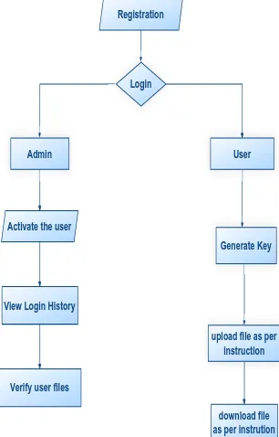
View Login History Activate the user
Verify user files
Registration
Admin
Login
User
Generate Key
download file as per instrution upload file as per instruction
Figure 5: Data Flow Diagram UML DIAGRAMS
UML stands for Unified Modeling Language. UML is a standardized general-purpose modeling language in the field of object-oriented software engineering. The standard is managed, and was created by, the Object Management Group.
The goal is for UML to become a common language for creating models of object oriented computer software. In its current form UML is comprised of two major components: a Meta-model and a notation. In the future, some form of method or process may also be added to; or associated with, UML.
The Unified Modeling Language is a standard language for specifying, Visualization, Constructing and documenting the artifacts of software system, as well as for business modeling and other non-software systems.
The UML represents a collection of best engineering practices that have proven successful in the modeling of large and complex systems.
Conference Chair:Prof.Dr.G.ManojSomeswar, Director General, Global Research Academy, Hyderabad, process. The UML uses mostly graphical notations to express
the design of software projects.
GOALS:
The Primary goals in the design of the UML are as follows:
1. Provide users a ready-to-use, expressive visual
modeling Language so that they can develop and exchange meaningful models.
2. Provide extendibility and specialization mechanisms
to extend the core concepts.
3. Be independent of particular programming
languages and development process.
4. Provide a formal basis for understanding the
modeling language.
5. Encourage the growth of OO tools market.
6. Support higher level development concepts such as
collaborations, frameworks, patterns and
components.
7. Integrate best practices.
USE CASE DIAGRAM:
A use case diagram in the Unified Modeling Language (UML) is a type of behavioral diagram defined by and created from a Use-case analysis. Its purpose is to present a graphical overview of the functionality provided by a system in terms of actors, their goals (represented as use cases), and any dependencies between those use cases. The main purpose of a use case diagram is to show what system functions are performed for which actor. Roles of the actors in the system can be depicted.
User
Registration
Decrypt, Read and Download Activate the User
Admin
View Login History
View Owner FIles File Encrypt and Upload
Generate secretKey get password
verifyuser files
Figure 6: Use Case Diagram
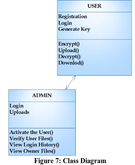
CLASS DIAGRAM:
In software engineering, a class diagram in the Unified Modeling Language (UML) is a type of static structure diagram that describes the structure of a system by showing the system's classes, their attributes, operations (or methods), and the relationships among the classes. It explains which class contains information.
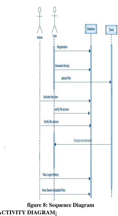
Figure 7: Class Diagram SEQUENCE DIAGRAM:
Conference Chair:Prof.Dr.G.ManojSomeswar, Director General, Global Research Academy, Hyderabad,
Admin
Database
Generate the key User
Registration
Activate the User
View Login History
View Owner Uploaded Files
Cloud
upload filer
verify file access
Verify file access
V
Decrypt and download
figure 8: Sequence Diagram
ACTIVITY DIAGRAM:
Activity diagrams are graphical representations of workflows of stepwise activities and actions with support for choice, iteration and concurrency. In the Unified Modeling Language, activity diagrams can be used to describe the business and operational step-by-step workflows of components in a system. An activity diagram shows the overall flow of control.
Login
Admin
View Login History
Activate the User Generate Key
User
Download Verify user Files
upload file
Figure 9: Activity Diagram INPUT DESIGN
Conference Chair:Prof.Dr.G.ManojSomeswar, Director General, Global Research Academy, Hyderabad, controlling the errors, avoiding delay, avoiding extra steps
and keeping the process simple. The input is designed in such a way so that it provides security and ease of use with retaining the privacy. Input Design considered the following things:
What data should be given as input?
How the data should be arranged or coded?
The dialog to guide the operating personnel in providing input.
Methods for preparing input validations and steps
to follow when error occur.
OBJECTIVES
1. Input Design is the process of converting a user-oriented description of the input into a computer-based system. This design is important to avoid errors in the data input process and show the correct direction to the management for getting correct information from the computerized system.
2. It is achieved by creating user-friendly screens for the data entry to handle large volume of data. The goal of designing input is to make data entry easier and to be free from errors. The data entry screen is designed in such a way that all the data manipulates can be performed. It also provides record viewing facilities.
3. When the data is entered it will check for its validity. Data can be entered with the help of screens. Appropriate messages are provided as when needed so that the user will not be in maize of instant. Thus the objective of input design is to create an input layout that is easy to follow
OUTPUT DESIGN
A quality output is one, which meets the requirements of the end user and presents the information clearly. In any system results of processing are communicated to the users and to other system through outputs. In output design it is determined how the information is to be displaced for immediate need and also the hard copy output. It is the most important and direct source information to the user. Efficient and intelligent output design improves the system’s relationship to help user decision-making.
1. Designing computer output should proceed in an organized, well thought out manner; the right output must be developed while ensuring that each output element is designed so that people will find the system can use easily and effectively. When analysis design computer output, they
should Identify the specific output that is needed to meet the requirements.
2. Select methods for presenting information.
3. Create document, report, or other formats that contain information produced by the system.
The output form of an information system should accomplish one or more of the following objectives.
Convey information about past activities, current status or projections of the
Future.
Signal important events, opportunities, problems, or
warnings.
Trigger an action.
Confirm an action.
SYSTEM ANALYSIS
EXISTING SYSTEM:
Original plain data must be accessible only by
trusted parties that do not include cloud providers, intermediaries, and Internet; in any untrusted context, data must be encrypted. Satisfying these goals has different levels of complexity depending on the type of cloud service. There are several solutions ensuring confidentiality for the storage as a service paradigm, while guaranteeing confidentiality in the database as a service (DBaaS) paradigm is still an open research area.
DISADVANTAGES OF EXISTING SYSTEM:
Cannot apply fully homomorphic encryption
schemes because of their excessive computational complexity.
PROPOSED SYSTEM:
We propose a novel architecture that integrates
cloud database services with data confidentiality and the possibility of executing concurrent operations on encrypted data.
This is the first solution supporting geographically distributed clients to connect directly to an encrypted cloud database, and to execute concurrent
and independent operations including those
modifying the database structure.
The proposed architecture has the further advantage
Conference Chair:Prof.Dr.G.ManojSomeswar, Director General, Global Research Academy, Hyderabad,
Secure DBaaS provides several original features that
differentiate it from previous work in the field of security for remote database services.
ADVANTAGES OF PROPOSED SYSTEM:
The proposed architecture does not require
modifications to the cloud database, and it is immediately applicable to existing cloud DBaaS, such as the experimented PostgreSQL Plus Cloud Database, Windows Azure and Xeround .
There are no theoretical and practical limits to extend our solution to other platforms and to include new encryption algorithm.
It guarantees data confidentiality by allowing a cloud database server to execute concurrent SQL
operations (not only read/write, but also
modifications to the database structure) over encrypted data.
It provides the same availability, elasticity, and scalability of the original cloud DBaaS because it does not require any intermediate server.
SYSTEM TESTING
The purpose of testing is to discover errors. Testing is the process of trying to discover every conceivable fault or weakness in a work product. It provides a way to check the functionality of components, sub assemblies, assemblies and/or a finished product It is the process of exercising software with the intent of ensuring that the
Software system meets its requirements and user expectations and does not fail in an unacceptable manner. There are various types of test. Each test type addresses a specific testing requirement.
TYPES OF TESTS Unit testing
Unit testing involves the design of test cases that validate that the internal program logic is functioning properly, and that program inputs produce valid outputs. All decision branches and internal code flow should be validated. It is the testing of individual software units of the application .it is done after the completion of an individual unit before integration. This is a structural testing, that relies on knowledge of its construction and is invasive. Unit tests perform basic tests at component level and test a specific business process, application, and/or system configuration. Unit tests ensure that each unique path of a business process
performs accurately to the documented specifications and contains clearly defined inputs and expected results.
Integration testing
Integration tests are designed to test integrated software components to determine if they actually run as one program. Testing is event driven and is more concerned with the basic outcome of screens or fields. Integration tests demonstrate that although the components were individually satisfaction, as shown by successfully unit testing, the combination of components is correct and consistent. Integration testing is specifically aimed at exposing the problems that arise from the combination of components.
Functional test
Functional tests provide systematic demonstrations that functions tested are available as specified by the business and technical requirements, system documentation, and user manuals.
Functional testing is centered on the following items:
Valid Input : identified classes of valid input must be accepted.
Invalid Input : identified classes of invalid input must be rejected.
Functions : identified functions must be exercised. Output : identified classes of application outputs must be exercised.
Systems/Procedures: interfacing systems or procedures must be invoked.
Organization and preparation of functional tests is focused on requirements, key functions, or special test cases. In addition, systematic coverage pertaining to identify Business process flows; data fields, predefined processes, and successive processes must be considered for testing. Before functional testing is complete, additional tests are identified and the effective value of current tests is determined.
System Test
System testing ensures that the entire integrated software system meets requirements. It tests a configuration to ensure known and predictable results. An example of system testing is the configuration oriented system integration test. System testing is based on process descriptions and flows, emphasizing pre-driven process links and integration points.
White Box Testing
Conference Chair:Prof.Dr.G.ManojSomeswar, Director General, Global Research Academy, Hyderabad, It is purpose. It is used to test areas that cannot be reached
from a black box level.
Black Box Testing
Black Box Testing is testing the software without any knowledge of the inner workings, structure or language of the module being tested. Black box tests, as most other kinds of tests, must be written from a definitive source document, such as specification or requirements document, such as specification or requirements document. It is a testing in which the software under test is treated, as a black box .you cannot “see” into it. The test provides inputs and responds to outputs without considering how the software works.
Unit Testing:
Unit testing is usually conducted as part of a combined code and unit test phase of the software lifecycle, although it is not uncommon for coding and unit testing to be conducted as two distinct phases.
Test strategy and approach
Field testing will be performed manually and functional tests will be written in detail.
Test objectives
All field entries must work properly.
Pages must be activated from the identified link.
The entry screen, messages and responses must not
be delayed.
Features to be tested
Verify that the entries are of the correct format
No duplicate entries should be allowed
All links should take the user to the correct page.
Integration Testing
Software integration testing is the incremental integration testing of two or more integrated software components on a single platform to produce failures caused by interface defects.
The task of the integration test is to check that components or software applications, e.g. components in a software system or – one step up – software applications at the company level – interact without error.
Test Results: All the test cases mentioned above passed
successfully. No defects encountered.
Acceptance Testing
User Acceptance Testing is a critical phase of any project and requires significant participation by the end user.
It also ensures that the system meets the functional requirements.
Test Results: All the test cases mentioned above passed
successfully. No defects encountered.
IMPLEMENTATION MODULES:
1. Setup Phase
2. Meta Data Module
3. Sequential SQL Operations
4. Concurrent SQL Operations
MODULES DESCRIPTION:
Setup Phase:
We describe how to initialize a Secure DBaaS
architecture from a cloud database service acquired by a tenant from a cloud provider.
We assume that the DBA creates the metadata
storage table that at the beginning contains just the database metadata, and not the table metadata.
The DBA populates the database metadata through
the Secure DBaaS client by using randomly generated encryption keys for any combinations of data types and encryption types, and stores them in the metadata storage table after encryption through the master key.
Then, the DBA distributes the master key to the legitimate users. User access control policies are administrated by the DBA through some standard data control language as in any unencrypted database. In the following steps, the DBA creates the tables of the encrypted database.
Meta Data Module:
In this module, we develop Meta data. So our
system does not require a trusted broker or a trusted proxy because tenant data and metadata stored by the cloud database are always encrypted.
In this module, we design such as Tenant data, data
structures, and metadata must be encrypted before exiting from the client.
The information managed by SecureDBaaS includes
Conference Chair:Prof.Dr.G.ManojSomeswar, Director General, Global Research Academy, Hyderabad,
SecureDBaaS clients produce also a set of metadata
consisting of information required to encrypt and decrypt data as well as other administration information. Even metadata are encrypted and stored in the cloud DBaaS.
Sequential SQL Operations:
The first connection of the client with the cloud DBaaS is for authentication purposes. Secure DBaaS relies on standard authentication and authorization mechanisms pro-vided by the original DBMS server. After the authentication, a user interacts with the cloud database through the Secure DBaaS client.
Secure DBaaS analyzes the original operation to
identify which tables are involved and to retrieve their metadata from the cloud database. The metadata are decrypted through the master key and their information is used to translate the original plain SQL into a query that operates on the encrypted database.
Translated operations contain neither plaintext
database (table and column names) nor plaintext tenant data. Nevertheless, they are valid SQL operations that the Secure DBaaS client can issue to the cloud database. Translated operations are then executed by the cloud database over the encrypted tenant data. As there is a one-to-one correspondence between plaintext tables and encrypted tables, it is possible to prevent a trusted database user from accessing or modifying some tenant data by granting limited privileges on some tables.
User privileges can be managed directly by the
untrusted and encrypted cloud database. The results of the translated query that includes encrypted tenant data and metadata are received by the Secure DBaaS client, decrypted, and delivered to the user. The complexity of the translation process depends on the type of SQL statement.
Concurrent SQL Operations:
The support to concurrent execution of SQL
statements issued by multiple independent (and possibly geographically distributed) clients is one of the most important benefits of Secure DBaaS with respect to state-of-the-art solutions.
Our architecture must guarantee consistency among
encrypted tenant data and encrypted metadata because corrupted or out-of-date metadata would prevent clients from decoding encrypted tenant data resulting in permanent data losses.
A thorough analysis of the possible issues and
solutions related to concurrent SQL operations on encrypted tenant data. Here, we remark the importance of distinguishing two classes of statements that are supported by Secure DBaaS: SQL operations not causing modifications to the database structure, such as read, write, and update; operations involving alterations of the database
structure through creation, removal, and
modification of database tables (data definition layer operators)
RESULTS & CONCLUSION
Conference Chair:Prof.Dr.G.ManojSomeswar, Director General, Global Research Academy, Hyderabad,
negligible overhead. Dynamic scenarios
characterized by (possibly) concurrent modifications of the database structure are supported, but at the
price of high computational costs. These
performance results open the space to future improvements that we are investigating.
REFERENCES
[1] M. Armbrust et al., “A View of Cloud Computing,” Comm. of the ACM, vol. 53, no. 4, pp. 50-58, 2010.
[2] W. Jansen and T. Grance, “Guidelines on Security and Privacy in Public Cloud Computing,” Technical Report Special Publication 800-144, NIST, 2011.
[3] A.J. Feldman, W.P. Zeller, M.J. Freedman, and E.W. Felten, “SPORC: Group Collaboration Using Untrusted Cloud Resources,” Proc. Ninth USENIX Conf. Operating Systems Design and Implementation, Oct. 2010.
[4] J. Li, M. Krohn, D. Mazie`res, and D. Shasha, “Secure Untrusted Data Repository (SUNDR),” Proc. Sixth USENIX Conf. Opearting Systems Design and Implementation, Oct. 2004.
[5] P. Mahajan, S. Setty, S. Lee, A. Clement, L. Alvisi, M. Dahlin, and M. Walfish, “Depot: Cloud Storage with Minimal Trust,” ACM Trans. Computer Systems, vol. 29, no. 4, article 12, 2011.
[6] H. Hacigu¨mu¨ s¸, B. Iyer, and S. Mehrotra, “Providing Database as a Service,” Proc. 18th IEEE Int’l Conf. Data Eng., Feb. 2002.
[7] C. Gentry, “Fully Homomorphic Encryption Using Ideal Lattices,” Proc. 41st Ann. ACM Symp. Theory of Computing, May 2009.
[8] R.A. Popa, C.M.S. Redfield, N. Zeldovich, and H. Balakrishnan, “CryptDB: Protecting Confidentiality with Encrypted Query Processing,” Proc. 23rd ACM Symp. Operating Systems Principles, Oct. 2011.
[9] H. Hacigu¨mu¨ s¸, B. Iyer, C. Li, and S. Mehrotra, “Executing SQL over Encrypted Data in the
Database-Service-Provider Model,” Proc. ACM SIGMOD Int’l Conf. Management Data, June 2002.
[10] J. Li and E. Omiecinski, “Efficiency and Security Trade-Off in Supporting Range Queries on Encrypted Databases,” Proc. 19th
Ann. IFIP WG 11.3 Working Conf. Data and Applications Security, Aug. 2005.
[11] E. Mykletun and G. Tsudik, “Aggregation Queries in the Database-as-a-Service Model,” Proc. 20th Ann. IFIP WG 11.3 Working Conf. Data and Applications Security, July/Aug. 2006.
[12] D. Agrawal, A.E. Abbadi, F. Emekci, and A. Metwally, “Database Management as a Service: Challenges and Opportunities,” Proc. 25th IEEE Int’l Conf. Data Eng., Mar.-Apr. 2009.
[13] V. Ganapathy, D. Thomas, T. Feder, H. Garcia-Molina, and R. Motwani, “Distributing Data for Secure Database Services,” Proc. Fourth ACM Int’l Workshop Privacy and Anonymity in the Information Soc., Mar. 2011.
[14] A. Shamir, “How to Share a Secret,” Comm. of the ACM, vol. 22, no. 11, pp. 612-613, 1979.