Blast Impact and Survivability Research Unit (BISRU), Department of Mechanical Engineering, University of Cape Town, South Africa
Abstract. A refined development of the wedge-bar technique [1] for compression tests at intermediate strain rates is presented. The concept uses a wedge mechanism to compress small cylindrical specimens at strain rates in the order of 10 s−1to strains
of up to 0.3. Co-linear elastic impact principles are used to accelerate the actuation mechanism from rest to test speed in under 300µs while maintaining near uniform strain rates for up to 30 ms,i.e. the transient phase of the test is less than 1% of the total test duration. In particular, a new load frame, load cell and sliding anvil designs are presented and shown to significantly reduce the noise generated during testing. Typical dynamic test results for a selection of metals and polymers are reported and compared with quasistatic and split Hopkinson pressure bar results.
1 Introduction
The techniques used to conduct material tests at low strain rates (<1 s−1) and high strain rates (102s−1–104s−1) are well established, with a wealth of associated literature. In general, low strain rate tests are performed using commer-cially available testing machines, typically of the electro-servohydraulic (ESH) or screw driven type, in accordance with authoritative standards [2]. By contrast, testing in the high strain rate regime is less mature and typically carried out on a variety custom built machines. Nevertheless, there is general consensus in the literature regarding the merits of various high strain rate techniques, the most popular being the split Hopkinson pressure bar (SHPB) [3].
The useful strain rate range of a given testing machine depends on the operating principle according to which it is designed. At low strain rates, where inertial effects are negligible, the entire load path of the testing machine is considered to be in quasi-static (QS) equilibrium with the specimen, i.e. the force measured at the load cell, load frame, actuators, etc. of the testing machine is the same as that experienced by the specimen. By contrast, inertial effects are significant at high strain rates and lead to the generation and interaction of stress waves that manifest as load and displacement oscillations. The classical SHPB technique, though it uses stress waves to load a specimen, avoids these difficulties by making use of bars that are long enough to allow the individual stress waves to be separated. Hence, unlike QS machines, a SHPB is never in equilibrium, although the specimen is considered to be in ‘quasi-equilibrium’ if its ‘ring-up’ time is small in comparison with the test duration [3].
Dynamic material testing in the intermediate strain rate (ISR) regime (100s−1–102s−1) presents an interesting challenge to which neither the traditional QS approach nor the classical SHPB technique are well suited. The ISR regime requires a machine that can impose a given loading rate within a fraction of a millisecond and then maintain it at a constant level for several milliseconds
ae-mail:[email protected]
or longer. Conventional ESH machines can achieve the required speeds and load durations, but can only achieve inferior initial loading rates which, even then, tend to cause severe load oscillations. Conversely, a conventional SHPB, while it can rapidly impose a load, cannot maintain the required test duration due to practical limitations to bar lengths. Furthermore, practical striker sizes limit the energy available to deform specimens.
Various approached have been taken to extend the range of the traditional QS and SHPB techniques [1], the most successful of which either attempt to minimize inertia effects in QS type machine by reducing the size and mass of the components in the load path [4], or extend the duration of the SHPB technique by using long bars [5] or accounting for multiple reflections [6]. A common feature of these machines is the use hydraulic and/or pneumatic actuation and control. While these designs have significantly improved the data available in the ISR regime, some problems still remain. In particular, the published data show that the strain rates vary significantly over the duration of a test. The primary reason for this appears to be the relatively slow response times of the actuation systems to transient test conditions, such as the initial acceleration phase of testing and specimen yielding.
The ‘Wedge-bar’ ISR testing technique was introduced by Cloete & Oxtoby [1] to overcome the above mentioned limitations. In this paper, further developments and im-provements of the wedge-bar concept will be presented, along with a selection of material test results on metals and polymers.
2 The wedge-bar ISR tesing concept
A schematic diagram of the layout of the wedge-bar concept is shown in Figure 1. It consists of three bars and a load frame assembly. The three bars are referred to as the striker bar, wedge-bar and stopper bar. The bars are nominally identical except for a shallow wedge machined into the middle third of the wedge-bar. The components of the miniaturized load frame assembly presented by
Fig. 2.Miniaturized load frame assembly [1].
Cloete & Oxtoby are shown in Figure 2. It consists of the wedge-bar, load frame, sliding anvil and backing plate. A small cylinderical specimen is positioned between the sliding anvil and load frame. The lower surface of the sliding anvil is machined to the same angle as the wedge section of the wedge-bar. The components of the load frame assembly are aligned by means of the surface and machined slot of the backing plate.
To perform a test, the striker is fired from a gas gun at the desired test velocity and impacts upon the wedge-bar. Since the striker and wedge-bar are almost identical, all the momentum is transferred to the wedge-bar after one stress wave reflection, i.e. the striker comes to rest while the wedge-bar proceeds at the desired test velocity. Thereafter, the wedge bar moves through the load frame assembly, forcing the sliding anvil and the lower portion of the load frame apart, thus compressing the specimen between the anvil and the upper portion of the load frame. Finally, the motion of the wedge-bar is arrested through elastic impact with the stopper bar, the position of which determines the stroke of the wedge-bar and hence the final strain of the specimen.
The wedge-bar concept has several features that make it suited to the ISR regime. The use of a wedge mecha-nism allows for a short load path that can rapidly attain equilibrium. This is enhanced by the absence of load path components with large mass or low stiffness, such as pistons and hydraulic fluid. Furthermore, the mechanical advantage of the shallow wedge allows large forces to be generated, while also providing a dramatic speed reduction between the wedge-bar and the sliding platform. The latter is feature is crucial because it allows the energy stored in the wedge-bar can be many times greater than that required to deform the specimen, thus ensuring a near constant rate of deformation.
-0.5 0 0.5 1 1.5
-5 5 15 25 35 45
time [ms]
load frame signal [v] raw data
smoothed data
Fig. 3.Typical miniaturized load frame force data [1].
Another important design feature is the implementa-tion of the wedge mechanism in the form of long bar. This facilitates the use of co-linear elastic impact principles to accelerate and decelerate the wedge-bar. The result is that these phases of the wedge bar motion are accurately controlled and typically take up less than 1% of the overall test duration. This allows for early specimen respose char-acteristics, such as yield, to be captures at the desired strain rate. Furthermore, the technique provides for convenient specimen recovery with a well defined strain rate history.
3 Wedge-bar concept modifications
While most of the above mentioned features were evident in the results reported by Cloete & Oxtoby, two aspects of their design required further attention. The force signal from the miniaturized load frame contained excessive noise, as shown in Figure 3, and a continuous record of the wedge-bar position was not available.
A new load frame design was developed to address the excessive noise in the force signal, as shown in Figures 4 and 5. In contrast to the miniaturized load frame design, the new load frame is much larger than required merely to sustain the compressive force during a test. The design is intended to supress load path vibrations by increasing the inertia of load frame while preserving the short load path of the miniaturized load frame. Furthermore, the load frame geometry is simplified so as to avoid regions where rapid stress wave oscillations can occur and for this reason new design is refered to the monolithic load frame.
Fig. 4.Monolithic load frame assembly.
Fig. 5.Sectioned view of the monolithic load frame assembly.
Further modifications to the load frame assembly in-clude the development of a new high speed load cell, the details of which are provided by Stander [8], and the redesign of the sliding platform to place its centre of mass directly below the specimen.
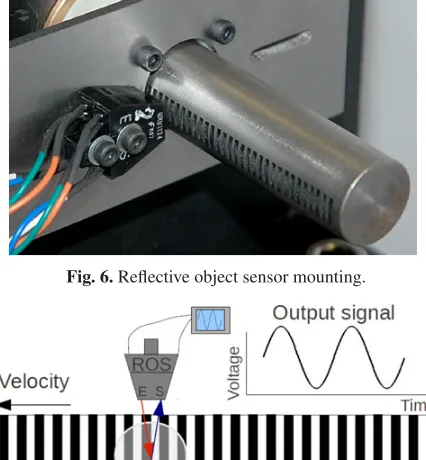
In addition to the load path modifications, a system was developed to capture a continuous record of the wedge-bar position from which the strain rate history of a test can be inferred. The system is based on a reflective object sensor (ROS) which is used to detect the passage of a series of 2 mm grooves machined into the wedge bar, as shown in Figure 6. As the grooves pass below the ROS, the signal oscillates is a sinusoidal pattern, as depicted schematically in Figure 7. By counting the peaks of the signal, the instantaneous position of the wedge-bar can be determined, and hence, due to the shallow wedge angle, the displacement of the specimen can be inferred with great accuracy.
4 Experimental details
Intermediate strain rate test were conducted on annealed aluminium, annealed mild steel, Nylon and poly(methyl methacrylate) (PMMA). All the ISR specimens had a nominal diameter and length of 5 mm. The bars were made
Fig. 6.Reflective object sensor mounting.
Fig. 7. Schemtic diagram of the signal generated by series of grooves passing below a reflective object sensor.
from silver steel with density of 7938 kg m−3and an elastic wave speed of 5143 ms−1. The length of the wedge-bar used in this work was 1.5 m, with a 0.5 m central wedge with an slope of 2:500. With striker velocities in the order of 10 ms−1, these experimental parameters would result in nominal strain rates of approximately 8 s−1.
The length of the wedge allows for a maximum test du-ration of 50 ms at a strain rate of 8 s−1, although durations of between 20 ms and 30 ms were typically used. The time required for a specific point along the wedge-bar to attain the test velocity depends on its position and the time delay between in passage of the initial compression stress wave and the reflected tensile wave. For a 1.5 m wedge-bar the longest delay of 600µs occurs at the striker impact end. However, the portion of the wedge bar initially in contact with the sliding anvil is only 0.5 m from the free end of the wedge-bar and thus attains the test speed in approximately 200µs. In other words, the sliding anvil attains the nominal test speed within 1% of the overall test time.
Two diametrically opposed foil strain gauges (2 mm, 120Ω) were bonded to the load cell, which was made from stainless steel. The signals were amplified using custom built amplifiers (gain of 1000, bandwidth of 100 kHz) and digitized using an ADLINK PCI-9812 card (10 MHz, 12 bit). The force signal was sampled 1 MHz to ensure that no attenuation of the signal occurred and that any noise due to the response of the load frame assembly would be detected.
5 Experimental results
Fig. 8.Typical raw data for an annealed aluminium test obtained using the monolithic load frame assembly.
Fig. 9. Typical processed data for an annealed aluminium test obtained using the monolithic load frame assembly.
in Figure 8. The aluminium is identical to that used by Cloete & Oxtoby and can therefore be compared to the raw data given in Figure 3. It is immediately apparent that monolithic load frame design has achieved its objective of producing a force signal with significantly less the noise than that of the miniaturized load frame.
Figure 9 shows the result of processing the data give in Figure 8. Note that the strain rate is virtually constant for the entire test duration.
The annealed aluminium is know to be relatively strain rate insensitive material and is therefore a useful material with which to verify whether the wedge-bar ISR result is consistent with other testing techniques. Figure 10 compares the ISR aluminium result to tensile QS and SHPB data for the same material. At small strain the wedge-bar data is essentially identical to the QS and SHPB data. This is regarded as confirmation of the validity of the wedge-bar technique. However, at larger strains it begins to deviate upwards do to the effects of friction between the specimen and the faces of the sliding anvil and load cell. This occurred despite the fact that the specimen faces were well lubricated with MoS2grease and indicates that, unlike SHPB testing, there is sufficient time for the lubrication to escape during a test. This indicates that the wedge-bar technique may only be suited to investigating small strain behaviour for volume conserving materials. However, this restriction will not affect the testing of crushable materials,
Fig. 10.Comparison of ISR aluminium results to tensile QS and SHPB data for the same material.
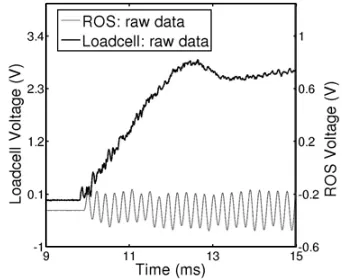
Fig. 11.Typical raw data for an annealed mild steel test obtained using the monolithic load frame assembly.
Fig. 12.Enlargment of the small strain region for an annealed mild steel test using the monolithic load frame assembly.
such as foams. Furthermore, due to its rapid equilibration behaviour, the wedge-bar technique may be ideally suited to the testing of materials that fail at small strains, such as ceramics and bone.
Fig. 13.Annealed mild steel behaviour at various strain rates.
Fig. 14.Effect of strain rate on the yield stress of annealed mild steel.
clearly in Figure 12. The even spacing of the peaks in the ROS signal is indicative of a uniform strain rate. Fur-thermore, unlike some other ISR techniques, the yielding behaviour appears not to affect the strain rate, despite the significant change in the specimen tangent modulus during the yielding process. This can be attributed to the large inherent stiffness of the monolithic load frame assembly and the absence of hydraulic components in the load path. Figure 13 shows the measured response of identical mild steel specimens under various loading conditions. As with the aluminium tests, effect of friction is evident in the latter part of the ISR curve, which consequently diverges from the tensile QS curve and tends toward the SHPB. Nevertheless, the small strain results are considered to be valid. The lower yield stess values show good agreement with published values as shown in Figure 14.
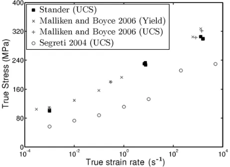
The results from compression tests on Nylon and PMMA in three distinct strain rate regimes are shown in Figures 15 and 16 respectively. The results show that the wedge-bar technique provides good repeatability and gives results that are consistent with the other testing techniques. The strain rate dependence of the yield and ultimate compressive stress (UCS) of Nylon and PMMA are shown in Figures 17 and 18, respectively, along with data ob-tained from the literature. It is apparent that the strength
Fig. 15. Nylon behaviour under compression at various strain rates.
Fig. 16.PMMA behaviour under compression at various strain rates.
properties of Nylon and PMMA are highly variable and depend strongly on process by which they were produced. Nevertheless, the rate dependency of the data is reasonably consistent and suggests that microstructural mechanism that induces strain rate hardening is distinct and indepen-dent from the mechanism that causes strain hardening.
As mentioned previously in Section 1, published in-termediate strain rate data is relatively sparse. This is especially the case for compressive data, as is evident in the data plotted in Figures 17 and 18, where the region between (100s−1–102s−1) has few data points.
6 Conclusions and recommendations
A refined development of the wedge-bar technique [1] for compression tests at intermediate strain rates has been presented. In particular, a new monolithic load frame design was introduced which, along with new load cell and sliding anvil designs, resulted in a significant reduction in the noise generated in the load path during testing. Fur-thermore, a wedge-bar speed sensing system was presented that is based on a reflective object sensor that can detect the passage of grooves machined into the wedge-bar.
Fig. 17.Effect of strain rate on the ultimate compressive stress of Nylon.
Fig. 18.Effect of strain rate on the yield and ultimate compressive stress of PMMA.
poly(methyl methacrylate). The results show good repeata-bility and are consistent with QS and SHPB test results, as well as published data.
At present the wedge-bar technique has been shown to be well suited to testing at strain rates in the order of (10 s−1). However, continued developement and refinement of the wedge-bar technique is in progress with the aim of extended the range of application.
The new wedge-bar configuration combines the rapid equilibration behaviour of the monolithic load frame
ences, Brussels 2009) 249-255
2. Annual book of ASTM standards, 03.01 (ASTM Inter-national, 2007)
3. Gray G.T., Classical Split-Hopkinson Pressure Bar Technique, Report LA-UR-99-2347 (Los Alamos Na-tional Laboratory, 1999)
4. Tarigopula V., Albertini C., Langseth M., Hopper-stad O.S. & Clausen A.H.,DYMAT 2009 (EDP Sci-ences, Brussels 2009) 381-387
5. Gilat A. & Matrka T.A., (EPJ Web of Conferences 6, 2010) 39002
6. Zhao H. & Gary G.,J Mech. Phys. Solids45, (1997) 1185-1202
7. Callister W.D., Materials Science and Engineering: An Introduction, (John Wiley & Sons, New York, 2003)
8. Stander M.,Prototype Development of an Intermedi-ate Strain RIntermedi-ate Compression Testing Machine, (M.Sc. dissertation, University of Cape Town, 2012)
9. Manjoine M.,J Appl. Mech.11, (1944) A211-218 10. Zhao H., Materials Science and Engineering A230,
(1997) 95-99
11. Campbell J.D. & Cooper R.H., Physical basis of Yield and Fracture, (Institute of Physics and Physical Society, London, 1966)
12. Farrokh B. & Khan A.S., European Journal of Me-chanics A/Solids29, (2010) 274-282
13. Khan A.S. & Farrokh B., International Journal of Plasticity22, (2006) 1506-1529
14. Pouriayevali H., Guo Y.B. & Shim V.P.W., Procedia Engineering10, (2011) 2274-2279
15. Mulliken A.D. & Boyce M.C.,International Journal of Solids and Structures43, (2006) 1331-1356 16. Segreti M., Rusinek A. & Klepaczko J.R., Polymer