FULLY AUTOMATIC NUMERICAL SIMULATIONS OF
THREE-DIMENSIONAL CRACK PROPAGATION IN WELDS OF NUCLEAR
COMPONENNTS CONSIDERING MATERIAL HETEROGENEITY
Osamu Hazama1, Seiichi Tajima1, Wenwei Gu1, and Hitoshi Nakamura1
1
Engineer, ITOCHU Techno-Solutions Corporation, Chiyoda-ku, Tokyo, JAPAN ({osamu.hazama, seiichi.tajima, wenweigu, hitoshi.nakamura}@ctc-g.co.jp)
ABSTRACT
We have developed a fully automatic system capable of simulating crack propagation phenomenon in complex three-dimensional geometries. This development was carried out in an attempt to simulate material selective nature of crack growth in welds of nuclear components involving material heterogeneity. The developed software named FINAS/CRACK, automated the cycle of stress analysis, crack propagation, remeshing of a new domain after the growth, and back to stress analysis to realize such simulations. The effectiveness of the new software is illustrated through several numerical samples.
INTRODUCTION
In order to maintain serviceability, structural integrity and safety of mechanical parts and components in nuclear power plants, its service life and current state must always be assessed. Stainless steels and Nickel base alloys have been widely implemented in nuclear components for the characteristics they possess, one of them being weldability. The inclusion of cracks and defects, whether induced initially or by SCC (Stress Corrosion Cracking) and/or fatigue, is becoming an important aspect in the assessment of the integrity of these components ( see e.g. Timbrell et al. (2011)).
Numerical simulations have played a big role in the assessment of the state of the nuclear materials and structures because measurements are not always possible, and high level of safety is expected from the society. In order to determine the growth of defects and its effect on the service life, linear and non-linear fracture mechanics simulations have been extensively carried out in this area. In order to numerically reproduce and assess phenomena involving crack propagation in welds, many cycles of growth evolution incorporating multiple material properties in the weld must be tracked. This process must be automated for it would be impossible to reproduce the complex material selective nature of the growth evolution by human intervention.
tool, to our understanding this can be applied to fracture mechanics in only the linear regime. We believe that incorporation of nonlinear fracture mechanics will be necessary in the future, so this is a shortcoming. ZENCRACK (see e.g. Hou (2001)) is a commercial codes capable of handling crack propagation in three-dimensional geometries. In using ZENCRACK, during the automatic remeshing phase, certain mesh patterns need to be maintained. If the quality of mesh becomes unfit for simulation, then it must be fixed manually, making the system “half” automatic.
In order to track the crack propagation paths to estimate the life of nuclear components, the authors have developed a fully automatic crack propagation simulation software taking into consideration the complex three-dimensional geometries of welds. The software, coined FINAS/CRACK will be introduced and its effectiveness will be illustrated through several numerical examples.
AUTOMATIC CRACK PROPAGATION SYSTEM
System Overview
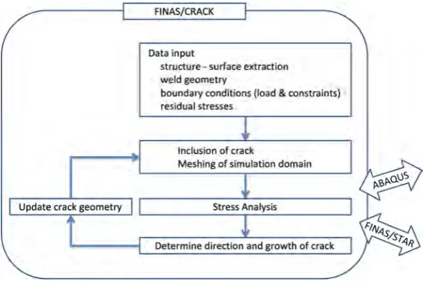
FINAS/CRACK is a fully automatic three-dimensional crack propagation simulation system taking into consideration complex geometries and material heterogeneities. The software is interfaced with commercial codes ABAQUS and FINAS/STAR where the stress analyses are carried out, and fracture mechanics parameters are computed. Receiving the results of the stress analysis, remshing process and the determination of propagation direction is carried out in the developed system. As for the simulations carried out in this study, ABAQUS was used.
As illustrated in Figure 1, the developed system begins by data input. Geometries for the computational domain, crack size and location, etc. are defined. The system is unique, in that minimal input is necessary for carrying out the simulation. After data input, all procedures are carried out automatically. Initial crack is inserted into the model, then it is meshed, computed, and crack growth is estimated. New crack geometry is fed back to the modeler and the domain is remeshed.
Figure 1 Description of system and procedure flow
Computation of Fracture Mechanics Parameters
computing the energy release rate. Considering a tubular region surrounding a small segment of crack front Lc, energy release for a given point s on the crack front in an elastic body with absence of body
forces, inertial and crack face tractions and thermal strains is given by the following (see e.g. Li, Shih and Needleman (1985), Shih, Moran and Nakamura (1986) and Simulia (2011)).
:
Δ
(1)
∙
(2)
In the above equations (1) and (2), W, I, , u, Δas, l and q are the strain energy, identity matrix, stress tensor matrix, displacement vector, magnitude and a vector of virtual extension, and weight function respectively.
Crack-Front Meshing
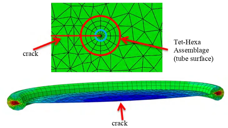
In order to compute fracture mechanics parameters by commercial codes ABAQUS or FINAS/STAR, which implement domain integral form of energy release rate, hexahedral mesh is necessary at the crack front. Therefore, FINAS/CRACK inserts hexahedral mesh in a tubular region along the crack front (Figure 2). The inner most elements (depicted by a blue circle in the figure) are degenerated to wedge elements and the mid-side nodes on the triangular surfaces are arranged in so-called quarter-point nodes to consider 1 √ ⁄ singularity at the crack tip. By incorporating tetrahedral mesh in the structure excluding the crack front, remeshing of the complex three-dimensional geometries is realized.
Figure 2 Meshing at the crack front
Propagation of Cracks under Quasi-Static Conditions crack
Tet-Hexa Assemblage (tube surface)
In the developed system, it is assumed that the crack will propagate in the direction of maximum energy release rate (Hellen and Blackburn (1975)). Figure 3 illustrates the prediction procedure of a given point on the crack front. At a given point, energy release by virtual extension in various directions is computed. A curve is defined through fitting of these values. The angle at which the curve returns maximum value will become the direction of the propagation for this point. This process is repeated for all nodes on the crack front. The magnitude of the growth is calculated by the Paris law or time-dependent laws as shown in equations (3) and (4), respectively.
Figure 3 Prediction of crack growth direction
" #∆%& (3)
' C%& (4)
NUMERICAL EXAMPLES
Cylindrical Bar
A cylindrical bar prescribed tension and torsion is considered. The problem setting is illustrated in Figure 4 (a). The bar is assumed to contain an initial crack as shown in Figure 4 (b) at mid-height (25mm). Mesh without a crack, and location and geometries of the crack are provided by the user as input. Using the input, FINAS/CRACK extracts necessary geometry from the mesh data and inserts the crack. The new geometry including the crack is meshed automatically as well. From here, the cycle of crack propagation procedures are carried out. FINAS/CRACK calls out ABAQUS to carry out stress analyses and computation of fracture mechanics parameters. Using these parameters, angle and growth of the crack is determined. A new geometry taking into consideration the propagated crack is remeshed and the new cycle begins.
Figure 4 Cylindrical bar under tension and torsion
Figure 5 Result of crack propagation in a cylindrical bar
Pipe-Effect of residual stress field on fatigue crack growth
An influence of residual stress on crack propagation is investigated. We trace experiments carried out by Nakamura et al. (1986). A straight pipe specimen of JIS STS42 carbon steel is considered. The outer diameter and inner diameter of the pipe are 265.2mm and 227.2mm, respectively. Crack
(a) Problem setting (b) User provided data
propagation in a stress relieved specimen and two pipes with residual stresses are simulated. The residual stress states considered are illustrated in Figure 6. One involves tension on the inner surface and compression on the outer surface and the other vice versa. The tension and compression are approximately 300 MPa on the inner surface. Semi-elliptical circumferential notch was introduced in the inner surface. For the specifics of the test conditions, readers are directed to Nakamura et al. (1986).
Figure 6 Axial residual stress distribution through the thickness (Nakamura et al. (1986))
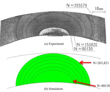
First, crack propagation in the specimen without residual stress was simulated. As an initial crack, first beach mark, not the notch, was used. The depth is 7.8mm and half-length along the major axis is 13.4mm. As for the fatigue growth, following general equation for steel was used (Rolfe and Barsom (1981)).
" 3.6x10./0ΔK2.0 (5)
In the above equation, a is the growth in inches and KI is the stress intensity factor in 34√456ℎ
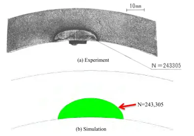
Results are illustrated in Figure 7 and Figure 8 respectively. Figure 7 illustrates the evolution of the crack both by experiment and simulation. For the simulation, the history shown is instant before penetration. Figure 8 illustrates the growth of the crack in the directions of depth and width against load cycles. The experiment and simulation is in good agreement.
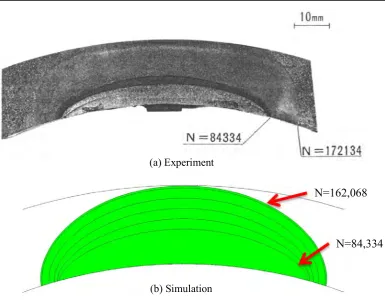
The next case involves a specimen with tensile residual stress on the inner surface. The results are illustrated in Figure 9 and Figure 10, respectively. Again, the FINAS/CRACK software prediction of the crack growth is in good agreement with the experiment.
Figure 7 Propagation history
Figure 8 Load cycles vs. Crack growth (no residual stress)
0 2 4 6 8 10 12 14 16 18 20
0 50,000 100,000 150,000 200,000 250,000 300,000
C
ra
c
k
gr
o
w
th
(m
m
)
Numbers of load cycle
Δa by Experiment
Δc by Experiment
Δa by FINAS/CRACK with ABAQUS
Δc by FINAS/CRACK with ABAQUS
(b) Simulation
N=263,821
N=80130
Figure 9 Propagation history
Figure 10 Load cycles vs. Crack growth (with residual stress)
0 2 4 6 8 10 12 14 16 18 20
0 50,000 100,000 150,000 200,000
C
ra
c
k
gr
o
w
th
(m
m
)
Numbers of load cycle
Δa by Experiment
Δc by Experiment
Δa by FINAS/CRACK with ABAQUS
Δc by FINAS/CRACK with ABAQUS
(a) Experiment
(b) Simulation
N=162,068
Figure 11 Propagation history
CONCLUSION
The authors have developed and introduced a three-dimensional fully automatic software intended for prediction of crack propagation in complex geometries and material heterogeneities. This development was carried out in an attempt to simulate material selective nature of crack growth in welds of nuclear components involving material heterogeneities including welds. The developed software named FINAS/CRACK, automated the cycle of stress analysis, crack propagation, remeshing of a new domain after the growth, and back to stress analysis to realize such simulations. The effectiveness of the new software was illustrated through several numerical samples and more samples including material heterogeneities will be shown at the time of presentation.
REFERENCES
Hellen, T. K. and Blackburn, W. S. (1975). “The calculation of stress intensity factors for combined tensile and shear loading”, Int. J. Fract., 11(4), 605-617.
Hou, J., et al. (2001). “An Evaluation of 3D Crack Growth Using ZENCRACK”, Publicly released internal technical report DSTO-TR-1158.
Kanda, Y. et al. (2009). “A Virtual Crack Closure-Integral Method for Generalized Finite Element with Drilling and Strain Degrees of Freedoms”, J. Comp. Sci. Tech., 3(1), pp. 303-314.
Kaneko S., Okada, H. and Kawai, H. (2012). “Development of Automated Crack Propagation Analysis System (Multiple Cracks and their Coalescence)”, J. Comp. Sci. Tech., 6(3), 97-112.
Kikuchi, M. et al. (2009). “Fatigue Crack Growth Simulation Using S-Version FEM (3rd Report, Fatigure of 3D. Surface Crack)”, Trans. JSME Series A, 75(755), 918-924. (in JAPANESE)
Li, F. Z., Shih, C. F. and Needleman (1985). “A Comparison of Methods for Calculating Energy Release Rates”, Eng. Fract. Mech., 21, 405-421.
(a) Experiment
N=243,305
Nakamura, H., et al. (1986). “FATIGUE CRACK GROWTH UNDER RESIDUAL STRESS FILED IN LOW-CARBON STEEL”, Nucl. Eng. Des., 94, 241-247.
Okada, H., Araki, K. and Kawai, H. (2007). “Stress Intensity Factor Evaluation for Large Scale Finite Element Analyses (Virtual Crack Closure-Integral Method (VCCM) for Mixed Mode/Complex Shaped Crack Using Tetrahedral Finite Element)”, Trans. JSME Series A, 73(733), 997-1004. Rolfe, S. T. and Barsom, J. M. (trans. Yokobori, T. Kawasaki, T. and Watanabe, J.)(1981). FRACTURE
AND FATIGUE CONTROL IN STRUCTURES Applications of Fracture Mechanics, Baifukan, Tokyo, Japan. (in JAPANESE)
Shih, C. F., Moran, B. and Nakamura, T. (1986). “Energy release rate along a three-dimensional crack front in a thermally stressed body”, Int. J. Fract., 30, 79-102.
Simulia (2011), Abaqus 6.11 Theory Manual.