Fabrication of AA6016/ (Al
2
O
3
+AlN) Hybrid Surface
Composite Using Friction Stir Processing
Keerthivel Rajesh.E1, Prem Kumar.N2,Srinath Kumar.S3
First year PG student,Department of Mechanical Engineering, Sri Krishna College of Engineering and Technology,
Coimbatore, Tamil Nadu, India1
First Year PG student, Department of Mechanical Engineering, Sri Krishna College of Engineering and Technology,
Coimbatore, Tamil Nadu, India2
First Year PG student, Department of Mechanical Engineering, Sri Krishna College of Engineering and Technology,
Coimbatore, Tamil Nadu, India3
ABSTRACT: Friction Stir Processing (FSP) is a new solid state processing technique based on the Principle of Friction Stir Welding (FSW) which is used widespread now days for the fabrication of surface composite in metals due to its superior characteristics. Composites are engineered materials made from two or more constituent materials with significantly different physical or chemical properties and which remain separate and distinct on a macroscopic level within the finished structure. The reinforcements impart their special mechanical and physical properties to enhance the matrix properties. Since there is no melting during FSP, problems associated with liquid-solid reactions between reinforcing hard particles and liquid aluminium is eliminated. This makes the FSP a potential process for fabricating Al-MMC’s.
Alumina and Aluminium Nitride powders were mixed in different proportions and packed in the groove made in the aluminium plate. High carbon high chromium tool having cylindrical pin with threaded profile was designed and fabricated. The FSP parameters considered were rotational speed, axial load and tool travelling speed. The plates were then processed and the specimens were prepared from FSPed plates according to the metallurgical standards. The metallurgical properties of processed AMMCs were estimated by conducting optical Microscopy. Microhardness of the specimen is tested using Vickers’s Hardness Machine. Thus the effect of varying the composition of reinforcement material on hardness was studied.
KEYWORDS: Friction stir processing ,Hybrid surface composite, Aluminium alloy
I. INTRODUCTION
FSP has been evolved as the effective solid state processing technique based on the principle of friction stir welding, which uses the heat generated between the tool and work piece. FSP is a method of changing the properties of a metal through intense, localized plastic deformation. Friction stir welding technique was invented at The Welding Institute (Cambridge, UK) in 1991 and developed initially for welding Aluminium alloys. Now it is developed and used for processing metal matrix composites. In this case, a non-consumable rotating tool with pin and shoulder is inserted in a piece of material, for localized micro structural modification for specific property enhancement. Heats produced due to friction makes the metals to reach their plastic state and are stirred by the tool pin. In the last few years, FSP has gained importance in the fabrication industry. The advantages of this process include high reproducibility, short production time and low energy input.
II. SYSTEM MODEL
EXPERIMENTAL PROCEDURE
DEVELOPMENT OF FSP TOOL
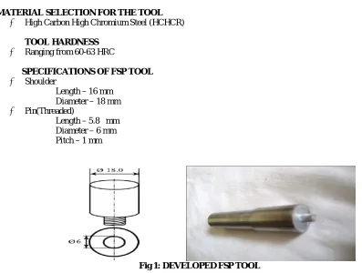
MATERIAL SELECTION FOR THE TOOL
High Carbon High Chromium Steel (HCHCR)
TOOL HARDNESS
Ranging from 60-63 HRC
SPECIFICATIONS OF FSP TOOL
Shoulder
Length – 16 mm Diameter – 18 mm Pin(Threaded)
Length – 5.8 mm Diameter – 6 mm
Pitch – 1 mm
Fig 1: DEVELOPED FSP TOOL
PROCESSING PARAMETERS
There are various parameters that affect the quality of the surface composites in Friction Stir Processing, among them there are four major parameters they are
Method of FSP Tool rotational speed Tool traverse speed Applied force
FSP METHOD
There are various methods by which the Friction Stir Processing can be done, they are (1) reinforcement material as a solvent is made to form a thin coat over the base metal and then FSPed (2) reinforcement material is packed in a groove made in the base metal and covered by another plate of base metal and then FSPed (3) reinforcement material is packed in a groove made in the base metal and the groove is closed by pin less tool and then FSPed.
GROOVE DIMENSIONS
Width – 0.5 mm Depth – 5.5 mm Length – 50 mm
TOOL ROTATIONAL SPEED
The rotation of tool results in stirring and mixing of material around the rotating pin.
coefficient of friction at interface will change with increasing tool rotation rate. Hence the optimum tool rotational speed of 1600 rpm is selected.
TOOL TRAVELLING SPEED
The travelling speed of tool makes the stirred material to move from the front to the back of the pin and finishes process. Higher tool traversing speed is associated with the shorter reaction time and lower reaction temperature. Thus, slower the tool travelling speed, more will be the distribution of the reinforcement material in the base metal. Hence, the optimum tool travelling speed of 60 mm/min is chosen.
APPLIED FORCE
Applied force play an important role in FSP. It is responsible for the forging action developed in the aluminium plates. Thus, the optimum applied force of 8 KN isselected.
FSP OF AA6016 PLATES
The plates are prepared to dimension of 100 mm×50 mm×10 mm. The plates are grooved using wire cut EDM method and five such plates are prepared. Then the ceramic mixtures of different compositions using the formula MASS=DENSITY×VOLUME andare filled in the groove by using filler gauges and numbered as shown in Table as follows.
TABLE % COMPOSITIONS OF CERAMIC MIXTURES
S.NO % OF ALUMINA % OF ALUMINIUM NITRIDE
1 No ceramic particles
2 100% -
3 75% 25%
4 50% 50%
5 25% 75%
6 - 100%
The plates are clamped in the fixtures and are checked for flatness. The edges must not be tilted up after clamping is done. The various parameters of the FSP machine are set .The tool is aligned exactly at the center of the groove and is given automatic feed. First, the groove is closed by using the pin less tool to avoid the spilling out of the ceramic particles from the groove. FSP of aluminium plate is shown in figure 3.4.
Fig 2:FSP OF ALUMINIUM PLATE
Fig 3: TYPICAL FSPed PLATE SHOWING PATH OF TRAVEL
PREPARATION OF THE SPECIMEN
The specimen of dimension 15 mm×50 mm×10 mm is cut from processed plate and it is polished using emery sheets of following grit sizes 220, 280, 320, 400, 600, 800, 1000 and 1200. Then the specimens are wet polished using the diamond pastes of particle sizes 10 microns, 4-5 microns and finally with 0.5 microns. For examining through Optical Microscopy (OM), the specimens have to be etched using KELLER’S REAGENT. It is prepared in a beaker using the following compositions of chemicals.Then the etching is done by immersing the specimen in the beaker containing Keller’s reagent for about 20 secondsand then in water and dried. A typical etched specimen is shown in Fig 3.6.
Fig 4 :TYPICAL ETCHED SPECIMEN
III.RESULTANDDISCUSSION
The FSPed aluminium specimens were subjected to microhardness as well as macro hardness and observed under optical microscope. Results of these observations are discussed in this chapter
EFFECT OF VARYING COMPOSITIONS OF REINFORCEMENT PARTICLES ON PARTICLE DISTRIBUTION (OPTICAL MICROSCOPY)
Optical micrography is observed for the etched specimen at various processed zones. The surface composite layer appears to be very well bonded to the aluminium alloy substrate and no defects are visible at the interface. A narrow thermo mechanically affected zone (TMAZ) is observed. The frictional heat generated by the rotating tool and application of high stresses during FSP lead to stretching of Al2O3 and AlN particles along the shear stress directions.
The size of Al2O3 and AlN particles is not uniform throughout the FSP zone. The nucleation sites are increased with the presence of the reinforcement particles which lead to the reduction of aluminum matrix grain size. Formation of onion rings is one of the desirable characteristics of FSP which is found in optical photomicrograph of FSP zone.
EFFECT OF VARYING COMPOSITIONS OF REINFORCEMENT PARTICLES ON HARDNESS MACROHARDNESS
Macro hardness of the FSPed specimen is taken using Rockwell hardness machine in B scale under the load of 100 Kg with ball of 1/16” inch diameter and the values of the hardness are shown in Table 4.1. Al2O3 and AlN particles enhanced the hardness of aluminium alloy.
TABLE MACROHARDNESS VALUES SPECIMEN
NO
MACROHARDNESS (HRB)
BASE METAL AVERAGE STIR ZONE AVERAGE
1 (FSP OF AA 6016)
B-89 B-87.33 B-91 B-89.33
B-85 B-88
B-88 B-89
3
(75% Al2O3 & 25%
AlN)
B-87 B-87.66 B-93 B-91.33
B-91 B-87
B-85 B-94
4
(50% Al2O3 & 50%
AlN)
B-89 B-87 B-94 B-93
B-87 B-92
B-85 B-93
5
(25% Al2O3 & 75%
AlN)
B-88 B-88 B-89 B-88.66
B-85 B-87
B-91 B-91
It is observed from the table that the hybrid surface composite having equal composition (50% Al2O3 & 50% AlN) exhibit more hardness than the surface composite fabricated using other composition of ceramic particles.
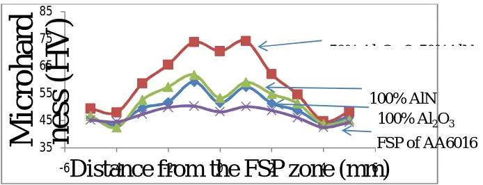
MICROHARDNESS
Fig 6: DISTANCE FROM THE CENTRE OF FSP ZONE VS HARDNESS HV
It is observed from the table that the hybrid surface composite having equal composition (50% Al2O3 & 50% AlN) exhibit more hardness than the surface composite fabricated using other composition of ceramic particles.
35 45 55 65 75 85
-6 -4 -2 0 2 4 6
M
ic
roha
rd
ne
ss
(
H
V
)
Distance from the FSP zone (mm)
50% Al O & 50%AlN
100% Al
2O
3100% AlN
The average hardness of FSP zone is 25 % higher than that of the friction stir processed aluminum alloy. The hardness drops during FSP of aluminum alloy due to dissolution of precipitates.
IV.CONCLUSION
. The following conclusions were arrived from the investigations after analyzing the microstructure and hardness of Friction Stir Processed 6016 plates,
Optical micrography shows that the surface composite layer appears to be very well bonded to the aluminum alloy substrate and no defects are visible at the interface. Also, the grain size of the aluminum alloy is obviously refined by FSP.
For various percentage composition of reinforcement material, it is observed that the hybrid surface composite exhibit more hardness than the surface composite fabricated using single ceramic particle.
REFERENCES
1) R.S. Mishra, M.W. Mahoney, S.X. McFadden, N.A. Mara, and A.K. Mukherjee: Scripta Mater., 2000, vol. 42, pp. 163–68. 2) R.S. Mishra and Z.Y. Ma: Mater. Sci. Eng., R, 2005, vol. 50, pp. 1–78.
3) Z.Y. Ma: Metall. Mater. Trans. A, 2008, vol. 39A, pp. 642–58.
4) P.B. Berbon, W.H. Bingel, R.S. Mishra, C.C. Bampton, and M.W. Mahoney: Scripta Mater., 2001, vol. 44, pp. 61–66. 5) D. Manisha, J.W. Newkirk, and R.S. Mishra: Scripta Mater.,2007, vol. 56, pp. 541–44.
6) A.M.Thomas, C.J. Dawes, M.Gittos and D.Andrews, “Friction Stir? Where we are, and where we are going”, TWI Bulletin, 39 (1998), 44-50. 7) T. Hashimoto, N. Nishikawa, S. Tazaki and M.Enomoto, “Mechanical properties of Joints for Aluminium Alloys with Friction Stir Welding
Process”. Preprints 8) INALCO 98 (7th
Int. Conf. Joints in Aluminium), Cambridge, UK, (1998), 237 – 247.
9) Sassani, F., and Neelam, J. R. 1988. Friction welding of incompatible materials. Welding Journal 67(11): 264-s to 270-s.