Computer-Aided Design of Superconducting Equilateral Triangular
Patch on Anisotropic Substrates
Abdelkarim Gadda1, Sami Bedra1, 2, *, Chahinez Agaba2,
Siham Benkouda3, Randa Bedra1, and Tarek Fortaki1
Abstract—The effects of both anisotropy in the substrates and the superconducting films on
the resonant frequencies and radiation patterns of an equilateral triangular patch are investigated theoretically. Our proposed method is based on the modified cavity model in conjunction with the electromagnetic knowledge. The validity of the proposed method is tested by comparing the computed results of the resonant characteristics with experimental data. Results show effects of the superconducting patch thickness as well as the anisotropy in the substrate on the resonant frequency and the radiation pattern of the triangular patch. The effects of the antenna parameters on resonant frequencies and radiation patterns are also presented and discussed. At higher substrate thicknesses, numerical results indicate that the radiation pattern is drastically changed. The resonant frequency, on the other hand, decreases with high equivalent permittivity of the anisotropic substrate. The proposed method is very fast, simple, and compatible well with CAD.
1. INTRODUCTION
Since the discovery of high-temperature superconductivity (HTS), tremendous technical breakthroughs have been made in the development of these materials and gained the attention of scientists and engineers around the world [1, 2]. A superconducting microstrip antenna was one of the first microwave components demonstrated as an application of high-temperature superconducting material [3, 4]. The primary advantage of using superconducting materials in the development of microstrip antennas is the reduction of ohmic losses associated with the radiator and ancillary feed and matching networks [1]. Another advantage of a high-temperature superconducting microstrip antenna (HTSMA) is the increase in efficiency or gain [4]. Several researchers have often drawn attention to microstrip antennas because of their usefulness in wireless communication, radar systems, and remote sensing applications [3–5]. Due to multiple features, unique and attractive advantages such as low profile, compactness, low weight to handle, low cost, and being able to fabricate on a printed circuit board [1, 7, 8]. Further, they are reliable and available in different shapes and geometries, such as square, rectangular, circular, triangular, annular, and other shapes [9–11]. Lately, triangular patch antennas are among the forms that have attracted a lot of attention [10–14]. Specifically, equilateral triangle patch is generally the most used triangular patch type because it has the property of high quality factor and the advantage of taking up less space than rectangular and circular shapes [14]. It is also suitable for use in a curved surface because of its compatibility [11]. Unfortunately, the standard microstrip antenna has the disadvantage of a limited bandwidth, which limits its applications in several areas [7]. Several useful techniques have been reported to broaden bandwidth of microstrip antennas (MSAs). Firstly, the most popular way to
Received 8 September 2019, Accepted 19 November 2019, Scheduled 27 November 2019
* Corresponding author: Sami Bedra ([email protected]).
1 Laboratory of Advanced Electronics L.E.A, Department of Electronics, University of Mostefa Ben Boula¨ıd-Batna 2, Batna 05000,
enhance bandwidth is the use of an electrically thick substrate, low dielectric constant substrate, and multilayered stacked geometry [1, 15, 16]. However, all of the above techniques increase the size or volume of the antenna. Secondly, cutting slots inside the patch [16] and employing aperture coupled feeding network technique is another way to increasing the bandwidth of microstrip antennas. As compared to simpler coupled designs, slot cut in MSAs is relatively complex in design [7]. Substrate materials useful in Microwave Integrated Circuits (MICs) exhibit a natural or artificial dielectric anisotropy due to their manufacturing process [17]. Isotropic substrates may as well exhibit anisotropy at high frequencies [18]. In earlier studies, we demonstrate that the optical properties of anisotropic substrate can dynamically exhibit wider bandwidth characteristic with several resonant frequencies [15–19]. Therefore, its precise description, including the effect of anisotropy on the substrate, is important for computer-aided design of microstrip antennas. Several methods have been reported to study the properties of resonance and radiation patterns of microstrip patch antennas which utilize various techniques, and generally these techniques are classified as either approximate or full-wave methods [11–16]. Approximate techniques are usually developed for structures of a simple geometry, and furthermore, because they make the problem easy to understand by using certain assumptions, they can be relatively reliable and accurate under relevant conditions [16]. The spectral domain approach, full-wave analysis methods, and also commercially available simulation software can be used for the analysis of characteristics of patch antennas in multilayer substrates and for various structures and complex geometry [17–19]. All of these techniques provide reasonably accurate results. Notwithstanding, these techniques are not suitable for the design oriented interactive computer aided design (CAD) or for the direct synthesis of microstrip antennas due to their complexity and long computational time requirement [11, 20]. In this paper, computer-aided-design based on an accurate model of the cavity method in conjunction with electromagnetic knowledge is presented to analyze the resonance and radiation characteristics of superconducting equilateral patches on isotropic and anisotropic substrates. To the best of our knowledge, the numerical treatment of cavity problem with anisotropic substrates and superconducting equilateral triangular structure is much less written about. All obtained results of the proposed model are compared with the measured and calculated results, to prove the validity and ubiquity of the proposed model. The paper is organized as follows. In Section 2, a detailed cavity model analysis of superconducting equilateral microstrip antenna is provided. Using electromagnetic knowledge to ensure the effects of fringing fields, the anisotropy in the substrate and the superconducting films are accurately included in the formalism of the problem. Section 3 presents and compares the obtained results of an equilateral microstrip antenna on an anisotropic substrate and also discusses the parametric study with the effect of various parameters on the resonance and radiation characteristics of the superconducting equilateral patch antenna. Finally, in Section 4, conclusions are drawn from the obtained results.
2. THEORY
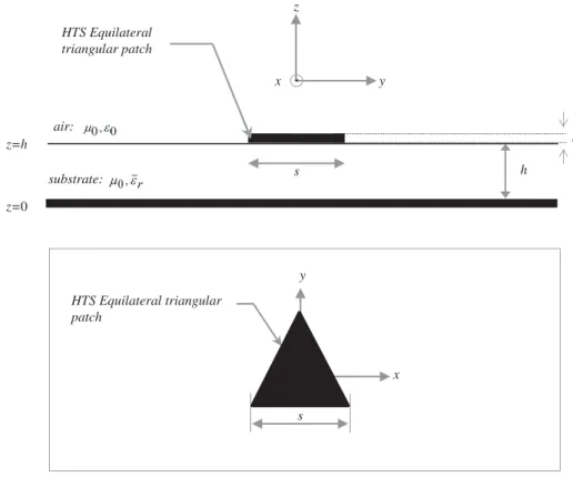
First and foremost, in this section, a formulation of modified cavity model is summarized to calculate the resonant frequency of an equilateral triangular superconducting patch as shown in Figure 1, which is applicable to isotropic as well as anisotropic substrates. TheT csuperconducting equilateral triangular patch of side lengths with thicknesstis printed on a grounded dielectric slab of thickness h.
2.1. Resonant Frequency of Microstrip Antennas
The resonant frequencies for dependent TM modes meet the boundary condition of perfect magnetic wall for the equilateral triangular microstrip patch based on the cavity model theory is given by [21]
fm n= 32υ0
s√εr
m2+ n2+mn (1)
where εr is the permittivity; υ0 is the velocity of the electromagnetic wave in free space; m and nare the order of the diverse resonant modes; andsis the dimension indicated on Figure 1. The fundamental mode of the geometry, described in Figure 1, is chosen by defaultT M01.
z=0
z=h
s
substrate: h
y z
x HTS Equilateral
triangular patch
air:
s y
x HTS Equilateral triangular
patch
t
Figure 1. Side and top views of an equilateral triangular superconducting patch antenna.
proposed to replace the side length sin Eq. (1) with an effective value as follows [22]
seff =s+√hε
r (2)
However, each mode has its own field distribution, and different modes could have different effective side lengths. This requires the development of a formula for the effective side length different from Equation (1). Thus, using curve fitting with the measured values, a new formula is proposed for the effective side length in which the side length varies with the mode indicesm and nas follows [22]
seff =s+ 2 √
m·√h εr −2
√
mn·√h
εr + 197.1·
n h2
s εr (3)
The goal of the second proposition is to improve the calculation of the resonant frequency by using the formula of the effective dielectric constant (effective permittivity), given by [6]
εre = εr2+ 1+εr4−1
1 + 12h
s −1
2
(4)
The substrate material is uniaxially anisotropic with the optical axis being normal to the patch. The uniaxial substrate is characterized by the free-space permeability μ0 and a permittivity tensor of the form [4]
¯
εr=
εx 0 0
0 εx 0 0 0 εz
(5)
In order to account the anisotropy in the substrate by using electromagnetic knowledge, thickness h
parameters using the following equations [6]
εreq = εz (6)
heq = h
εx
εz (7)
2.2. Resonant Frequency of High-Temperature Superconducting Microstrip Antenna
The resonant frequency of HTSMAs will vary with temperature due to changes in the surface reactance of the HTS thin films used to fabricate the microstrip patches. This change in resonant frequency can be determined using a modified cavity model of the microstrip patch antenna, by considering the effective dielectric constant [6].
εeff =εreq
1 + λf
heqcoth
t
λf (8)
where t is the thickness of HTS film, and εeff is the permittivity equivalent. For a homogeneous
superconductor, the temperature dependence of the magnetic penetration depthλf can be modeled by
the Gorter-Casimir two-fluid model as [6]
λf =λ0
1−
T T c
4−12
(9)
whereT is the operating temperature, andT cis the transition temperature of the superconductor film. Although this expression is not empirically correct for HTS films because of their inhomogeneities, it is still useful for modelling the temperature behaviour ofλf for HTS, especially at temperatures far below
T c[23].
3. NUMERICAL RESULTS AND DISCUSSIONS
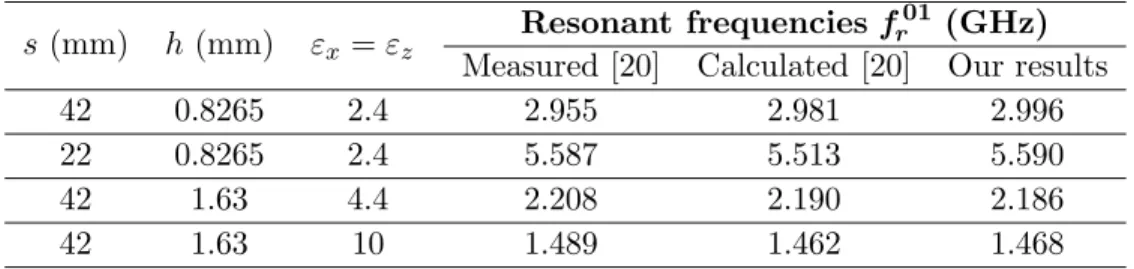
In this section, to verify the accuracy of the proposed model for the equilateral triangular microstrip patch printed on isotropic substrates of two first modes T M01 and T M11, comparisons are illustrated between our numerical results and those measured and calculated using cavity model analysis of equilateral triangular patches of different sizes for different values of constant and thickness substrates [20]. For isotropic substrate, the two components of the relative permittivity are identical i.e., εx =εz. The calculated results shown in Table 1 agree very well with experimental and calculated
results in [20], and the maximum difference between the experimental and our numerical results is less than 1.5%.
Table 1. Comparison of the results of the resonant frequencies with measured data of equilateral
triangular microstrip patch printed on isotropic substrates.
s(mm) h (mm) εx =εz Resonant frequencies f
01
r (GHz)
Measured [20] Calculated [20] Our results
42 0.8265 2.4 2.955 2.981 2.996
22 0.8265 2.4 5.587 5.513 5.590
42 1.63 4.4 2.208 2.190 2.186
42 1.63 10 1.489 1.462 1.468
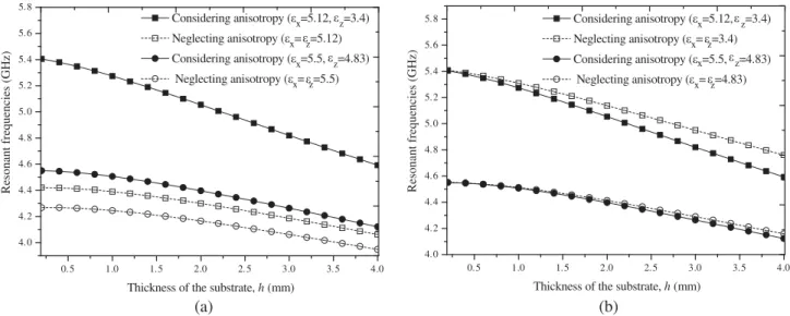
0.5 1.0 1.5 2.0 2.5 3.0 3.5 4.0 4.0
4.2 4.4 4.6 4.8 5.0 5.2 5.4 5.6 5.8
Considering anisotropy (εx=5.12, z=3.4) Neglecting anisotropy (εx=z=5.12) Considering anisotropy (εx=5.5, z=4.83) Neglecting anisotropy (εx=z=5.5)
Resonant frequencies (GHz)
Thickness of the substrate, h (mm) (a)
0.5 1.0 1.5 2.0 2.5 3.0 3.5 4.0 4.0
4.2 4.4 4.6 4.8 5.0 5.2 5.4 5.6
5.8 Considering anisotropy (εx=5.12, z=3.4) Neglecting anisotropy (εx=z=3.4) Considering anisotropy (εx=5.5, z=4.83)
Neglecting anisotropy (εx=z=4.83)
Resonant frequencies (GHz)
Thickness of the substrate, h (mm)
(b) ε
ε ε ε
ε ε
ε ε
Figure 2. Resonant frequency versus the thickness of the substrate (a) whenεz changed, (b) when εx
changed; s= 20 mm.
shows the resonant frequencies of equilateral triangular patch printed on two different iso/anisotropic substrates.
In Figure 2(a), the results obtained for the resonant frequency of the fundamental mode of the triangular patches printed on different anisotropic dielectric substrates are compared with the results that would be obtained if the dielectric anisotropy of the layers were neglected and the layers assumed to be isotropicεx =εz. Note that, in Figure 2(a), the anisotropy is obtained by changingεz while keeping
εxconstant. In this case, it is seen that the resonant frequency decreases monotonically with increasing
substrate thickness. The differences between the results obtained considering dielectric anisotropy and the results obtained neglecting dielectric anisotropy reach 4.5% when the anisotropic dielectric is Boron nitride (εx= 5.12, εz = 3.4) and 10% when the dielectric is Magnesium fluoride (εx = 5.5, εz = 4.83).
When εx varies, and εz remains constant, the resonant frequency decreases with the increases in
substrate thickness as shown in Figure 2(b). The shift value remains almost constant regardless of the value of the substrate thickness. From these figures, we can conclude that the permittivity εz along the optical axis is the most important factor for the determination of the resonance frequency.
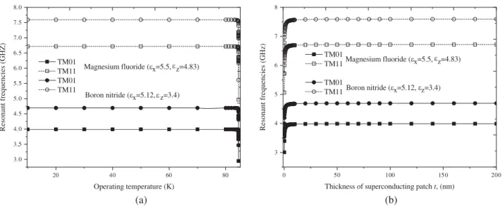
In order to investigate the effects of HTS materials on the resonant characteristics of microstrip antennas, the resonant frequencies of equilateral triangular patch antenna of two different modes as a function of operating temperature and thickness of the superconducting film are illustrate in Figure 3(a) and Figure 3(b), respectively.
In Figure 3(a), we show the relation between the operating temperature (T) and the resonant frequency of two different modes of the equilateral triangular microstrip antenna for two different anisotropic substrate materials. The first anisotropic material is Fluoride of magnesium which has the pair of relative permittivities (εx = 5.5, εz = 4.83) while the second anisotropic material is Boron
nitride (εx = 5.12, εz = 3.4). Each substrate has a thickness of h = 0.826 mm. The side length of
the patch is s = 22 mm fabricated with YBCO (YBa2Cu3O7) superconducting thin film of thickness
t = 330 nm, with a zero-temperature penetration depth (λ0 = 140 nm) and transition temperature
T c= 84.5 K.
From the results of Figure 3(a), it can be seen that increasing the temperature will decrease the resonance frequencies of the two modes (T M01andT M11). This decrease is significant for temperatures close to the transition temperature. These behaviors are very consistent with those reported elsewhere for rectangular and circular shapes [9, 17]. Note that the sudden change in the resonance frequency at temperatures close to the critical temperature (T c) can be attributed to a change in the magnetic penetration depth of YBCO.
20 40 60 80 3.0
3.,5 4.0 4.5 5.0 5.5 6.0 6.5 7.0 7.5 8.0
Boron nitride (εx=5.12, z=3.4) TM01
TM11 TM01 TM11
Resonant frequencies (GHZ)
Operating temperature (K) Magnesium fluoride (εx=5.5, z=4.83)
(a)
0 50 100 15 0 200 3
4 5 6 7 8
Boron nitride (εx=5.12, z=3.4)
Magnesium fluoride (εx=5.5, z=4.83)
TM01 TM11
TM01 TM11
Resonant frequencies (GHz)
Thickness of superconducting patch t, (nm)
(b) ε
ε
ε
ε
Figure 3. (a) Resonant frequency against operating temperature and (b) thickness of the high T c
superconducting triangular patch. The superconducting patch is printed on two different anisotropic substrate materials; s= 22 mm, λ0 = 140 nm,T c= 84.5 K, h= 0.826 mm, t= 330 nm.
on Magnesium fluoride material are lower than those obtained when the superconducting patch is printed on Boron nitride material because the effective relative permittivity of the first material is greater than the second material. The variation of resonant frequency with the thickness of superconducting patch is shown in Figure 3(b). The parameters of the antenna are identical to those used in Figure 3(a). The operating temperature is T = 77 K.
It should be noted that as the thickness of the superconducting patch increases, the resonant frequency increases rapidly until the thickness of the patchtreachesλ0. After this value, increasing the superconducting thickness will slowly increase the resonance frequency of the antennas. In addition, the resonant frequencies of antennas when the superconducting patch printed on Boron nitride are higher than those when the superconducting patch printed on Fluoride de magnesium because of the effective permittivity of the substrate in the former case compared to that in the latter case. In conclusion, the effects of the anisotropic substrate on the resonant frequency of the high T csuperconducting antennas analyzed are stronger and must be considered in the design procedures of the superconducting microstrip structures.
We plot, in Figure 4, the influence of the operating temperature of superconducting patch on the effective permittivity εeff of the anisotropic substrates. Figure 4 shows the results of effective
permittivity as function of the operating temperature of superconducting equilateral microstrip patch with two anisotropic materials using the closed form of the effective permittivity (Equation (8)). The equilateral triangular patch of thickness t = 320 nm with a critical temperature T c = 84.5 K, zero-temperature penetration depth λ0 = 140 nm, and printed on two different anisotropic substrates of thicknessh= 0.826 mm.
We observe that after a sharp initial increase in the operating temperature, the effective per-mittivity is relatively flat and appears around the value of the perper-mittivity along the optical axis for temperature belowT c. The effective permittivity begins to grow and eventually becomes high near crit-ical temperatureT cbecause nearT c, high temperature superconducting materials begin to behave like base metals. As an example, when the operating temperature is varied from T = 80 K to T = 84.5 K, the effective permittivity increases from 3.4 to 4 when the patch is printed on Boron nitride and from 4.84 to 5.60 when the patch is printed on Fluoride of magnesium.
The radiated pattern of an equilateral triangular patch printed on different dielectric substrates for two different thicknesses of substrates for the fundamental modeT M01 are shown in Figure 5.
20 40 60 80 3
4 5 6 7 8
9 Magnesium fluoride (εx=5.5, z=4.83) Boron nitride (εx=5.12, z=3.4)
Effective permittivity
Operating temperature (K) ε ε
Figure 4. Effective permittivity versus operating temperature of superconducting equilateral patch
printed on two anisotropic substrates;T = 77 K,T c= 84.5 K, λ0= 140 nm, h= 0.826 mm.
-90 -60 -30 0 30 60 90 0.0
0.2 0.4 0.6 0.8 1.0
Normalized Radiation patterns
0.826 mm 1.63 mm
0.826 mm 1.63 mm PTFE
Quartz
(a)
-90 -60 -30 0 30 60 90 0.0
0.2 0.4 0.6 0.8 1.0
0.826 mm 1.63 mm
0.826 mm 1.63 mm
Normalized Radiation patterns
PTFE Quartz
(b)
θο θο
Figure 5. Normalized radiation patterns of a superconducting triangular patch printed on two
anisotropic dielectric substrates for the T M01 mode in (a) the plane φ= 0 and (b) the plane φ = π2;
s= 22 mm, (Quartz, d= 0.827 mm, fr = 4.10 GHz), (Quartz, h = 1.63 mm, fr = 3.97 GHz), (PTFE,
d = 0.827 mm, fr = 5.54 GHz), (PTFE, h = 1.63 mm, fr = 5.26 GHz), T = 77 K, T c = 84.5 K,
λ0= 140 nm,t= 320 nm.
superconducting thin film of thickness t = 330 nm, with a zero-temperature penetration depth (λ0 = 140 nm), operating temperature T = 77 K, and transition temperature T c = 84.5 K. The side length of the superconducting patch is s = 22 mm printed on two anisotropic substrates, Quartz (εx = 4.4, εz = 4.6) and PTFE (εx = 2.88, εz = 2.43) of various thicknesses. By comparing the radiation patterns for the cases where the substrate is PTFE and Quartz, it can be concluded that the radiation efficiency is lower for higher dielectric constant along the optical axis (εz), which is in
4. CONCLUSION
In this paper, we have presented an improved CAD model based on modified cavity model in conjunction with electromagnetics knowledge to study resonant characteristics of a superconducting equilateral triangular patch antenna. Original results concerning the effect of the operating temperature on the resonant frequencies and radiation patterns of superconducting microstrip antennas printed on anisotropic substances are presented, with these more precise theoretical results, reduced computation time, and better theory-experiment agreement. The results confirm that in order to predict resonance frequency variations with a permittivity of the anisotropic substrate, it is necessary to consider both the variation ofεxandεz, and not only the ratioεx/εz. Other results obtained show that the dependence of
the resonant frequency is more significant whenεx changes and for high thicknesses of the substrate; for
thin substrates,εz permittivity along the optical axis is the most important factor in determining the
resonant frequency. An increasing gain for the realization of a patch antenna for a specific application is obtained by introducing the superconducting into the geometries of the patch antennas. Finally, this model can serve as a basic element for the design of a conducting an/or superconducting antenna.
REFERENCES
1. Liu, S.-F., X.-W. Shi, and S.-D. Liu, “Study on the impedance-matching technique for high-temperature superconducting microstrip antennas,”Progress In Electromagnetics Research, Vol. 77, 281–284, 2007.
2. Morrow, J. D., J. T. Williams, M. F. Davis, D. L. Licon, H. Rampersad, D. R. Jazdyk, X. Zhang, S. A. Long, and J. C. Wolfe, “Circularly polarized 20-GHz high-temperature superconducting microstrip antenna array,” IEEE Transactions on Applied Superconductivity, Vol. 9, 4725–4732, 1999.
3. Lancaster, M. J., H. Y. Wang, and J.-S. Hong, “Thin-film HTS planar antennas,” IEEE Transactions on Applied Superconductivity, Vol. 8, 168–177, 1998.
4. Bedra, S., R. Bedra, S. Benkouda, and T. Fortaki, “Superstrate loading effects on the resonant characteristics of high Tc superconducting circular patch printed on anisotropic materials,”Physica C: Superconductivity and Its Applications, Vol. 543, 1–7, 2017.
5. Biswas, M. and A. Mandal, “Design and development of an equilateral patch sensor for determination of permittivity of homogeneous dielectric medium,” Microwave and Optical Technology Letters, Vol. 56, 1097–1104, 2014.
6. Bedra, S., R. Bedra, S. Benkouda, and T. Fortaki, “Efficient CAD model to analysis of high T c superconducting circular microstrip antenna on anisotropic substrates,” Advanced Electromagnetics, Vol. 6, 40–45, 2017.
7. Liu, J., S. Zheng, Y. Li, and Y. Long, “Broadband monopolar microstrip patch antenna with shorting vias and coupled ring,”IEEE Antennas and Wireless Propagation Letters, Vol. 13, 39–42, 2013.
8. Sun, C., “A design of compact ultrawideband circularly polarized microstrip patch antenna,”IEEE Transactions on Antennas and Propagation, Vol. 67, 6170–6175, 2019.
9. Bedra, S., R. Bedra, S. Benkouda, and T. Fortaki, “Analysis of HTS circular patch antennas including radome effects,” International Journal of Microwave and Wireless Technologies, Vol. 10, 843–850, 2018.
10. Gnanamurugan, S. and P. Sivakumar, “Performance analysis of rectangular microstrip patch antenna for wireless application using FPGA,” Microprocessors and Microsystems, Vol. 68, 11– 16, 2019.
11. Dam, M. and M. Biswas, “Investigation of a right-angled isosceles triangular patch antenna on composite and suspended substrates based on a CAD-oriented cavity model,” IETE Journal of Research, Vol. 63, 248–259, 2017.
13. Biswas, M. and A. Mandal, “Experimental and theoretical investigation of resonance and radiation characteristics of superstrate loaded rectangular patch antenna,”Microwave and Optical Technology Letters, Vol. 57, 791–799, 2015.
14. Olaimat, M. M. and N. I. Dib, “A study of 15◦-75◦-90◦ angles triangular patch antenna,”Progress In Electromagnetics Research Letters, Vol. 21, 1–9, 2011.
15. Benkouda, S., M. Amir, T. Fortaki, and A. Benghalia, “Dual-frequency behavior of stacked high
T c superconducting microstrip patches,” Journal of Infrared, Millimeter, and Terahertz Waves, Vol. 32, 1350–1366, 2011.
16. Jokovi´c, J. J., T. Z. Dimitrijevi´c, and N. S. Donˇcov, “Computational analysis and validation of the cylindrical TLM approach on IMCP antennas,” Wireless Personal Communications, Vol. 106, 1573–1589, 2019.
17. Bedra, S., T. Fortaki, A. Messai, and R. Bedra, “Spectral domain analysis of resonant characteristics of high T c superconducting rectangular microstrip patch printed on isotropic or uniaxial anisotropic substrates,”Wireless Personal Communications, Vol. 86, 495–511, 2016. 18. Gurel, C. S. and E. Yazgan, “Analysis of annular ring microstrip patch on uniaxial medium via
Hankel transform domain immittance approach,”Progress In Electromagnetics Research M, Vol. 11, 37–52, 2010.
19. Bedra, S., R. Bedra, S. Benkouda, and T. Fortaki, “Efficient full-wave analysis of inverted circular microstrip antenna,”Microwave and Optical Technology Letters, Vol. 56, 2422–2425, 2014.
20. Biswas, M. and M. Dam, “Closed-form model to determine the co-axial probe reactance of an equilateral triangular patch antenna,” International Journal of Microwave and Wireless Technologies, Vol. 10, 801–813, 2018.
21. Chung, D.-C., “HTS microstrip bipin antenna array for broadband satellite communication,”IEEE Transactions on Applied Superconductivity, Vol. 13, 297–300, 2003.
22. Olaimat, M. M. and N. I. Dib, “Improved formulae for the resonant frequencies of triangular microstrip patch antennas,” International Journal of Electronics, Vol. 98, 407–424, 2011.