Available Online at www.ijcsmc.com
International Journal of Computer Science and Mobile Computing
A Monthly Journal of Computer Science and Information Technology
ISSN 2320–088X
IJCSMC, Vol. 3, Issue. 11, November 2014, pg.385 – 390
RESEARCH ARTICLE
Analysis and Design of a Three-Phase
PLL Structure
Reza Sedaghati
Department of Electrical Engineering, Beyza Branch, Islamic Azad University, Beyza, Iran
Abstract— A phase-locked loop is really a feedback system combining a voltage controlled oscillator (VCO) and a phase comparator so connected that the oscillator maintains a continuing phase angle in accordance with a reference signal. To be able to synchronize two power generation systems with equal frequencies; synchronism must occur while voltages' phase angles of the systems will be the same. Phase angle of a three-phase system is set via three-phase locked loops. If three input three-phases are balanced, then custom three-phase locked loops detects phase angle appropriately. In present paper, a phase locked loop with proper controller is proposed which detects phase appropriately in balanced situation of input phases.
Keywords— Static Switch; Synchronization; Phase Angle; Phase Locked Loop (PLL)
I. INTRODUCTION
The fundamental phase locked loop (PLL) concept was originally published by Appleton in 1923 and Bellescize in 1932, that has been mainly employed for synchronous reception of radio signals [1-2]. After that, PLL techniques were widely utilized in various industrial fields such as communication systems [3-6], motor control systems [7-8], induction heating power supplies [9] and contactless power supplies [10]. Recently, PLL techniques have already been employed for synchronization between grid-interfaced converters and the utility network. An ideal PLL can offer the fast and accurate synchronization information with a high level of immunity and insensitivity to disturbances, harmonics, unbalances, sags/swells, notches and other forms of distortions in the input signal.
A phase-locked loop or phase lock loop (PLL) is just a control system that generates an output signal whose phase relates to the phase of an input signal. While there are many differing types, it is simple to initially visualize being an electronic circuit consisting of a variable frequency oscillator and a phase detector. The oscillator generates a periodic signal. The phase detector compares the phase of that signal with the phase of the input periodic signal and adjusts the oscillator to keep the phases matched[11]. Bringing the output signal back toward the input signal for comparison is known as a feedback loop since the output is 'fed back' toward the input forming a loop.
input frequency. These properties are employed for computer clock synchronization, demodulation, and frequency synthesis.
In present paper, a solution by utilizing proper controller is proposed as well, which improves performance of PLL. This PLL has a simple design and implementation.
II. PRINCIPLEOFPLLSYSTEMOPERATION
Phase-locked loops (PLLs) have been around for many years [8, 9]. Gardner‘s short history links the initial widespread utilization of PLLs to the horizontal and vertical sweeps utilized in television, where a continuous clocking signal had to be synchronized with a periodic synch pulse [3]. In many respects, the field is mature, with widespread application to almost every kind of communication and storage device and a large number of books on the subject [3, 12]. By exactly the same token, PLLs and their relatives are included in so many bleeding edge applications that their designs are anything but stagnant.
An incomplete list of specific tasks accomplished by PLLs include carrier recovery, clock recovery, tracking filters, frequency and phase demodulation, phase modulation, frequency synthesis, and clock synchronization. PLLs find themselves into a huge set of applications, from radio and television, to virtually every type of communications (wireless, telecom, datacom), to virtually all types of storage device, to noise cancellers, and the like. With the widespread use by the public of such devices, one can claim that PLLs are the most ubiquitous form feedback system built by engineers.
The most basic block diagram of a PLL is shown in Figure 1. This diagram shows the components that every PLL must have, namely:
• A phase detector (PD). This is a nonlinear device whose output contains the phase difference between the two oscillating input signals[11].
• A voltage controlled oscillator (VCO). This is another nonlinear device which produces an oscillation whose frequency is controlled by a lower frequency input voltage.
• A loop filter (LF). While this can be omitted, resulting in what is known as a first order PLL, it is always conceptually there since PLLs depend on some sort of low pass filtering in order to function properly.
PLLs have several unique characteristics when viewed from a control systems perspective. First of all, their correct operation depends on the fact that they are nonlinear. The loop does not exist without the presence of two nonlinear devices, namely the phase-detector and VCO. These devices translate the problem from signal response to phase response and back again. Accompanying this is a time scale shift, as PLLs typically operate on signals whose center frequency is much higher than the loop bandwidth. Secondly, PLLs are almost always low order. Not counting various high frequency filters and parasitic poles, most PLLs in the literature are first or second order [9]. There are a few applications where third or fourth order loops are used, but these are considered fairly risky and sophisticated devices. Finally, with the exception of PLL controlled motors, the PLL designer is responsible for designing/specifying all the components of the feedback loop. Thus, complete feedback loop design replaces control law design, and the designer‘s job is governed only by the required characteristics of the input reference signal, the required output signal, and technology limitations of the circuits themselves. In the case of PLL control of motors, the motor and optical coupler takes the place of the VCO, leaving all other parts of the PLL to the designer‘s discretion.
III.THESTRUCTUREOFSYNCHRONOUSFRAMEPLL(SF-PLL)
Synchronous Frame PLL (SF-PLL) is widely used in three-phase systems. The block diagram of SF-PLL is illustrated in Fig.2, where the instantaneous phase angle is detected by synchronizing the PLL rotating reference frame to the utility voltage vector. The PI controller sets the direct or quadrature axis reference voltage vd or vqto zero, which results in
the reference being locked to the utility voltage vector phase angle. In addition, the voltage frequency f and amplitude Vm can be obtained as the byproducts. Under ideal utility conditions without any harmonic distortions or unbalance, SF-PLL with a high bandwidth can yield a fast and precise detection of the phase and amplitude of the utility voltage vector. In case the utility voltage is distorted with high-order harmonics, the SF-PLL can still operate if its bandwidth is reduced at the cost of the PLL response speed reduction in order to reject and cancel out the effect of these harmonics on the output. However, the PLL bandwidth reduction is not an acceptable solution in the presence of the unbalanced utility voltage [11-12].
Fig. 2 Block diagram of SF-PLL.
First using relation (1), input three-phase set of PLL transfers to synchronous reference frame or qd0:
Where Tis defined as follow:
Input and output vectors are also respectively defined as xabc
xa xb xc
T and
T 0 d q 0qd x x x
x , where here voltage is system‗s input, hence in above relations,
x
issubstituted by V. Vq component tends to zero by a PI controller. PI controller‗s output, estimates angular frequency ( ) of SFR-PLL.
According to relation (3), by integration of angular frequency, synchronous reference frame‗s phase angle increase () is obtained. When Vq component equals to zero, then lies on angle of input voltage vector.
IV.PLLWITHBALANCEDINPUT
( 1 )
abc 0
qd
T
*
x
x
0 0.02 0.04 0.06 0.08 0.1 0.12 0.14 -3
-2 -1 0 1 2 3
x 10
4
time(s)
vo
lta
ge
(v
)
Fig 3. PLL‗s input balanced three-phase voltage.
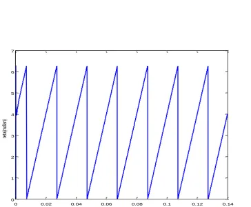
0 0.02 0.04 0.06 0.08 0.1 0.12 0.14
0 1 2 3 4 5 6 7
time(s)
te
ta
(ra
di
an
)
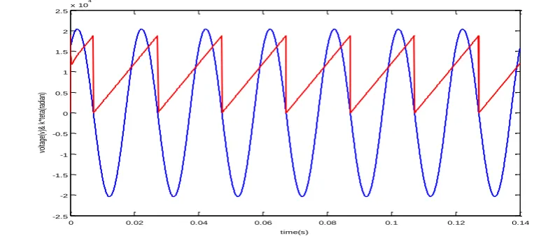
0 0.02 0.04 0.06 0.08 0.1 0.12 0.14 -2.5
-2 -1.5 -1 -0.5 0 0.5 1 1.5 2 2.5
x 10 4
time(s)
vo
lta
ge
(v
)&
k
*te
ta
(ra
dia
n)
Fig 5. Balanced three-phase detected phase angle along with voltage wave form of phase a.
V. CONCLUSION
This paper has developed a framework for constructing phase-locked loops that perform phase and frequency tracking directly on compressive measurements. It is expected to provide an easy selection guidance of an appropriate PLL for specific applications. In this paper, we proposed a PLL architecture which eliminates the use of passive analog loop filters and therefore, avoids their disadvantages.
REFERENCES
[1] E. Barklund, N. Pogaku, M. Prodanovic, C. Hern, and T. C. Green, 2010, ―Energy management in autonomous microgrid using stability-constrained droop control of inverters,‖ IEEE Trans. Power Electron., vol. 23, no. 5, pp. 2346–2352.
[2] G. Josep, C. Vasquez Juan, M. José, G. de V. Luis, and C. Miguel, 2012, ―Hierarchical Control of
Droop-Controlled AC and DC Microgrids—A General Approach Toward Standardization,‖ IEEE Trans.
Power Electron., vol. 58, no. 1, pp. 158.172.
[3] J. C. Vasquez, J. M. Guerrero, A. Luna, P. Rodriguez, and R. Teodorescu, 2009, ―Adaptive droop control applied to voltage-source inverters operating in grid-connected and islanded modes,‖ IEEE Trans. Ind. Electron., , vol. 56, no. 10, pp. 4088–4096.
[4] J. Kim, Josep M. Guerrero, R. Pedro, and T. Remus, 2011, ―Mode Adaptive Droop Control With Virtual Output Impedances for an Inverter-Based Flexible AC Microgrid,‖ IEEE Trans. Power Electron., vol. 26, no. 3, pp. 689-701.
[5] Balaguer, I.J. Qin Lei Shuitao Yang Supatti, U. Fang Zheng Peng, 2010, ―Control for Grid-Connected and Intentional Islanding Operations of Distributed Power Generation,‖ Industrial Electronics, IEEE Transactions., vol. 58, no. 4, pp. 1259-1267.
[6] Klapp, D. Vollkommer, H.T, 2007, ―Application of an Intelligent Static Switch to the Point of Common Coupling to Satisfy IEEE 1547 Compliance,‖ Power Engineering Society General Meeting, IEEE. [7] M. Guerrero Josep, C. Vásquez Juan, M. José, C. Miguel, and G. de V. Luis,2009, ―Control Strategy for
Flexible Microgrid Based on Parallel Line-Interactive UPS Systems,‖ IEEE Trans. Ind. Electron., vol. 56, no. 3, pp. 726-736.