Static Analysis of Rolling Bearing Using Finite Element
Analysis
Mr. SIDDOJU SATHEESH, PG Scholar
Mr.V.V.K.MOHAN KUMAR, M.Tech, Assistant Professor
Dr. AMITKUMAR HALDAR, Ph.D, Professor
Department of Mechanical Engineering
Asoka institute of engineering & Technology, YADADRI (dist).
ABSTRACT:
In this study the static analysis of an angular contact ball bearing using Finite Element Method is investigated. The main goal is to find the most
important influencing parameters for radial
stiffness of the bearing under an axial load. All the results are based on one specific angular contact ball bearing with the radius of ball around 22 mm and the inner and outer groove radii around 11mm.
The factors which mostly influence the radial reaction force from the housing to the outer ring are analyzed. The most important parameter which affects the reaction force is the curvature of the ball and the raceway of inner and outer ring. An increase of the ball diameter by 1.3% leads to the increase of reaction force by 27%. A decrease of ball diameter by 1.3% results in the decrease of reaction force by 9.3%.
With respect to the Finite Element formulation, the next important parameters are the mesh density and normal contact stiffness factor FKN if Augmented Lagrange is used. The mesh density affects the contact stiffness and the whole reaction force mostly in contact region. After the program finds a suitable contact area the mesh density affects the reaction force only a little. For example if the number of nodes increases by approx.
6 times, the final reaction force increases only 13.8%. For the penetration further investigation shows that the reaction force has little sensitivity to it. For example, when the penetration increases from 0 (Pure Lagrange method) to 0.0056 mm (Pure Penalty method) which is relative large in bearing analysis, the final reaction force decreases by only 1%.
The second goal of this study is to simplify this angular contact ball bearing using beam element between the inner and outer ring to reduce the number of nodes and shorten the calculation time.
For this specific ball bearing, it is possible to use a “beam star" structure with 12 beams and the radius of each circular beam is 4.5mm. Although it has an equivalent stiffness as the bearing with ball, for some other kind of bearing and the angular contact ball bearing with different geometry size, further investigation should be carried out.
I.INTRODUCTION
TO
ROLLING
BEARINGS
The term “rolling bearing” includes all forms of roller and ball bearing which permit rotary motion of
a shaft * [1]
Normally a whole unit of bearing is sold in the market, which includes inner ring, outer ring, rolling element (balls or rollers) and the cage which separates the rolling element from each other.
Rolling bearings are high precision, low cost but commonly used in all kinds of rotary machine. It takes long time for the human being to develop the bearing from the initial idea to the modern rolling bearing which can be seen from Fig.1-1.
FIG.1.
history of bearing
conveniently when it‟s broken. In the mechanical system shown in Fig.1-1-1, it is also possible to amount the shaft directly with housing. However, when this mechanism has some problem, the only possibility to recover the function of this system is to replace the housing or the shaft. From the mechanical engineer point of view, both of them are not only very expensive but also time consuming to manufacture a new housing or shaft with the same parameters.
However when the bearings are used between them, the situation will be different. Normally there is no relative motion between shaft and inner ring or the outer ring with housing. So it has less possibility for the shaft or housing to be worn out. Usually the bearing first cracks and then the shaft or housing is broken. If the above situation happens it is really easy to figure it out: just buy a new bearing from the market with the same parameter and replace it. That‟s why bearings are so often used.
FIG.2. MECHANICAL SYSTEM
2. FACTORS INFLUENCING THE REACTION FORCE
INTRODUCTION
Since one is interested to see how the structures
response under external load, then it is
necessary to investigate the relation between the
reaction force and the displacement. It is also of
great necessity to figure out which factors will
influence the reaction force. The influencing
factors can be classified into 2 groups:
physical and numerical part. Physical part
includes the geometry, friction coefficient and
the boundary conditions. Numerical parameters
are mesh density and penetration. In the
following part, the relation between the reaction
force and these parameters will be analyzed.
2.1 NUMERICAL INFLUENCING FACTORS TO THE REACTION FORCE
Concerning the numerical aspects using FEM, the influencing factors may be the mesh density of the finite element model, the penetration caused by the numerical approximation.
MESH DENSITY AND REACTION FORCE The pictures shown in Fig.3-1 are different meshes of angular contact ball bearing model. Mesh_(a) exhibits us one coarse mesh because there are only several elements in the y-direction. The elements in the x-direction are large as well. Mesh_b is fine but not reasonable because the elements are not so regular and they are distorted. By means of “mesh sizing” the element size or the number of division of edges can be modified so that finer and more reasonable mesh can be attained.
FIG.3. different mesh density
housing. The reaction force in y direction for all the meshes are shown in Fig.2-17.
Fig.3 reaction force comparison
Chart 3-1 statistic data for different meshes
Chart 3-2 reaction force data
Fig.3-3 difference vs displacement
Combining chart 3-1 and 3-2, one can see that the number of nodes increases by approx. 6 times, the final reaction force increases only 13.8%.As shown in the Fig.3-2, the most nonlinear region for the reaction force is between the
III .CONTACT ANALYSIS
3.1 Contact Area Type
According to the contact area shape (under no external load), there are point contact and line contact. It is obvious that after load applied line contact will become rectangle contact and point contact will be an ellipse contact area. Fig. 4-1 shows us the contact area type. For the bearing, initially the point contact happens between the ball and raceways
under no external load. After the load—
displacement or force is applied, the point will become an area contact.
In the numerical formulation, there are two groups of contact: point-surface contact and Surface-surface contact.
Fig. 4 contact area type [1]
In ANSYS, the contact is generated by pair. For the point-surface contact, the `point` is contact and the `surface` is target. For surface-surface contact, both contact and target are surfaces and they have to be specified which surface is contact and which is target. No matter it‟s point-surface contact or surface-surface contact, as soon as they are identified, they are then one pair. One can not exist without the other.
In the following part of this chapter, all the discussions are based on the surface-surface contact.
Augmented Lagrange Method
have their own advantages and disadvantages. Now a new algorithm which combines both namely Augmented Lagrange will be presented.
The „contact term‟ in equation (4-2) reads as following:
N , T are the contact stiffness in normal and
tangential direction
Augmented Lagrange augments the Lagrange part by penalty terms. When the program is processed with Augmented Lagrange, the program first uses penalty method to find the equilibrium point and then use Lagrange part to minimize the penetration. The user can also specify the penetration tolerance for the final solution. ( One thing to mention is that after each equilibrium point the solver eliminates penetration 3 times but no matter how much it will be at the end).Also the system doesn‟t blow up and all the solvers can be used. However, it needs more calculation time and ill-conditioned matrices may result in large contact stiffness.
IV. SIMULATION OF ANGULAR
CONTACT BALL BEARING WITH
SIMPLIFIED MODEL USING BEAM ELEMENT
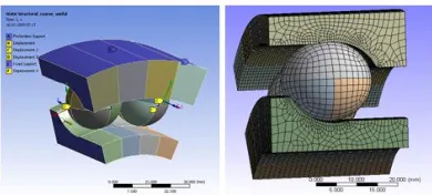
The Whole Model of Angular Contact Ball Bearing
Fig. 5-1 shows the model of inner ring and outer ring which can be done in ANSYS Workbench simply suppressing all the balls. The simplified model will also use this geometry to do the calculation, so the influence from the geometry of inner ring and outer ring is the same as that to the exact model. All the effort will be put on the influences of beams to the structure in order to finally make the difference between the solution with ball and beam as small as possible.
Fig.4.1 inner and outer ring for the simplified model
It has been explained in chapter 1 that a part of the whole model can be used for the calculation, which is shown in Fig. 5-2.
To make the model in Fig.5-2 converge is not so easy because of the initial geometrical gab between balls and inner ring and outer ring and the rotation of the two balls, which makes the program not so easy to find the contact points and also the rotation of the two balls. The trick to these is to apply some constraints on both balls to prevent the translation in Z direction shown in Fig. 5-2. In order to solve the initial gab, at first step, it is possible to solve only the contact gab and then from second step on load will be applied. This is a very convenience way to solve convergence problem because of initial gab or penetration.
Fig. 4-2 part model for the calculation and mesh
As the solid element does not affect the reaction force too much, one can see that in Fig.5-2, the element for the inner and outer ring is relatively large compared to the elements in contact region. The material model and parameter is the same to that in chapter 2.3.1
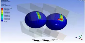
Result of Target Model
Fig.4-3 reaction force of the model with 2 balls
Fig.5.contact status
The force reaction is plotted in Fig.5-3 and contact status and penetration are shown in Fig.5-4 and 5-5 respectively.
Fig. 6. contact penetration
This penetration is small enough and this reaction force plot will be used as the target plot and finally the solution of simplified model with beam between the inner and outer ring will be compared with this plot.
Possible Ways to Simplify Angular Contact Ball
Bearing *5a
Now the simplified model with beam is going to be created.
Applied Displacement to the Model
Fig. load diagram
Fig.7. contact
Fig . 9. minimum principle stress of the outer surface of inner ring
V. CONCLUSION
The final conclusion for this chapter may be drawn: it is possible to use beam to simplify the roller bearing. But for the angular contact ball bearing, the ball is possible to be replaced by beam if and only if the interest is to compare or investigate the final reaction force. For this bearing, 12 beams in one beam star and radius of each beam 4.5 mm can have a similar stiffness of one ball.
However, if one is interested in investigating the contact issue inside the bearing, for example, contact penetration or contact pressure, then it is not a good idea to use beam to represent the ball between the inner and outer ring. Perhaps it is very necessary to use the ball itself to compare the simulation results with the experiment data.
VI. SUMMARY AND PROSPECTS
In this study the static analysis of rolling bearing especially one specific angular contact ball bearing using FEM has been performed.
Important physical and numerical affecting factors of the mechanical system of rolling bearing have been analyzed. Two modeling ways were constructed: full FE model with ball and FE simplified model where balls are replaced by a kind of specific beam structure “beam star”. The factors like curvature of ball and raceways, the boundary condition, mesh density and penetration are investigated. The most important parameter which affects the reaction force is the geometrical curvature of the ball and the raceway of inner and outer ring. A very small change of the ball diameter (increased by 1.3%) can lead to large variation of the final reaction force (increased by 27%). One can find relevant investigation in Chapter 2. So if the FE model of angular contact ball bearing is constructed, the radii of ball and raceways should be as accurate as possible.
If the numerical aspects are considered, mesh density and normal contact stiffness factor FKN (if Augmented Lagrange is used) are the two important parameters. The contact stiffness and the reaction force are sensitive to the mesh density mainly in the region where the structure behaves most nonlinearly. In other words, beyond that region, the mesh density affects the reaction force only a little. For instance when the number of nodes increases by approx. 6 times, the final reaction force increases only13.8%. It is suggested that for the single element size it should be less than approx.2% of ball diameter (here ball diameter is approx.22mm).
For the penetration further investigation shows that the radial reaction force is not so sensitive to it. For example, when the penetration increases from 0 (Pure Lagrange method) to 0.0056 mm (Pure Penalty method), the final reaction force decreases only approx.1%, but in the most nonlinear behavior region, the reaction force decreases maximally 8.5%. It is advised that under the conditions of good convergence behavior and not so long computation time, the customer can choose the FKN as large as possible (if Augmented Lagrange or Pure Penalty method is used). One can find this information in Chapter 2.
With respect to the simplification of rolling bearing with beam elements, it is possible to use beams between the inner and outer ring to simplify the roller bearing.
Through the investigation of the beam star, one finds that the stiffness of the structure is sensitive to the number of beam and the radius of beam. For this specific angular contact ball bearing, twelve beams in one beam star can have a similar stiffness to the ball. However, for the contact part, the beam star can not simulate the real situation of contact inside the angular contact ball at all. So for the angular contact ball bearing, it is not an ideal plan to replace the ball by beam elements.
All the mentioned results are based on the specific angular contact ball bearing with a ball diameter around 22mm and the inner and outer raceways diameter around 11mm. For other geometrical sizes of this kind of angular contact ball bearing, the number of beams or the radius of the beam in one beam star is still unknown and further investigation must be carried out.
For the static analysis this FE model of angular contact ball bearing is from the literature and the static real bearing testing results about it is still missing. As soon as one gets relevant experimental data, it is possible to verify these numerical results further.
For the future study it is also very important to simulate the dynamic behavior of rolling bearing using FEM. Generally many rolling bearings are used in high speed machines. For the high speed machinery, the vibration and noise are two challenging problems which are normally from the bearing. Hence in the future it is of great importance to investigate the dynamic behavior of rolling bearing so that one can predict the system vibration responses and minimize the noise level.
BIBLIOGRAPHY
[1]Tedric A. Harris; Rolling Baring Analysis, John Wiley& Sons, Inc.1967
[2] Tedric A. Harris; Rolling Baring Analysis, John Wiley& Sons, Inc., fourth edition,2001
[3]Vince Adams and Abraham Askenazi; Bilding Btter Poducts with Finite Element
Analysis; on world press,1998
[4]T.Stolarski Y.Nakasone. S.Yoshimoto;
Engineering analysis with ANSYS software; Elsevier Butterworth-Heinemann, Oxford, 2006
[5]http://www.kmlbearing.cn/common/catalog_data /01/0101/010101/01010101/image
_01010101_b.gif
[6] Release 11.0 Documentation for ANSYS
[7]Dr.-Ing.GünterMüller/Dipl.-Ing.Clemens Groth; FEM für Praktiker, 4.aktualisierte
Auflage 1999; expert-Verlag
[8] http://www.promshop.info/cataloguespdf/a005-011.pdf
[9]http://www.skf.com/skf/productcatalogue/jsp/vi ewers/productTableViewer.jsp?&la
ng=de&tableName=1_3_1&presentationType=3& startnum=14
[10]Lothar Issler Hans Ruoß Peter
Häfele; Festigkeitslehre Grundlagen 2.Auflage; Springer
[11] Nadellager Zylinderrollenlager Katalog 307; INA Wälzlager Schaeffler
![Fig. 4 contact area type[1]](https://thumb-us.123doks.com/thumbv2/123dok_us/7744019.1268719/3.612.344.514.301.445/fig-contact-area-type.webp)