An Extended Wavenumber-Domain Algorithm Combined with
Two-Step Motion Compensation for Bistatic Forward-Looking SAR
Yuebo Zha1, * and Wei Pu2
Abstract—With appropriate geometry configurations, bistatic Synthetic Aperture Radar (SAR) can break through the limitations of monostatic SAR on forward-looking imaging. Thanks to such a capability, bistatic forward-looking SAR (BFSAR) has extensive potential applications. For the focusing problem of BFSAR, wavenumber-domain algorithm is accepted as the ideal solution. However, in practical application, the processing is limited because of its inability to combine the range-dependent motion compensation (MoCo). To cope with such a problem, an extended wavenumber-domain algorithm for BFSAR is derived in this paper. By modifying the reference function and mapping relationship in frequency interpolation, the extended wavenumber-domain algorithm of BFSAR integrates a two-step motion compensation. Simulation results verify the effectiveness of the proposed method.
1. INTRODUCTION
In bistatic synthetic aperture radar (SAR), as the transmitter and receiver are mounted on separate platforms, it is possible to achieve high-resolution image in the forward-looking area. Hence, bistatic forward-looking SAR (BFSAR) has significant application value in the field of airplane navigation, landing, etc.
Some theories for BFSAR have been developed in [1], and some reconstruction methods, such as range-Doppler [3] and Chirp-Scaling [4–6], are ongoing. In contrast, wavenumber-domain algorithm [7] is viewed as an ideal solution to the BFSAR focusing problem as it solves the severe spatial dependence. Nevertheless, the wavenumber-domain algorithm cannot satisfy the requirement of practical application as it has no possibility of including a high precision, range-dependent motion compensation (MoCo). Compared with the range-Doppler (RD) and chirp scaling (CS) algorithms with two-step MoCo, only the first order MoCo can be applied in the wavenumber-domain algorithm. The first order MoCo is the range-independent part of MoCo and is applied directly before or after range compression. In the case of high-resolution systems, a precise compensation of the range-dependent components of the motion error is essential. This processing step, which has to be implemented after range cell migration correction (RCMC) and before azimuth compression, is not possible.
Reigber et al. propose an extended wavenumber-domain algorithm for monostatic SAR [8]. By changing the reference function multiplication and mapping relationship in frequency interpolation, the algorithm can cope with range-dependent motion errors. However, it cannot be directly applied in bistatic forward-looking mode as the different spectrum expression between monosatic SAR and bistatic SAR [9, 12].
Received 13 July 2016, Accepted 11 October 2016, Scheduled 31 October 2016
* Corresponding author: Yuebo Zha ([email protected]).
1 China Electronics Technology Group Corporation No. 38 Research Institute, 199 Xiangzhang Avenue, Hi-Tech Zone, Hefei, Anhui
In the following, an extended wavenumber-domain algorithm with integrated two-step MoCo for BFSAR is proposed in this paper, which is also an extension of the previous result [2]. The rest of this paper is organized as follows: An wavenumber-domain algorithm for BFSAR based on the point target reference spectrum (PTRS) calculated by MSR is presented in Section 2. The extended wavenumber-domain algorithm is analytically derived in Section 3. Azimuth compression is implemented independently, so that range-dependent MoCo can be integrated. Simulation results are carried out to verify the effectiveness of the proposed method in Section 4. Finally, we draw our conclusions in Section 5.
2. WAVENUMBER-DOMAIN ALGORITHM FOR BFSAR
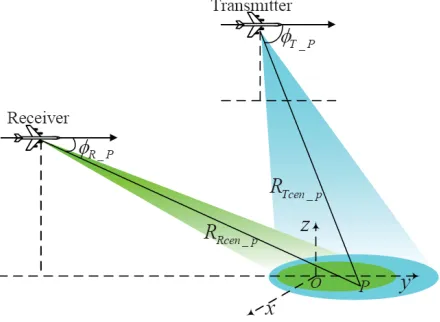
In this section, the signal model of BFSAR is formulated, and the corresponding geometry is shown in Fig. 1. Transmitter and receiver are assumed to move along two lines parallel to y axis with equal velocity V. The coordinate origin O(xref, yref,0) is set to be the reference target and P(x, y,0) is an arbitrary point target in the imaging area. The squint angles θT P, θR P and initial ranges RT cen P,
RRcen P shown in Fig. 1 are measured at the composite beam center crossing time of target P.
Figure 1. Imaging geometry configuration of BFSAR.
Assume that Linear Frequency Modulated (LFM) pulses are transmitted by the radar and the echo data from targetP can be adequately described by
s(τ, η) =rect
τ −2rP(η)/c
Tr
×rect( η
Ta)×exp
−jπKr
τ −2rP(η)
c
2
×exp
−j2π2rP(η)
λ
(1)
where τ denotes the range time, and the azimuth time η is chosen to be zero at the composite beam center crossing time of the scene center. λis the wave-length, Kr is the transmitted chirp rate,cis the speed of propagation,Tr is the timewidth of the LFM pulse and Ta is the synthetic aperture time.
In Eq. (1),rP(η) represents the instantaneous two-way range of the targetP.
rP(η) =rP T(η) +rP R(η) (2)
where
rP T(η) =
R2
T cen P + (V η−y)2−2RT cen P(V η−y) cosθT P (3)
rP R(η) =
R2
Rcen P + (V η−y)2−2RRcen P(V η−y) cosθR P (4)
be deduced. Using the stationary phase point, analytical expression of PTRS of BFSAR with respect to targetP is calculated.
S(fτ, fη) =Wr(fτ)Waz(fη) exp{jφP(fτ, fη)}
=Wr(fτ)Waz(fη) exp
−j2πRcen P
c Fref(fη, fτ)−j2πfη y
v −
jπf2
τ
Kr
(5)
In Eq. (5),φP(fτ, fη) is the phase of PTRS, andFref(fη, fτ) is the frequency term.
Fref(fη, fτ) = − c
2
4αref(fc+fτ) · fη+ (fc+fτ)
kref1
c
2
− c3βref
8α3
ref(fc+fτ)2
· fη+ (fc+fτ)kref1
c
3
−c
4(9β2
ref/α5ref −4γref/α4ref)
64(fc+fτ)3 × fη+ (fc+fτ)
kref1
c
4
+ (fc+fτ) (6)
Rcen P is the two-way range of target P measured at the composite beam center crossing time; fc corresponds to the center frequency;fη and fτ denote the azimuth and range frequencies, respectively.
Wr(·) represents the spectral shape of the transmitted pulse, andWaz(η) denotes the shape of Doppler
spectrum. αref, βref and γref are the rewritten results of kref2, kref3 and kref4 by performing some algebraic manipulations, wherekref1,kref2,kref3 andkref4 represent the first, second, third and fourth order derivatives of the instantaneous two-way range history of the reference target atη= 0, respectively (seen in [11]).
Based on the PTRS in Eq. (5), an wavenumber-domain algorithm can be derived. Firstly, a reference function multiplication (RFM) is performed to accomplish the 2-dimensional bulk focus.
SRF M (fτ, fη) = exp
j2πRcen refc Fref(fη, fτ) +jπf
2
τ
Kr +j2πfη
yref
v
(7)
Then, a Stolt interpolation operation can be utilized to handle the range-dependent part of RCM, azimuth compression, and second range compression (SRC) correctly.
f
τ +fc =Fref(fη, fτ) (8) Nevertheless, as RCMC and azimuth compression are performed simultaneously, it cannot integrate the range-dependent MoCo.
3. EXTENDED WAVENUMBER-DOMAIN FOR BISTATIC FORWARD-LOOKING SAR
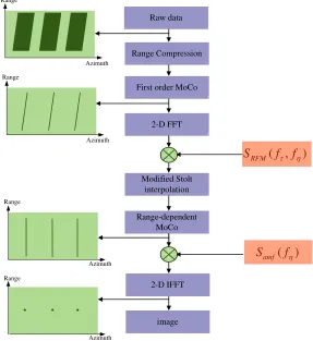
Associated with PTRS in Section 2, an extended wavenumber-domain algorithm for BFSAR is proposed in this section. The proposed algorithm uses modified RFM and modified Stolt interpolation in order to separate azimuth compression. Therefore, range-dependent MoCo can be applied before azimuth compression. The detail of the proposed method is presented.
3.1. Modified RFM
Firstly, range compression is performed, and the first order MoCo is accomplished. Then, the data after first order MoCo is transformed into 2-D frequency domain.
In Eq. (7), the RFM focuses the reference target completely. An alternative way is to transform the frequency factor in Eq. (7) into a different Fourier integral, which separates the RCM correction and SRC from the actual azimuth compression. The frequency term in Eq. (6) is expanded into the series of range frequencyf.
Fref(fτ, fη)≈Faz(fη) +Frcm(fη)fτ+Fscr(fη)fτ2 (9)
whereFaz(fη) denotes the azimuth compression term,
Frcm(fη) denotes the range cell migration (RCM) factor,
Frcm(fη, fτ) =Fref (fη, fτ)|fτ=0 (11)
and Fsrc(fη, fτ) is the second range compression part.
Fsrc(fη, fτ) = 12Fref(fη, fτ)|fτ=0 (12)
In order to separate azimuth compression, Faz(fη) is subtracted from the reference function, and Eq. (7) is changed into
SRF M(fτ, fη) = exp
j2πRcen refc [Frcm(fη) +Fsrc(fη)] +j2πfηyref
v
(13)
whereRcen ref is two-way range of the reference target measured at the composite beam center crossing time.
Here, only bulk RCM and bulk SRC are accomplished in RFM, while bulk azimuth compression is separated. Residual phase of PTRS in Eq. (5) converts into
φP1(fτ, fη) =−j2πRcen ref
c Faz(fη)−j2πfη
y−yref
v −j
2πΔRP cen
c Fref(fη, fτ). (14)
where ΔRP cen represents the range coordinate of target P.
ΔRcen P =Rcen P −Rcen ref (15)
3.2. Modified Stolt Interpolation and Azimuth Compression
In order to separate azimuth compression, a change of variables, different from the Stolt mapping in Eq. (8), is applied.
fτ new +fc =Frcm(fη)fτ +Fsrc(fη)fτ2 (16) The modified Stolt mapping additionally introduces a frequency shift and performs residual RCMC and residual SCR.Faz(fη) denotes residual azimuth compression in Stolt interpolation. Hence, residual azimuth compression is eliminated in Eq. (16). The residual phase of PTRS after modified Stolt interpolation changes into
φP2(fτ, fη) =−j
2πΔRP cen
c
fτ new+fc−2πfηy−vyref −j2πΔRcP cenF1ref(fη)
−j2πRcen refc F1ref(fη) (17)
At this point, the range-dependent motion compensation can be applied because RCM correction has been done completely, while azimuth compression has not been implemented yet.
Here, phase correction of the form
Samf(fη) = exp
j2πRP cen
c Faz(fη)
(18)
performs the final azimuth focusing. After multiplied by the azimuth compression phase, the residual phase of PTRS is
φP3(fτ new , fη) =j2πΔRP cen
c
fc+fτ new −j2πfηy−yref
v (19)
Azimuth Range
Azimuth Range
Azimuth Range
Azimuth Range
( , )
RFM S fτ fη
( )
amf S fη First order MoCo
Range Compression Raw data
2-D FFT
Range-dependent MoCo
2-D IFFT Modified Stolt
interpolation
image
Figure 2. Flowchart of the extended wavenumber-domain algorithm for BFSAR.
Table 1. Simulation parameters.
Parameter Value
Carrier frequency 9.6 GHz
Band width 400 MHz
Synthetic aperture time 5 s
Nominal Radar platform velocity 200 m/s Pulse repetition frequency 1000 Hz Coordinates of transmitter (6,−3,6) km Coordinates of receiver (0,−6,4) km
4. SIMULATION RESULTS
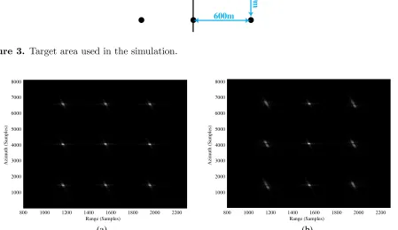
To evaluate the performance of the proposed extended wavenumber-domain algorithm, simulations for BFSAR are carried out in this section. The simulation parameters are shown in Table 1. 9 targets are set in the scene area as shown in Fig. 3. The distance between two adjacent targets along azimuth direction is 600 m while the adjacent distance along range axis is 400 m.
To better evaluate the performances of the proposed method, the raw data are added by the white Gauss noise withSNR= 5 dB. Motion errors are added to the raw data of BFSAR. Let ΔxT and ΔxR denote the deviations inx direction for the transmitter and receiver, respectively, while ΔzT and ΔzR denote the height deviations of the transmitter and receiver, respectively. Functions of these deviations with respect to the azimuth time tare
ΔxT = 2 cos(2π0.8t), ΔxR= 2 cos(2π0.8t)
Azimuth Range
600m
400m
Figure 3. Target area used in the simulation.
Range (Samples)
Azimuth (Samples)
800 1000 1200 1400 1600 1800 2000 2200 1000
2000 3000 4000 5000 6000 7000 8000
Range (Samples)
Azimuth (Samples)
800 1000 1200 1400 1600 1800 2000 2200 1000
2000 3000 4000 5000 6000 7000 8000
(a) (b)
Figure 4. (a) Wavenumber-domain without range-dependent MoCo. (b) Extended wavenumber-domain with two-step MoCo.
Figure 4(a) indicates the imaging result using the Omega-K algorithm in [11] with first order MoCo. In the presence of range dependant motion errors, the targets with the reference range sum are well focused, while the focus quality of the targets apart from the swath center deteriorates seriously. Fig. 4(b) shows the imaging result by the proposed extended wavenumber-domain algorithm with two-step MoCo. With both range independent and dependent MoCo, all the targets are focused well.
To quantify the precision of the proposed algorithm, targets O, A and B are analyzed in more detail. Target O is assumed to be located in the scene center, and the coordinates of target A and
B are (−400,−600,0) m and (0,600,0) m, respectively. In order to highlight the performance of this approach further, points A,O, and B are analyzed in more detail. Fig. 5 shows the contours of point
A,O, andB processed by the extended wavenumber-domain with two-step MoCo. To show the details, the results are interpolated eight times. Fig. 6 gives the contours of points A,O, and B processed by the wavenumber-domain without range-dependent MoCo. As can be seen from Fig. 5 and Fig. 6, only the targets in the reference azimuth bin can be focused well by the two-step MoCo. The targets at the corners of the scenario are partially unfocused. However, we can find that the proposed method can focus these targets simultaneously. The imaging results display good shape of a 2-D sinc function which is the point spread function of a SAR system.
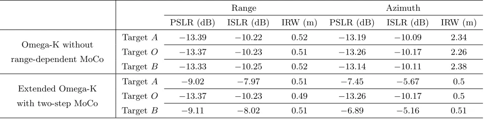
three targets focused by the proposed extended wavenumber-domain algorithm, the PSLR and ISLR both agree well with the theoretical values of −13.27 dB and −10.24 dB, respectively. Moreover, in Table 2, for the image results focused by the wavenumber-domain algorithm without range-dependent MoCo, targetsAandBare defocused by the range-dependent motion errors. The quality measurements valid the effectiveness of the proposed algorithm further. The Omega-K algorithm in Table 2 means the imaging algorithm in [11].
50 100 150 200 250 300
100 200 300 400 500 600
(a)
50 100 150 200 250 300
100 200 300 400 500 600
(b)
50 100 150 200 250 300
100 200 300 400 500 600
(c)
Figure 5. Extended wavenumber-domain with two-step MoCo. (a) TargetA. (b) TargetO. (c) Target
B.
50 100 150 200 250 300
100 200 300 400 500 600
(a)
50 100 150 200 250 300
100 200 300 400 500 600
(b)
50 100 150 200 250 300
100 200 300 400 500 600
(c)
Figure 6. Wavenumber-domain without range-dependent MoCo. (a) Target A. (b) Target O. (c) TargetB.
Table 2. Imaging quality parameters.
Range Azimuth
PSLR (dB) ISLR (dB) IRW (m) PSLR (dB) ISLR (dB) IRW (m)
Omega-K without
range-dependent MoCo
TargetA −13.39 −10.22 0.52 −13.19 −10.09 2.34
TargetO −13.37 −10.23 0.51 −13.26 −10.17 2.26
Target B −13.33 −10.25 0.52 −13.14 −10.11 2.38
Extended Omega-K
with two-step MoCo
TargetA −9.02 −7.97 0.51 −7.45 −5.67 0.5
TargetO −13.37 −10.23 0.49 −13.26 −10.17 0.5
5. CONCLUSION
An extension of wavenumber-domain scheme of BFSAR has been proposed in this paper, which directly integrates a two-step MoCo. This algorithm resolves the issue of inability of the conventional wavenumber-domain approach to perform a range-dependant MoCo, which is necessary when processing airborne BFSAR data. This method has the advantages of being able to integrate two-step MoCo as well as maintaining focusing precision. Performance of the proposed algorithm has been demonstrated by the simulations.
REFERENCES
1. Wu, J., J. Yang, Y. Huang, H. Yang, and H. Wang, “Bistatic forward-looking SAR: Theory and challenges,” 2009 IEEE Radar Conference, 1–4, IEEE, 2009.
2. Pu, P., J. Yang, Y. Huang, H. Yang, and W. Li, “A residual range cell migration correction algorithm for SAR based on low-frequency fitting,” 2015 IEEE Radar Conference, 1300–1304, IEEE, 2015.
3. Qiu, X., D. Hu, and C. Ding, “Some reflections on bistatic SAR of forward-looking configuration,”
IEEE Geoscience and Remote Sensing Letters, Vol. 5, No. 4, 735–739, 2008.
4. Wu, J., J. Yang, Y. Huang, and H. Yang, “Focusing bistatic forward-looking SAR using chirp scaling algorithm,” 2011 IEEE Radar Conference (RADAR), 1036–1039, IEEE, 2011.
5. Li, Z., J. Wu, W. Li, Y. Huang, and J. Yang, “One-stationary bistatic side-looking sar imaging algorithm based on extended keystone transforms and nonlinear chirp scaling,” IEEE Geoscience and Remote Sensing Letters, Vol. 10, No. 2, 211–215, 2013.
6. Wu, J., Z. Li, Y. Huang, J. Yang, H. Yang, and Q. H. Liu, “Focusing bistatic forward-looking SAR with stationary transmitter based on keystone transform and nonlinear chirp scaling,” IEEE Geoscience and Remote Sensing Letters, Vol. 11, No. 1, 148–152, Jan. 2014.
7. Shin, H.-S. and J.-T. Lim, “Omega-k algorithm for airborne forward-looking bistatic spotlight SAR imaging,”IEEE Geoscience and Remote Sensing Letters, Vol. 6, No. 2, 312–316, 2009.
8. Reigber, A., E. Alivizatos, A. Potsis, and A. Moreira, “Extended wavenumber-domain synthetic aperture radar focusing with integrated motion compensation,” IEE Proceedings — Radar, Sonar and Navigation, Vol. 153, No. 3, 301–310, Jun. 2006.
9. Loffeld, O., H. Nies, V. Peters, and S. Knedlik, “Models and useful relations for bistatic SAR processing,” GIEEE Transactions on eoscience and Remote Sensing, Vol. 42, No. 10, 2031–2038, Oct. 2004.
10. Neo, Y. L., F. Wong, and I. G. Cumming, “A two-dimensional spectrum for bistatic SAR processing using series reversion,” IEEE Geoscience and Remote Sensing Letters, Vol. 4, No. 1, 93–96, 2007. 11. Liu, H., T. Wang, Q. Wu, and Z. Bao, “Bistatic SAR data focusing using an Omega-k algorithm
based on method of series reversion,” IEEE Transactions on Geoscience and Remote Sensing, Vol. 47, No. 8, 2899–2912, 2009.