Migration from One CSP to Another using
Meta-Cloud
G. Satish
M.Tech (Computer Networks and Information Security) School of Information Technology, JNTUH
Hyderabad, India
Dr. G. Venkata Rami Reddy Computer Science and Engineering School of information Technology, JNTUH
Hyderabad, India
Abstract—In these recent years cloud computing paradigm has achieved widespread adoption. Its success is because of large customers’ ability to use services on demand with a pay-as-you go pricing model. Low costs and high flexibility make migrating to the cloud computing. Although having advantages, many companies hesitated to move to the cloud mainly because of conflicts related to the service facing the availability, data lock-in and legal consequences. Lock in is made as issue. But, even though public cloud availability is high, outages still occur as Businesses locked into such a cloud are essentially at a standstill. Moreover, these cloud providers generally don’t guarantee respective service level agreements (SLAs), so, businesses locked into a cloud where no guarantees that it will continue to provide the required quality of service (QoS). Finally, most public cloud providers’ terms of service let that provider may change pricing at any time. Hence, a business can be locks into a cloud has no mid- or long term control over its own IT costs.
At the level of all these problems, identify a need for businesses to monitor permanently the cloud they’re using migrate to a different cloud if they discover problems or if their estimates predict future issues.
Keywords— Cloud Computing, Meta-Cloud, Cloud Migration, Cloud Service Providers
I. INTRODUCTION
The Cloud Computing explains that the practice of using a network of remote servers hosted on the Internet to store, manage, and process data, rather than a local server or a personal computer.
The Cloud Service Provider (CSP) defines that a service provider that offers customers storage or software services available via a private (private cloud) or public network (cloud). Usually, it means the storage and software is available for access via the Internet.
The Cloud Migration defines that the process of transitioning all or part of a company’s or organizational data, applications and services from on-site premises behind the firewall to the cloud, where this information could be provided over the Internet on an on-demand basis. A cloud migration can present more challenges and raises security concerns, so cloud computing can also be enable a company to potentially reduce capital expenditures and operating costs while also benefiting from the dynamic scaling, the high availability, the multi-tenancy and the effective resource allocation advantages cloud-based computing offers.
The Meta Cloud explains that this would abstract away from existing offerings’ of particular Cloud Service Provider are technical incompatibilities, thus able to mitigate the vendor lock-in problems.
II. EXISTED SYSTEM
Before Cloud providers are flooding the market with extra confusing body of services, including maximum number of computer services such as the Amazon Elastic Compute Cloud (EC2) and VMware vCloud, such as the Amazon Simple Storage Service (S3). Some of these services are conceptually comparable to each other, but others are different, but they’re all, ultimately, incompatible and may not follow any standards but their own. So, further to complicate the situation, various companies not (only) build on public clouds for their cloud computing needs and combine the public offerings along with their own private cloud, called hybrid clouds
III. PROPOSED SYSTEM
Here, we introduce the concept of a Meta cloud that incorporates design time and runtime components. This Meta cloud would abstracts makes all away from existing offerings’ like technical incompatibilities, thus mitigating the vendor lock-in issues. It helps users to find the right set of cloud services for a particular use case and supports an application’s from initial deployment and runtime migration.
IV. PROCESS MODEL USED WITH JUSTIFICATION SDLC (Umbrella Model):
SDLC is nothing but Software Development Life Cycle. This is a standard which is used by every software industry to develop good softwares.
Stages in SDLC:
♦
Requirement Gathering♦
Analysis♦
Designing♦
Coding♦
Testing♦
MaintenanceRequirements Gathering Stage:
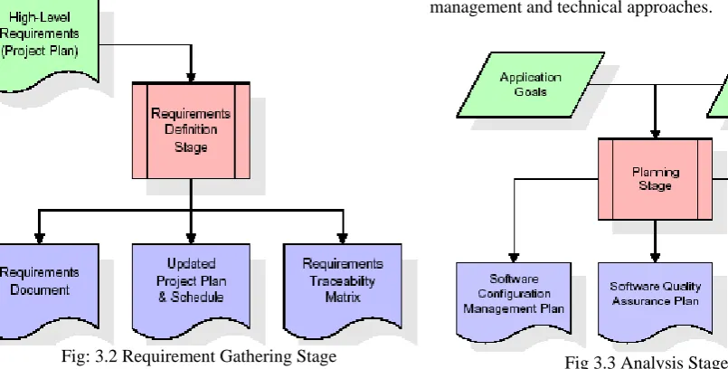
The requirements gathering process takes as its input the goals identified in the high-level requirements sections of the project planning. So, each goal will be polished into a set of one or more requirements. These requirements define the major functions of the intended application, define operational data areas and reference data areas, and define the initial data entities. Major functions include critical processes to be managed, as well as mission critical inputs, outputs and reports. A user class hierarchy is developed and associated with these major functions, data areas, and data entities. Each of these definitions is termed a Requirement. Requirements are identified by unique requirement identifiers and, at minimum, contain a requirement title and textual description.
Fig: 3.2 Requirement Gathering Stage
These requirements are fully described in the primary deliverables for this stage: the Requirements Document and the Requirements Traceability Matrix (RTM). The requirements document contains complete descriptions of each requirement, including diagrams and references to external documents as necessary. Note that detailed listings of database tables and fields are not included in the requirements document.
The title of each requirement is also placed into the first version of the RTM, along with the title of each goal from the project plan. The purpose of the RTM is to show that the product components developed during each stage of the software development lifecycle are formally connected to the components developed in prior stages.
In the requirements stage, the RTM consists of a list of high-level requirements, or goals, by title, with a
listing of associated requirements for each goal, listed by requirement title. In this hierarchical listing, the RTM shows that each requirement developed during this stage is formally linked to a specific product goal. In this format, each requirement can be traced to a specific product goal, hence the term requirements traceability.
The outputs of the requirements definition stage include the requirements document, the RTM, and an updated project plan.
♦
Feasibility study is all about identification of problems in a project.♦
No. of staff required to handle a project is represented as Team Formation, in this case only modules are individual tasks will be assigned to employees who are working for that project.♦
Project Specifications are all about representing of various possible inputs submitting to the server and corresponding outputs along with reports maintained by administrator.Analysis Stage:
The planning stage establishes a bird's eye view of the intended software product, and uses this to establish the basic project structure, evaluate feasibility and risks associated with the project, and describe appropriate management and technical approaches.
Fig 3.3 Analysis Stage
Designing Stage:
Fig: 3.4 Designing Stage
The design stage takes as its initial input the requirements identified in the approved requirements document. For each requirement, a set of one or more design elements will be produced as a result of interviews, workshops, and/or prototype efforts. Design elements describe the desired software features in detail, and generally include functional hierarchy diagrams, screen layout diagrams, tables of business rules, business process diagrams, pseudo code, and a complete entity-relationship diagram with a full data dictionary. These design elements are intended to describe the software in sufficient detail that skilled programmers may develop the software with minimal additional input.
When the design document is finalized and accepted, the RTM is updated to show that each design element is formally associated with a specific requirement. The outputs of the design stage are the design document, an updated RTM, and an updated project plan.
Development (Coding) Stage:
The development stage takes as its primary input the design elements described in the approved design document. For each design element, a set of one or more software artifacts will be produced. Software artifacts include but are not limited to menus, dialogs, and data management forms, data reporting formats, and specialized procedures and functions. Appropriate test cases will be developed for each set of functionally related software artifacts, and an online help system will be developed to guide users in their interactions with the software.
Fig: 3.5 Development Stage
The RTM will be updated to show that each developed artifact is linked to a specific design element, and that each developed artifact has one or more corresponding test case items. At this point, the RTM is in its final configuration. The outputs of the development stage include a fully functional set of software that satisfies the requirements and design elements previously documented, an online help system that describes the operation of the software, an implementation map that identifies the primary code entry points for all major system functions, a test plan that describes the test cases to be used to validate the correctness and completeness of the software, an updated RTM, and an updated project plan.
Integration & Test Stage:
During the integration and test stage, the software artifacts, online help, and test data are migrated from the development environment to a separate test environment. At this point, all test cases are run to verify the correctness and completeness of the software. Successful execution of the test suite confirms a robust and complete migration capability. During this stage, reference data is finalized for production use and production users are identified and linked to their appropriate roles. The final reference data (or links to reference data source files) and production user list are compiled into the Production Initiation Plan.
Fig: 3.6 Integration & Test Stage
The outputs of the integration and test stage include an integrated set of software, an online help system, an implementation map, a production initiation plan that describes reference data and production users, an acceptance plan which contains the final suite of test cases, and an updated project plan.
Installation & Acceptance Test:
After customer personnel have verified that the initial production data load is correct and the test suite has been executed with satisfactory results, the customer formally accepts the delivery of the software.
Fig: 3.7 Installation & Acceptance Stage
The primary outputs of the installation and acceptance stage include a production application, a completed acceptance test suite, and a memorandum of customer acceptance of the software. Finally, the PDR enters the last of the actual labor data into the project schedule and locks the project as a permanent project record. At this point the PDR "locks" the project by archiving all software items, the implementation map, the source code, and the documentation for future reference.
Maintenance:
Outer rectangle represents maintenance of a project, Maintenance team will start with requirement study, understanding of documentation later employees will be assigned work and they will undergo training on that particular assigned category.
For this life cycle there is no end, it will be continued so on like an umbrella (no ending point to umbrella sticks).
V. SOFTWARE REQUIREMENT SPECIFICATION
Overall Description
A Software Requirements Specification (SRS) – a requirements specification for a software system is a complete description of the behavior of a system to be developed. It includes a set of use cases that describe all the interactions the users will have with the software. In addition to use cases, the SRS also contains non-functional requirements. Nonnon-functional requirements are requirements which impose constraints on the design or implementation (such as performance engineering requirements, quality standards, or design constraints).
System requirements specification: A structured collection of information that embodies the requirements
of a system. A business analyst, sometimes titled system analyst, is responsible for analyzing the business needs of their clients and stakeholders to help identify business problems and propose solutions. Within the systems development lifecycle domain, the BA typically performs a liaison function between the business side of an enterprise and the information technology department or external service providers. Projects are subject to three sorts of requirements:
• Business requirements describe in business terms what must be delivered or accomplished to provide value.
• Product requirements describe properties of a system or product (which could be one of several ways to accomplish a set of business requirements.)
• Process requirements describe activities performed by the developing organization. For instance, process requirements could specify .Preliminary investigation examine project feasibility, the likelihood the system will be useful to the organization. The main objective of the feasibility study is to test the Technical, Operational and Economical feasibility for adding new modules and debugging old running system. All system is feasible if they are unlimited resources and infinite time. There are aspects in the feasibility study portion of the preliminary investigation
:
ECONOMIC FEASIBILITY
A system can be developed technically and that will be used if installed must still be a good investment for the organization. In the economic feasibility, the development cost in creating the system is evaluated against the ultimate benefit derived from the new systems. Financial benefits must equal or exceed the costs. The system is economically feasible. It does not require any addition hardware or software. Since the interface for this system is developed using the existing resources and technologies available at NIC, There is nominal expenditure and economic feasibility for certain.
OPERATIONAL FEASIBILITY
Proposed projects are beneficial only if they can be turned out into information system. That will meet the organization’s operating requirements. Operational feasibility aspects of the project are to be taken as an important part of the project implementation. This system is targeted to be in accordance with the above-mentioned issues. Beforehand, the management issues and user requirements have been taken into consideration. So there is no question of resistance from the users that can undermine the possible application benefits. The well-planned design would ensure the optimal utilization of the computer resources and would help in the improvement of performance status.
TECHNICAL FEASIBILITY
purpose is to create, establish and maintain a workflow among various entities in order to facilitate all concerned users in their various capacities or roles. Permission to the users would be granted based on the roles specified. Therefore, it provides the technical guarantee of accuracy, reliability and security.
External Interface Requirements User Interface
The user interface of this system is a user friendly Java Graphical User Interface.
Hardware Interfaces
The interaction between the user and the console is achieved through Java capabilities.
Software Interfaces
The required software is JAVA1.6.
Operating Environment
Windows XP, Linux.
HARDWARE REQUIREMENTS:
Processor : Pentium III
Speed : 1.1GHz RAM : 512MB
Hard disk : 20GB.
Keyboard : Standard Windows Keyboard. Mouse : Two or Three button mouse
Monitor : SVGA
.
SOFTWARE REQUIREMENTS:
Operating System : Windows95/98/2000/XP
Application Server : Tomcat5.0/6.X Front End : HTML, Java, JSP Scripts : JavaScript. Server side Script : Java Server Pages. Database : My SQL
Database Connectivity : JDBC.
VI. DESIGN
UML diagrams
The Unified Modeling Language allows the software engineer to express an analysis model using the modeling notation that is governed by a set of syntactic semantic and pragmatic rules.
A UML system is represented using five different views that describe the system from distinctly different perspective. Each view is defined by a set of diagram, which is as follows.
• User Model View
i. This view represents the system from the user’s perspective.
ii. The analysis representation describes a usage scenario from the end-users perspective.
• Structural Model view
i. In this model the data and functionality are arrived from inside the system.
ii. This model view models the static structures.
• Behavioral Model View
It represents the dynamic of behavioral as parts of the system, depicting the interactions of collection between various structural elements described in the user model and structural model view.
• Implementation Model View
In this the structural and behavioral as parts of the system are represented as they are to be built.
• Environmental Model View
In this the structural and behavioral aspects of the environment in which the system is to be implemented are represented.
Class diagram:-
The class diagram is the main building block of object oriented modelling. It is used both for general conceptual modeling of the systematics of the application, and for detailed modelling translating the models into programming code. Class diagrams can also be used for data modeling. The classes in a class diagram represent both the main objects, interactions in the application and the classes to be programmed.
A class with three sections.
In the diagram, classes are represented with boxes which contain three parts:
• The upper part holds the name of the class
• The middle part contains the attributes of the class
• The bottom part gives the methods or operations the class can take or undertake
Bet String username String beton String amount bet() User String user String pwd login() Migrate String server String app String name migrate() Template String app String cpu String ram String software String server String db createTemplate() Provider String provider String ipaddress String port String cost addProvider() Register String uname String pass String contact String email String address register() Receive ServerSocket server Socket socket start() Admin String user String pwd login()
Fig: 4.1 Class diagram
Use case diagram:-
add provider
view log
migrate cloud
view provider
view template
logout admin
create template
Fig: 4.2 Use case diagram for Admin
Use case diagram for User:-
register
login
bet user
logout
Fig: 4.3 Use case diagram for User
Sequence Diagram:-
Sequence diagram for Admin:
Admin Login Template Provider ViewLog MigrateCloud ViewProvider ViewTemplate
enter usr and pwd
[!correct]invalid
enter correctly
logged successfully
add template
template created
add provider
provider created
view details
migrate
view list of providers
view list of templates
Fig: 4.4 Sequence diagram for Admin
A sequence diagram is a kind of interaction diagram that shows how processes operate with one another and in what order. It is a construct of a Message Sequence Chart. A sequence diagram shows object interactions arranged in time sequence. It depicts the objects and classes involved in the scenario and the sequence of messages exchanged between the objects needed to carry out the functionality of the scenario. Sequence diagrams are typically associated with use case realizations in the Logical View of the system under development. Sequence diagrams are sometimes called event diagrams, event scenarios, and timing diagrams.
User Register Login Bet Logout
enter all details
registered successfully
enter usr and pwd
{!correct]invalid
enter correct details
logged successfully
start bet
logout
Fig: 4.5 Sequence diagram for User
VII. IMPLEMENTATION
MODULES:
After careful analysis the system has been identified to have the following modules:
• Registration
• Login
• File Upload
• Migrate Cloud
• Send Mail
Modules Description Registration:
In this module if a User or Owner or TTP (trusted third party) or CSP (cloud service provider) have to register first, then only he/she has to access the data base.
Login:
In this module, any of the above mentioned person have to login, they should login by giving their username and password.
File Upload:
In this module Owner uploads a file (along with Meta data) into cloud, before it gets uploaded, it subjects into Validation by TTP. Then TTP sends the file to CSP. CSP decrypt the file by using file key. If CSP tries to modify the data of the file, he can’t modify it. If he made an attempt the alert will go to the Owner of the file. It results in the Cloud Migration.
Migrate Cloud:
The advantage of this Meta Cloud is, if we are not satisfy with one CSP, we can switch over to next cloud.so that we are using two clouds at a time. In second cloud, their cant modify/corrupt the real data, if they made an attempt, they will fail.
Send Mail:
The Mail will be sent to the end user along with file decryption key, so as to end user can download the file. Owner send the mail to the users who are registered earlier while uploaded the file into the correct cloud.
VIII. TESTING Implementation and Testing:
Implementation is one of the most important tasks in project is the phase in which one has to be cautions because all the efforts undertaken during the project will be very interactive. Implementation is the most crucial stage in achieving successful system and giving the users confidence that the new system is workable and effective. Each program is tested individually at the time of development using the sample data and has verified that these programs link together in the way specified in the program specification. The computer system and its environment are tested to the satisfaction of the user.
A. Implementation
The implementation phase is less creative than system design. It is primarily concerned with user training, and file conversion. The system may be requiring extensive user training. The initial parameters of the system should be modifies as a result of a programming. A simple operating procedure is provided so that the user can understand the different functions clearly and quickly. The different reports can be obtained either on the inkjet or dot matrix printer, which is available at the disposal of the user.
The proposed system is very easy to implement. In general implementation is used to mean the process of converting a new or revised system design into an operational one.
B. Testing
Testing is the process where the test data is prepared and is used for testing the modules individually and later the validation given for the fields. Then the system testing takes place which makes sure that all components of the system property functions as a unit. The test data should be chosen such that it passed through all possible condition. Actually testing is the state of implementation which aimed at ensuring that the system works accurately and efficiently before the actual operation commence. The following is the description of the testing strategies, which were carried out during the testing period. 1) System Testing
also checked. 2) Module Testing
To locate errors, each module is tested individually. This enables us to detect error and correct it without affecting any other modules. Whenever the program is not satisfying the required function, it must be corrected to get the required result. Thus all the modules are individually tested from bottom up starting with the smallest and lowest modules and proceeding to the next level. Each module in the system is tested separately. For example the job classification module is tested separately. This module is tested with different job and its approximate execution time and the result of the test is compared with the results that are prepared manually. The comparison shows that the results proposed system works efficiently than the existing system. Each module in the system is tested separately. In this system the resource classification and job scheduling modules are tested separately and their corresponding results are obtained which reduces the process waiting time.
3) Integration Testing
After the module testing, the integration testing is applied. When linking the modules there may be chance for errors to occur, these errors are corrected by using this testing. In this system all modules are connected and tested. The testing results are very correct. Thus the mapping of jobs with resources is done correctly by the system.
4) Acceptance Testing
When that user fined no major problems with its accuracy, the system passers through a final acceptance test. This test confirms that the system needs the original goals, objectives and requirements established during analysis without actual execution which elimination wastage of time and money acceptance tests on the shoulders of users and management, it is finally acceptable for the operation.
IX. SYSTEM SECURITY INTRODUCTION
The protection of computer based resources that includes hardware, software, data, procedures and people against unauthorized use or natural disaster is known as System Security.
System Security can be divided into four related issues:
• Security
• Integrity
• Privacy
• Confidentiality
SYSTEM SECURITY refers to the technical innovations and procedures applied to the hardware and operation systems to protect against deliberate or accidental damage from a defined threat.
DATA SECURITY is the protection of data from loss, disclosure, modification and destruction.
SYSTEM INTEGRITY refers to the power functioning of hardware and programs, appropriate physical security and safety against external threats such as eavesdropping and wiretapping.
PRIVACY defines the rights of the user or organizations to determine what information they are willing to share with
or accept from others and how the organization can be protected against unwelcome, unfair or excessive dissemination of information about it.
CONFIDENTIALITY is a special status given to sensitive information in a database to minimize the possible invasion of privacy. It is an attribute of information that characterizes its need for protection.
A. Security in Application
System security refers to various validations on data in form of checks and controls to avoid the system from failing. It is always important to ensure that only valid data is entered and only valid operations are performed on the system. The system employees two types of checks and controls:
Client Side Validation
Various client side validations are used to ensure on the client side that only valid data is entered. Client side validation saves server time and load to handle invalid data. Some checks imposed are:
• JavaScript in used to ensure those required fields are filled with suitable data only. Maximum lengths of the fields of the forms are appropriately defined.
• Forms cannot be submitted without filling up the mandatory data so that manual mistakes of submitting empty fields that are mandatory can be sorted out at the client side to save the server time and load.
• Tab-indexes are set according to the need and taking into account the ease of user while working with the system.
Server Side Validation
Some checks cannot be applied at client side. Server side checks are necessary to save the system from failing and intimating the user that some invalid operation has been performed or the performed operation is restricted. Some of the server side checks imposed is:
• Server side constraint has been imposed to check for the validity of primary key and foreign key. A primary key value cannot be duplicated. Any attempt to duplicate the primary value results into a message intimating the user about those values through the forms using foreign key can be updated only of the existing foreign key values.
• User is intimating through appropriate messages about the successful operations or exceptions occurring at server side.
• Various Access Control Mechanisms have been built so that one user may not agitate upon another. Access permissions to various types of users are controlled according to the organizational structure. Only permitted users can log on to the system and can have access according to their category. User- name, passwords and permissions are controlled o the server side.
• Using server side validation, constraints on several restricted operations are imposed.
Right Click Disable
To avoid this feature, as per the security concern the application has built with security protection. One of the securities feature is making the page as unable to view the source code. This feature works when the user right click on the page.
This type of feature is generally made in applications like application form filling for exams (bank, govt etc.) and bank applications as per the security level at credential pages.
Copy Disable
Whenever user tries to copy and paste the content into the fields may be form pages. In generally it happens. So, by this user can be able to use copy and paste facilities.
To avoid this feature, as per the security concern the application has built with security protection. One of the securities feature is disabling the copy so that browser cannot be able to store credentials for the users.
This type of feature is generally made in applications like application form filling for exams (bank, govt etc.) and bank applications as per the security level at credential pages.
Back Button Disable
Whenever user tries to click on the back button, the page may move to previous page. In general this happens. So, by this the user can be able modify the credentials or else able to modify any confidential data.
To avoid this feature, as per the security concern the application has built with security protection. One of the securities feature is making the back button on the page as disable so that the user can not able to modify the saved content information.
This type of feature is generally made in applications like application form filling for exams (bank, govt etc.) and bank applications as per the security level at credential pages.
X. CONCLUSIONS
The Meta cloud can help mitigate vendor lock-in and promises transparent use of cloud computing services. Most of the basic technologies necessary to realize the Meta cloud already exist, yet lack integration. Thus, integrating these state-of-the-art tools promises a huge leap toward the Meta cloud. To avoid Meta cloud lock in, the community must drive the ideas and create a truly open
Meta cloud with added value for all customers and broad support for different providers and implementation technologies.
BIBLIOGRAPHY
1. M. Armbrust et al., “A Vie of Cloud Computing,” Comm. ACM, vol. 53, no. 4, 2010, pp. 50–58.
2. B.P. Rimal, E. Choi, and I. Lumb, “A Taxonomy and Survey of Cloud Computing Systems,” Proc. Int’l Conf. Networked Computing and Advanced Information Management, IEEE CS Press, 2009, pp. 44– 51.
3. J. Skene, D.D. Lamanna, and W. Emmerich, “Precise Service Level Agreements,” Proc. 26th Int’l Conf. Software Eng. (ICSE 04), IEEE CS Press, 2004, pp. 179–188.
4. Q. Zhang, L. Cheng, and R. Boutaba, “Cloud Computing: State-of-the-Art and Research Challenges,” J. Internet Services and Applications, vol. 1, no. 1, 2010, pp. 7–18.
5. M.D. Dikaiakos, A. Katsifodimos, and G. Pallis, “Minersoft: Software Retrieval in Grid and Cloud Computing Infrastructures,” ACM Trans. Internet Technology, vol. 12, no. 1, 2012, pp. 2:1–2:34.
BIOGRAPHY
Mr. Gudla Satish is pursuing his Post Graduation in Computer Networks & Information Security from School of Information Technology, JNTU Hyderabad. He did his B.Tech in ECE Department from Mahaveer Institute of Science and Technology College Hyderabad.
His research area interests include information security, computer networks, cloud computing.