Transient Stability Analysis of IEEE 9 Bus
System Using Power World Simulator
Gurpreet Kaur1, Navneet Singh Bhangu2
Scholar (M.Tech), Dept. of EE, Guru Nanak Dev Engineering College, Ludhiana, India1 Assistant Professor, Dept. of EE, Guru Nanak Dev Engineering College, Ludhiana, India2
ABSTRACT: The aim of this paper is to check the transient stability of IEEE 7 bus system in electric power system. Three generators are modelled in this system with different MW. Furthermore, modelling of all the system equipment is obtained by Power World Simulator Software. The upgrading and designing the electric power system transient stability analysis is necessary and also study of the stability of the system in short term disturbances is also content for study in itself. The transient stability analysis of IEEE 7 bus system in Power World Simulator determining the idea about the power system transient stability analysis is more important factor. The frequency and variation of power angle at bus and generator parameters are studied with 3-phase balanced fault condition. Also impact of disturbance on load in the system can also model.
KEYWORDS: Transient Stability, Modelling and Simulation, Disturbances
I.INTRODUCTION
Power system stability is main aspect of power system network. Also, power quality indicates to a wide variety of electromagnetic phenomena that characterize the voltage and current at a given time and at specified location. Electric energy is one of the most important factors in many manufacturing industry. It is also an important for the power industry. Furthermore, high quality of system means high efficiency of network under low level of disturbances [1].
Fig.1 Power system Stability Network[2]
II.POWER WORLD SIMULATOR
Power World Simulator is an interactive power system simulation package designed to simulate high voltage power system operation on a time frame ranging from several minutes to several days. Main feature of Power world simulator are-optimal power flow analysis tools, available transfer Capability (ATC), Transient Stability, Voltage stability (PVQV), Area generation Control simulation, optimal power flow [4]. The Power World simulator can be used to simulate high voltage, high power interconnected AC systems. Since during normal operation, the 3-phase AC system is balanced, the system can be satisfactorily and accurately model as an equivalent single phase system. Newton- Raphson method is used to find the load flow analysis.
III. LITERATURE VIEW
Rakeshwri pal, Johan landmark (2015) proposed the journal on Dynamic voltage restorer for power quality improvement is main title of paper. The optimum utilisation of resources, the improvement of power and control over this power is very necessary. But also some severe problems can also cause sags and shocks, harmonic distortions, swells and these problems have impact on power system quality. The biogas products have many advantages over the biomass and other types of fossil fuels for energy production. The energy can be produced from biomass or whether it can be pure substrate or mixing of material that is municipal solid waste.
RamandeepKaur, Er.Divesh Kumar (2016) designed the paper on the transient stability analysis of IEEE 9 bus system in Power World Simulator determining the idea about upgrading and designing the power system transients stability analysis is most important factor. In this paper we have to understand the stability of power system. By using the power world simulator software modelling and transient stability of power system stability is determined. In this paper comparison between Euler and Runge- kutta method is given to find the stability. Also impact of load on the system can also bring into steady state.
Elma aimmiebintinorani(2005) proposed the project report on Power system analysis of grid connected embedded generator completes the study about impact of additional generator adding into the distribution system. For considering the Embedded Generator (EG) some factor like location and characteristics will be considered. In this project, the emphasis on power flow, losses in the network and steady state voltage variation is taken. It will also show active or reactive power. When this generator is added into the system, the overview of embedded generator can reduce some energy problem caused in future. This report will do by use of power world simulator. The main aspect of this report to make comparison between different type of bus system & deeply the effect of power factor on active and reactive power & monitoring into the system.
Allan agatepet. al (2013) presents the thesis on Voltage Stability analysis using simulated synchrophasor measurement which proposed the idea about as the demand increases, our transmission system have to be operated in stressed condition in the recent years, which is also close to instability limits. Synchronised phasor technology through relay instance used by most substation which is capable of determining the voltage and current phasor synchronise in real time in few milliseconds.In this report power world simulator is used for load flow &Matlab used as post tool for indices.
RenukaKamdar, Manoj Kumar (2014) presents paper on Transient Stability Analysis and enhancement of IEEE-9 bus system which also gives the fault on different buses and also transient stability is analysed on load and generation system. When disturbance occurs in system then stability of the system has to be examined. So this critical clearing time is calculated by equal area criteria, critical clearing time is maximum time in which system remains in the stable state in case of any instable operation and thus voltage and frequency variation is calculated at fault location. Thus the CCT is most important factor in case of any contingency in case of transients for secured and safe margin.
IV. ELECTRIC POWER SYSTEM MODELLING
An electric power system model in this paper consists of three generator, transformer and consumers in fig.2. All system is modeling with different kV bus. Consumers are modeled as impedances consuming real and inductive power. Power lines are also modeled with their impedances.
Power World Simulator software gives us possibility to choose a generator model as well as models of generator excitation and controllers. Generator controllers must keep terminal voltage and frequency close to reference value and provide sufficient damping to power oscillations [5]. A controller that regulates the generator voltage level is called Automatic Voltage Regulator (AVR). It also regulates generator reactive energy when generator is connected to bus. In case of disturbances, AVR may amplify power swings, so additional controller called a Power System Stabilizer (PSS). Generator frequency is regulated by Governor, a controller that influences a driving machine.
A synchronous generator excitation system consists of AVR, exciter, PSS, measuring elements and protection units [6].
Fig.2. IEEE 9 Bus system in Power World Simulator
V. SYNCHRONOUS GENERATOR MODELLING
Synchronous generator model is described by generator model “GENSAL, GENROU, GENDCO”. This two-axis model is linearized representation of machine with salient poles [7]. In this selected model complete knowledge of direct reactance, transient reactance, subtransient reactance, subtransient time constant, direct time constant and moment of inertia is required. Different model having different characteristic of parameters have been specified also they have their own features to solve the stability criteria.
VI. EXCITATION SYSTEM MODELLING
The representation of exciter and AVR is done by simplified model “SEXS_GE” is selected. It consists of PI and exciter having simple representation and rotating exciter is modeled as constant which is sufficient for stability analysis. PSS also consists of PI controller and modeled with “PQRFG” in power worldlibrary so that in case of
slack
Bus 1
168 MW 48 Mvar
Bus 2 163 MW
70 Mvar
Bus 3
85 MW 65 Mvar
Bus 4 Bus 5
Bus 6 Bus 7
Bus 8 Bus 9
A MVA A
Amps
A Amps
A MVA
A A mps A Amps A
MVA
A
Amps
A MVA
125 MW 50 Mvar
60 MW
30 Mvar 100 MW
Table.1. Machine Data for IEEE 9 bus system
H 23.64 6.4 3.01 Xd 0.146 0.8958 1.3125
Xd’ 0.0608 0.1198 0.1813
Xq 0.0969 0.8645 1.2578
Xq’ 0.0969 0.1969 0.25
T’do 8.96 6 5.89 T’qo 0.31 0.535 0.6
VII. SIMULATION RESULTS
After the modeling process the following disturbances are simulated in the system: bus outage, one generator outage, short circuit at generator bus.
Fig.3 Power Flow of Line Parameters in simulated IEEE 9 bus system
VIII. SINGLE BUS OUTAGE
Fig.4 Bus frequency of other buses in case of single Bus outage
In the fig 5 shows that there is decrease in bus voltage because of single bus outage. This decreasing in magnitude highly in bus 2 which is closest to the outaged bus and another buses remains unaffected.
Fig.5 Bus voltage due to single bus outage
IX. ONE GENERATOR OUTAGE
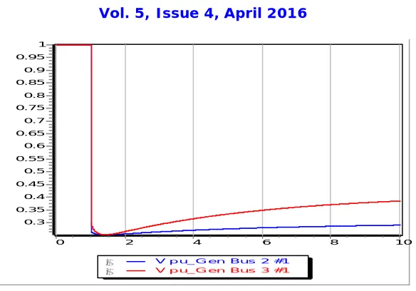
Simulation results of one generator is give in fig 6-7 . Generator bus voltage is decreased at the bus which bus is near to load closed to that generator bus this outage is not merely registered at farthest bus. Also the generator rotor angle are also given which shows generator rotor angle is increased because of local power need increase.
10 9 8 7 6 5 4 3 2 1 0 78 77 76 75 74 73 72 71 70 69 68 67 66 65 64 63 62 61 60
Frequen cy_Bus Bus 1 g
f
e
d
c
b gfedcb Frequen cy_Bus Bus 3gfedcb Freq uen cy_Bus Bus 7
10 9 8 7 6 5 4 3 2 1 1 0.95 0.9 0.85 0.8 0.75 0.7 0.65 0.6 0.55 0.5
V pu_Bus Bus 2 g
f
e
d
c
Fig 6. Generator voltage in case of one generator ouage
In Fig. 7 the generator current magnitude are given in case of one generator outage. The current magnitude is high changes in near generator close to outage generator and current magnitude close to unity.
Fig.7. Generator current magnitude
In the rotor angle at generator bus there is first in steady state after sometimes is decreased to initial state unity. But in case of generator outage at 2 the rotor angle is stable for first second and then decreases to zero. In case of generator 3 there is gradual decrease in rotor angle.
10 8
6 4
2 0
1 0.95 0.9 0.85 0.8 0.75 0.7 0.65 0.6 0.55 0.5 0.45 0.4 0.35 0.3
V p u_G en Bus 2 #1 g
f
e
d
c b
V p u_G en Bus 3 #1
g
f
e
d
c b
10 8
6 4
2 0
3.5
3
2.5
2
1.5
I pu_Gen Bus 3 #1 g
f
e
d
c b
I pu_Gen Bus 2 #1
g
f
e
d
Fig.8 Rotor angle during generator outage
X. SIMULATION OF SHORT CIRCUIT AT A BUS
Short circuit is cleared in 800ms. By setting this critical clearing time the disturbance occurs in this time is cleared instantly. This is also the longest time of short circuit results into stable operation after the post disturbance state. After this stage the voltage level is equals to pre- disturbance state.
Fig.8 Frequency of bus system versus time in case of short circuit
In case of short circuit at a bus there is critical time is set after which the system goes to steady state after clearing the fault. There is time set to 80 milliseconds. Bus voltage magnitude first increases after critical clearing time and after some time it is decrease and goes to steady state. At this instant there is gradual increase in bus voltage and gradual decrease.
10 8
6 4
2 0
35
30
25
20
15
10
5
0
Rotor Ang le_Gen Bus 2 #1
g
f
e
d
c
b
Rotor Ang le_Gen Bus 3 #1
g
f
e
d
c
b
10 9 8 7 6 5 4 3 2 1 0 66 65.5 65 64.5 64 63.5 63 62.5 62 61.5 61 60.5 60
Freq uen cy_Bus Bus 1 g
f
e
d
c
Fig.9. Bus voltage of other buses in case of short circuit of bus
XI.CONCLUSION
This paper presents the transient stability of IEEE 9 bus system in electric power system using power world simulator. In this stability testing generator and machine and surrounding elements are modeled as well. Its simulation results show that the system can withstand bus outage and generator outage and short circuit at bus and also retain its stability in electric power system. In case of bus outage represent that system is capable to fulfill load demand in case of blackout, as the disturbance occurs farthest in the system. As in the present rule the plant must stop in operation in case of blackout. The excitation in generation can also reduce the clearing time of fault and system can put into operation fast. Different models of generator and exciter are selected on the basis of its operation specified in library. The result of this simulation can help to generate the new methods to deal with transient problems.
REFERENCES
[1]Vedranajerkovic, ZeljkoSpoljaric , “Stability Testing of Small Biogas Plant in an Electric Power System”, International journal on Electrical and Computer Engineering System, Volume 2, Number 2, 2011.
[2]Manish N.Sinha1, Dr.B.R.Parekh, “Simulation of Voltage Sag Magnitude Estimation in a Power System Network”, International Journal of Advanced Research in Electrical, Electronics and Instrumentation Engineering (IJAREEIE) Gujarat,India February 2014 Vol. 3, Issue 2.
[3] RamandeepKaur, Er. Divesh Kumar, “Transient Stability Analysis of IEEE 9Bus system in Power World Simulator”, International journal on Electrical and Computer Engineering System,Vol.6, pp. 36-39, 2016.
[4] Manish N.Sinha1, Dr.B.R.Parekh, “Simulation of Voltage Sag Magnitude Estimation in a Power System Network” International Journal of Advanced Research in Electrical, Electronics and Instrumentation Engineering (IJAREEIE) Gujarat,India February 2014 Vol. 3, Issue 2.
[5] D. Jolevski, “Excitation System of Synchronous Generator,” University of Split, Faculty of Electrical Engineering, Mechanical Engineering and Naval Arhitecture, Split, 2009.
[6] V. Jerkovic, K. Miklosevic, Z.Spoljaric, “Excitation System Models of Synchronous Generator”, SIP 2010 28th International Conference Science in Practice, Subotica Tech – College of Applied Sci- ences, Subotica, Serbia, June 3-4, 2010, pp. 77-82.
[7] IEEE Power Engineering Society: “IEEE Recommended Practice for Excitation System models for Power System Stability Studies”, IEE Std. 421-5- 2005, IEEE New York, New York, 2006.
10 9 8 7 6 5 4 3 2 1 0 1.018 1.017 1.016 1.015 1.014 1.013 1.012 1.011 1.01 1.009 1.008 1.007 1.006 1.005 1.004 1.003 1.002 1.001 1 0.999 0.998 0.997 0.996
V pu_Bus Bus 2 g
f
e
d
c