39
RFID BASED AUTOMATIC CHALAN SYSTEM
Paramjeet Singh Kaler1, Sheetal Singh2, Shubhangi Singh3, Surendra Kumar Tripathi4
1.2.3. B-Tech Final Year Student 4. Associate Professor
Department of Electrical, Krishna Institute of Engineering and Technology (K.I.E.T) Ghaziabad, U.P., 201206, India
Abstract
RFID is an advanced technology which has been used for decades in military, hospitals, airlines, security, animal tracking and other areas. Many industries make use of RFID in various applications such as personal/ vehicle access control, logistics, equipment tracking etc. By this technology automatic identification of items is done using radio waves. There are numerous applications and implementations of this in past years. RFID tags have been developed to replace bar codes. These RFID tags can be read wireless and also contain more information as compared to bar codes. RFID tag is much more superior to a bar code as it can store information about manufacture, product type and can be identified without requiring line of sight. This paper presents the principles of RFID and also discuss its primary technologies and applications.
1. Introduction
A RFID technology is the system which constitutes one or more tags storing data and transferring that data to one or more readers over a wireless interface. This technology basically depends on the interaction between the RFID tags and RFID readers. Its operational frequency decides the range of reader[1]. There are many types of RFID, but mainly RFID devices are categorized into two classes: active and passive. Components of RFID include radio frequency.
Tags (transponders) and RF tag readers (transceivers).
This technology was in existence for more than decades, but then too it has not come into the mainstream. Why? The answer lies in its cost[9]. But now it is a critical cost point where with the added values it makes way for the large scale adoption by retail market companies.
This work is a design to provide a survey of the present developments in this field and to develop a framework which will facilitate to identify future guidance of research. This work will deal with the basic concept involved, functioning, principle and future growth[5-4].
2. HISTORICAL BACKGROUND OF RFID
The “Identification friend or foe” was the first RFID application and it was used in Second World War by the British. The fighter planes and tanks were carrying the transponders and decision to attack was taken by reading units. All around the world this technology is still used in army[11].
The “Electronic article surveillance” was the first commercial RFID application. It was developed as a theft prevention system in seventies[17]. The tags storing a single bit was the basis of this technology. While the customers were leaving the stores that bit was read and if the bit was not unset a sound alarm would be actuated in the system. Later in seventies the RFID tags also stepped into the field of agriculture for example animal tagging.
40 The RFID reader is liable to power and interact with the RFID tag. The reader does this by generating a high frequency electromagnetic energy and a query signal. This energy is seized by tag antenna and transmits the tag’s unique ID to the reader.[2] The communication process between the reader and the tag is guided by certain protocols. Protocols ISO 15693 and ISO 18000-3 are for high frequency range and ISO 18000-6 and EPC are for ultra-high frequency range. These protocols act on definite frequency bands: 860-915 MHz for UHF and 13.56 MHz for HF[10]. These protocols actuate the identification process when the reader is active. If the RFID reader is active and the RFID tags arrives, then it consequently activates and decodes the signal from the reader and responds back after doing certain modulation in reader’s field. Since all the tags in a reader’s range may respond simultaneously, the reader must be able to singulate a particular tag[3].
This necessitates an anti-collision algorithm. This facilitates the reader to handle each tag separately on the basis of frequency range. This is how reader performs reading and writing functions one by one on each tag[8].
4. BASIC COMPONENTS
The basic components of an RFID device is as follows:
1. Tags
2. Reader 3. Antenna
TAGS
The RFID tags which is also known as transponder is latched onto the objects which are to be identified. Depending upon the type and application, each RFID tag has certain internal memory, which can either be ‘read only’ type or ‘rewrite’ type. This memory is configured so so as to store the objects information to which the tag is attached, for example the product’s unique ID etc. the RFID tags can broadly be divided as active and passive tags[12]. The active tags are powered by an integrated battery while the passive tags are powered through a radio frequency signal from the transceiver inductively. Passive RFID are considered to be more feasible as they don’t require batteries.
READERS
The RFID reader, which is also known as a transceiver is used to read and write on the tag. A magnetic field is generated by the RFID reader which also the RFID system to detect the objects through the tag that come in reach of the range[18]. The reader produces a high frequency electromagnetic energy and query signal which prompts the tags to respond the query. This is how the transponder and the transceiver interact[14].
ANTENNA
The antenna acts as a channel between the transponder and the transceiver which governs the device’s communication and data acquisition. Radio signals are produced by the antenna to actuate the tag perform the read/ write operation over it[16]. For the operation of an RFID system, the reader should be quite responsive and sensitive so that it can capture tag’s feeble response, while the tag must receive a signal of ample power from reader.
The coupling of the tag and the reader can be done in two ways: through reactive coupling or by promulgation of an electromagnetic field or electromagnetic wave capture. The former is called near field coupling and the latter is called far field coupling. Near field coupled systems use inductive coupling. Its basis is Faraday’s principle of electromagnetic induction. Whereas, ‘line-of-site’ readings are needed fir far field coupled systems[6-7].
41
5. APPLCATION
RFID has various security and control applications. Through this a check can be kept on an individual actions like the length of stay and the record could be maintained of the same[13].
Tagging different medical objects like various equipment and patients’ files contribute to better health care applications
Other applications include RFID based library management, automatic challan system, traffic toll collections, supply chain and logistics, smarts cards, for identifying attack ranges etc.
6. Tables and Figures
Table no. 1 shows the opertaion of the RFID system when different RFID tags come in range of the RFID reader.
Table 1: Operations on different RFID tags
VEHICLE STATUS ACTION
CAR 1 Authorized Gate opens and
challan is cut
CAR 2 Authorized Gate opens and
challan is cut
42
Fig. 1 An RFID system
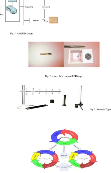
Fig. 2. A near field coupled RFID tags.
Fig. 3. Antenna Types
43
Figure 5. Circuit of RFID based Automatic Challan System
7. RESULT
Related to RFID technology we worked on one of its most eminent applications ,which is automatic challan system . In this project all the RFID components were used that is antenna ,tags ,readers ,etc. The whole system works very efficiently and fastly within a matter of seconds the challan money is deducted. This automated system reduce human effort and paperwork in addition to the time saving aspect.
Identification number of the authorized vehicles tags are stored in the memory of 8051. Only those authorized are permitted to enter. While the unauthorized tags identification number is not present in memory and no action is taken. To automatically detect tags from a distance the range of the antenna of the RFID reader should be large. The circuit we have used for this has a low frequency reader with a small range of 5 cm. For long range detection of RFID tags, active tags in addition with high frequency reader should be used.
8. CONCLUSION AND FUTURE SCOPE
One of the greatest contribution as well as development of 21st century can be referred to the RFID. RFID technology has opened new volumes in the field of security, reliability and accuracy in organisation and companies. This technology is efficacious enough to become ubiquitous in coming days. In percent time, it is already prosperous in many fields for the tracking purposes. There is a big scope for this technology in coming future. The advancements in fabrication of circuits and manufacturing of RFID will lessen the cost and thus allowing the more resources to be planned for security features. With the advent of new technology more features are embodied into tags, smart cards, the line between RFID components and general purposes computers will become obscure.
References
[1]http://www.cs.rutgers.edu/~badri/553dir/papers/MCPaperFinal-coldetect.pdf
[2] B. Glover, & H. Bhatt, RFID paper Essentials, O’Reilly Media, Inc, Sebastopol, (2006).
[3] Chatterjee, S. (2006) “A Taxonomy for RFID.” In Sprague place at the Proceedings of 39th IEEE HICSS. [4] Heder, S.H.M., Silvadurai, V., Brandon, and Vetharatnam, G. (2005) "Basics
44 [10] All datasheets from www.datasheetcatalog.com
[11] About AT89s8252 from www.atmel.com and www.triindia.co.in
[12] Martin Abadi, Michael Burrow, C. Kaufman and Butler W. Lampson authentication and delegation with smart cards.
In Theoretical Aspects Of Computer Software.
[13] Ross Anderson and Markus Kuhn. In IWSP : international workshop and security protocols, LNCS, 1997 [14] Benny Bing. Broadband wireless access. Kluwer academic publishers,2000.
[15] CAST inc. AES and SHA-1 Krypto processor course.http://www.cast-line.com\ [16] EAN international and uniform code council.http://www.ean-int.org
[17] Suresh Chari, Charanteej Jutla, Josyula R.Row and Pankaj rohatagi. In second advanced encryption standard
candidate conference,1999.