Sensorless Speed Control and PFC For Brushless Dc Motor
P
1.
P
S.Arulmozhi, P
2.
P
G.Divya,P
3.
P
D.Nivedha,P
4.
P
C.Suganthi,P
5.
P
P.Velmurugan
P
1,2,3,4
P
UG Student, P
5
P
Assistant Proffessor Department of Electrical and Electronics Engineering
Narasu’s Sarathy Institute of Technology Salem, India.
U
[email protected]
U,
U[email protected],
[email protected]
U,
U[email protected], [email protected].
ABSTRACTIn this paper we are designing a low cost microcontroller based speed control and power factor correction of BLDC motor without using any sensor. Brushless dc (BLDC) motors are commonly used in space application for its simplicity and high reliability. The hardware project is designed to control the speed and power factor correction of a BLDC motor using closed loop control technique. BLDC motor has various application used in industries like in drilling, lathes, spinning, electric bikes etc. The speed control of the DC motors is very essential. This proposed system provides a very precise and effective speed control system. The user can enter the desired speed and the motor will run at that exact speed. The power factor also corrected by using PWM modulator. We can see the animation of the speed using SCADA (LAB VIEW software).
1. INTRODUCTION
A BLDC motor has three phase windings on the stator and permanent magnets on the rotor. The BLDC motor is also known as an electronically commutated motor because an electronic commutation based on rotor position is used rather than a mechanical commutation which has disadvantages like sparking and wear and tear of brushes and commentators. The use of the brushless direct current (BLDC) motor in these applications is becoming very common due to
features of high efficiency, high flux density per unit volume, low maintenance requirements, and low electromagnetic-interference problems. These BLDC motors are not limited to household applications, but these are suitable for other applications such as medical equipment, transportation, HVAC, motion control, and many industrial tools .Efficiency and cost are the major concerns in the development of low-power motor drives targeting household applications such as fans, water pumps, blowers, mixers, etc.
2. EXISTING SYSTEM
Power quality problems have become important issues to be considered due to the recommended limits of harmonics in supply current by various international power quality standards such as the International Electro technical Commission (IEC) 61000-3-2 . For class-An equipment (< 600 W, 16 A per phase) which includes household equipment, IEC 61000-3-2 restricts the harmonic current of different order such that the total harmonic distortion (THD) of the supply current should be below 19%. A BLDC motor when fed by a diode bridge rectifier (DBR) with a high value of dc link capacitor draws peaky current which can lead to a THD of supply current of the order of 65% and power factor as low as 0.8 . Hence, a DBR followed by a power factor corrected (PFC) converter is utilized for improving the
power quality at ac mains. Many topologies of the single-stage PFC converter are reported in the literature which has gained importance because of high efficiency as compared to two-stage PFC converters due to low component count and a single switch for dc link voltage control and PFC operation .The choice of mode of operation of a PFC converter is a critical issue because it directly affects the cost and rating of the components used in the PFC converter. The continuous conduction mode (CCM) and discontinuous conduction mode (DCM) are the two modes of operation in which a PFC converter is designed to operate. In CCM, the current in the inductor or the voltage across the intermediate capacitor remains continuous, but it requires the sensing of two voltages (dc link voltage and supply voltage) and input side current for PFC operation, which is not cost-effective. On the other hand, DCM requires a single voltage sensor for dc link voltage control, and inherent PFC is achieved at the ac mains, but at the cost of higher stresses on the PFC converter switch; hence, DCM is preferred for low-power applications .The conventional PFC scheme of the BLDC motor drive utilizes a pulse width-modulated voltage source inverter (PWM-VSI) for speed control with a constant dc link voltage. This offers higher switching losses in VSI as the switching losses increase as a square function of switching frequency. As the speed of the BLDC motor is directly proportional to the applied dc link voltage, hence, the speed control is achieved by the variable dc link voltage of VSI. This allows the fundamental frequency switching of VSI (i.e., electronic commutation) and offers reduced switching losses. The parameters of the BL buck–boost converter are designed such that it operates in discontinuous inductor current mode (DICM) to achieve an inherent power factor correction at ac mains. The speed control of BLDC motor is achieved by the dc link voltage control of VSI using a BL buck–boost converter. This reduces the switching losses in VSI due to the low frequency operation of VSI for the electronic commutation of the BLDC motor. The performance of the
proposed drive is evaluated for a wide range of speed control with improved power quality at ac mains. Moreover, the effect of supply voltage variation at universal ac mains is also studied to demonstrate the performance of the drive in practical supply conditions. Voltage and current stresses on the PFC converter switch are also evaluated for determining the switch rating and heat sink design. Finally, a hardware implementation of the proposed BLDC motor drive is carried out to demonstrate the feasibility of the proposed drive over a wide range of speed control with improved power quality at ac mains.
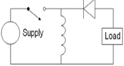
FIG.1 EXISTING SYSTEM
3. PROPOSED SYSTEM
The control methods based on an a-priori sensitivity analysis of the DN buses in order to calculate the sensitivity co-efficient of the DG units that allow changing voltage values on the BSP by means of reactive (or active) power. This result is achieved by applying a decentralized voltage control up to capability curves limits by means of the reactive power provided by power inverters or through a reduction of the active power (backup solution). On the contrary, in the proposed control, if the local reactive power compensation based on the sensitivity analysis fails (the reactive power reaches the availability limits) then IPP performs a coordinated regulation of the reactive powers
among the RES units. The aim is to avoid their disconnections due to voltage limit violation increasing the total power fed into the grid. It is worthy to highlight that only in this second case the proposed coordinated approach involves also the DSO during the control, which provides the power system state in order to develop the coordinated control.
In detail, from an operational point of view, the coordinated regulation of the reactive power can be divided in three steps:
1) DSO sends data of DN state to IPP.
2) IPP Control Centre (IPPCC) processes data estimating the power set points (active and reactive power) of each RES unit in order to control the voltage profiles within the limits taken into account.
3) Each generator changes the actual power set point with the new one received by IPPCC. Therefore, the core of the control described so far is carried out by IPPCC that has to solve a constrained optimization problem to have the regulation set point.
4. BLOCK DIAGRAM
Fig.no.2
Block
diagram
for
proposed system
5. REQUIRED TOOLS
5.1BUCK-BOOST CONVERTER
Two different topologies are called buck–boost converter. Both of them can produce an output voltage much larger (in absolute magnitude) than the input voltage. Both of them can produce a wide range of output voltage from that maximum output voltage to almost zero.
The inverting topology – The output voltage is of the opposite polarity as the input 31T
buck
(step-down) converter
31T followed by a 31Tboost
(step-up) converter
31T – The output voltage is of thesame polarity as the input, and can be lower or higher than the input. Such a non-inverting buck-boost converter may use a single inductor that is used as both the buck inductor and the boost inductor.
The buck–boost converter is a type of 31T
DC-to-DC converter
31T that has an output voltagemagnitude that is either greater than or less than the input voltage magnitude. It is a 31T
switched-mode power supply
31T with a similar circuittopology to the 31T
boost converter
31T and the 31Tbuck
converter
31T. The output voltage is adjustablebased on the 31T
duty
cycle
31T of the switching transistor. One possible drawback of this converter is that the switch does not have a terminal at ground; this complicates the driving circuitry. Also, the polarity of the output voltage is opposite the input voltage. Neither drawback is of any consequence if the power supply is isolated from the load circuit (if, for example, the supply is a battery) as the supply and diode polarity can simply be reversed. The switch can be on either the ground side or the supply.AC
SU
BL
DC
4 –
S
BI
DG
FU
ZZ
PI
CO
N
Figure 3General Circuit Diagram
5.2POWER INVERTER:
A power inverter, or inverter, is an electronic device or circuitry that changes direct current (DC) to alternating current (AC) .The input voltage, output voltage and frequency, and overall power handling, are dependent on the design of the specific device or circuitry. A power inverter can be entirely electronic or may be a combination of mechanical effects (such as a rotary apparatus) and electronic circuitry. Static inverters do not use moving parts in the conversion process.
Typical applications for power inverters include:
Portable consumer devices that allow the user to connect a battery, or set of batteries, to the device to produce AC power to run various electrical items such as lights, televisions, kitchen appliances, and power tools.
Use in power generation systems such as electric utility companies or solar generating systems to convert DC power to AC power.
Use within any larger electronic system where an engineering need exists for deriving an AC source from a DC source.
5.3PWM GENERATOR
Generate pulses for a carrier-based pulse width modulator (PWM).The PWM Generator block generates pulses for carrier-based pulse width modulation (PWM) systems. The block can be used to fire the self-commuted devices (FETs,
GTOs, or IGBTs) of single-phase, two-phase, three-phase, or a combination of two three-phase bridges.
The number of pulses generated by the PWM Generator block is determined by the number of bridge arms you have to control:
Two pulses are generated for a one-arm bridge. Pulse 1 fires the upper device and pulse 2 fires the lower device (shown for the IGBT device).
Fig.no. 4 PWM generator for 4 pulses
Four pulses are generated for a two-arm
bridge. Pulses 1 and 3 fire the upper
devices of the first and second arm.
Pulses 2 and 4 fire the lower devices.
Fig.no.5 PWM generator for 6
pulses
Six pulses are generated for a three-arm bridge. Pulses 1, 3, and 5 fire the upper devices of the first, second, and third arms. Pulses 2, 4, and 6 fire the lower devices.
Fig.no. 6 PWM generator for 6 pulses
Twelve pulses are generated for a double three-arm bridge. The first six pulses (1 to 6) fire the six devices of the first three-arm bridge and the last six pulses (7 to 12) fire the six devices of the second three-arm bridge.
The pulses are generated by comparing a triangular carrier waveform to a reference sinusoidal signal. The reference signal can be generated by the PWM generator itself, or it can be generated from a signal connected at the input of the block. In the second option, the PWM Generator needs one reference signal to generate the pulses for a single- or a two-arm bridge, or it needs a three-phase reference signal to generate the pulses for a three-phase bridge (single or double bridge). The amplitude (modulation), phase, and frequency of the reference signals are set to control the output voltage (on the AC terminals) of the bridge connected to the PWM Generator block. The pulses that fire the two devices of an arm bridge are complementary one to the other; for example, the pulse 4 is low (0) when the pulse 3 is high (1). This is illustrated in the next two
figures.
Fig.no.7 PWM generator waveform
for 2 pulses
The triangular carrier signal is compared to the
sinusoidal reference signal. Each time the two
signals become equal (at each crossing point),
the value of the pulses passes from 0 to 1, or 1 to
0, depending on their previous value.
The following figure displays the six pulses generated by the PWM Generator block when
programmed to control a three-arm bridge.
Fig.no.8 PWM generator waveform
for 6 pulses
Pulse 2 is the complement of pulse1, pulse 4 the
complement of pulse 3, and pulse 6 the
complement of pulse 5. Note that, unlike the
pulses generated by the Synchronized 6-Pulse
Generator block, the pulses generated by the
PWM Generator block are of variable width.
5.4POWER FACTOR CORRECTION
Power factor (P.F) is the ratio between actual powers to the apparent power.
Actual power/Apparent power.
P.F=Kw /Kva.
For a purely resistive load the power factor is unity. Active and reactive power are designated by P &Q respectively. The average power in a circuit is called active power and the power that supplies the stored energy in reactive elements is called reactive power.
Active Power:
Also known as “real power” or simply “power.” Active power is the rate of producing, transferring, or using electrical energy. It is measured in watts and often expressed in kilowatts (KW) or megawatts (MW). The terms “active” or “real” power are used in place of the term “power” alone to differentiate it from “reactive power.
Apparent Power:
The product of the voltage (in volts) and the current (in amperes). It comprises both active and reactive power. It is measured in “volt-amperes” and often expressed in “ kilovolt-amperes” (KVA) or “megavolt-kilovolt-amperes” (MVA).
Inductive loads cause the current to lag behind the voltage. The wave forms of voltage and current are then "out of phase" with each other. The more out of phase they become then the lower the Power Factor. Power Factor is usually expressed as Cos Phi. (Ø)Consider a canal boat being pulled by a horse. If the horse could walk on water then the angle (Phi) Ø would be zero and COSINE Ø=1. Meaning all the horse power is being used to pull the load. However the relative position of the horse influences the power. As the horse gets closer to the barge, angle Ø1 increases and power is wasted, but, as the horse is positioned further away, then angle Ø2 gets closer to zero and less power is wasted.
5.5THE ROLE OF FUZZY SYSTEMS IN CONTROL
Regarding a fuzzy system as either an approximate reasoned or functional approximate, it can be utilized in various ways in control systems. The block diagram of FLC is shown in Figure 4.1. Instead of directly issuing the control signals, the function of fuzzy system lies in monitoring a low level direct controller by outputting appropriate parameters to be used
by the direct controller. The decision taken by the supervisor can be based on the current control performance or the operating conditions depending on the control strategies employed in the system. By treating fuzzy system as a representative model of the controller plant, third usage of the fuzzy system can be found, which is to place it into the various model based control structures found in traditional model.
Figure 9 Block Diagram of Fuzzy Logic Controller
5.6FUZZY LOGIC IN BUCK-BOOST CONVERTER
In the proposed FLC design, the Voltage (V) and Current (I) are considered as the linguistic variables and the duty cycle as the linguistic output variable. The process control can be described with the above linguistic variables as follows:
Vpv(k) = [Vpv(k-1) + Vpv(k-2)]/2
Ipv(k) = [Ipv(k-1) + Ipv(k-2)]/2
Both input and output vectors are defined in the universe of discourse as
e(k)={x1,µe(x1)/x1 Є U1; µe(x1) Є (-1,1)} Δe(k)={x2,µΔe(x2)/x2 Є U2; µΔe(x2)
Є (-1,1)}
u(k)={v,µu(v)/v Є U; µu(v) Є (-1,1)
Fuzzy rules were developed heuristically to facilitate the shaping of loop formation and simplify the controller tuning.
Each fuzzy rule RI defines a fuzzy implication li1*li2→wi, which is a fuzzy set defined in the product space U*R. That is,
µRI(x1,x2,u)=f→[(µAi1(x1),µAi2(x2),µAiu(u)]
Where, Ai1, Ai2, and Aiu denote fuzzy sets for x1, x2 and u respectively. The used fuzzy implications rules in this work are minimum operation rule and production operation rule.
6. CIRCUIT DIAGRAM
Fig.no.10
Circuit diagram for
proposed system
6.1 WORKING
Ac supply is given to the rectifier, which is used to convert AC-DC. Separately we can measure the voltage and current from the power supply for correcting the power factor and it given to the PWM converter. PWM is used to vary the pulse depends on the duty cycle 50%. It will act as buck/boost for correcting the power factor and PWM pulse is given to the DC-DC converter for power factor maintains. PWM pulse is given to the inverter for speed
controller. Rectifier output is given to the DC-DC converter, which is used to convert fixed DC-DC to variable DC. Its output is given to the inverter it will change DC to AC. So the supply is given to the BLDC motor and its start rotate. Measuring the current from inverter and it’s given to the fuzzy logic controller. Using fuzzy logic algorithm, it can control the speed and it will display on the LCD. We can see the animation of speed of the motor and power factor in SCADA (lab view software).
7. CONCLUSION
A PFC BL buck–boost converter-based VSI-fed BLDC motor drive has been proposed targeting low-power applications. A new method of speed control has been utilized by controlling the voltage at dc bus and operating the VSI at fundamental frequency for the electronic commutation of the BLDC motor for reducing the switching losses in VSI. The front-end BL buck–boost converter has been operated in DICM for achieving an inherent power factor correction at ac mains. A satisfactory performance has been achieved for speed control and supply voltage variation with power quality indices within the acceptable limits of IEC 61000-3-2. Moreover, voltage and current stresses on the PFC switch have been evaluated for determining the practical application of the proposed scheme. Finally, an experimental prototype of the proposed drive has been developed to validate the performance of the proposed BLDC motor drive under speed control with improved power quality at ac mains. The proposed scheme has shown satisfactory performance, and it is a recommended solution applicable to low-power BLDC motor drives.
8. REFERENCES
C. L. Xia, Permanent Magnet Brushless DC Motor Drives and Controls.
Hoboken, NJ, USA: Wiley, 2012.
J. Moreno, M. E. Ortuzar, and J. W. Dixon, “Energy-management system for a hybrid electric vehicle, using ultra capacitors and neural networks,”
IEEE Trans. Ind. Electron., vol. 53, no. 2, pp. 614–623, Apr. 2006.
Y. Chen, C. Chiu, Y. Jhang, Z. Tang, and R. Liang, “A driver for the single phase brushless dc fan motor with hybrid winding structure,” IEEE Trans.Ind. Electron. vol. 60, no. 10, pp. 4369–4375, Oct. 2013.
X. Huang, A. Goodman, C. Gerada, Y. Fang, and Q. Lu, “A single sided
matrix converter drive for a brushless dc motor in aerospace applications,” IEEE Trans. Ind. Electron., vol. 59, no. 9, pp. 3542–3552, Sep. 2012.
H. A. Toliyat and S. Campbell, DSP-Based Electromechanical Motion Control. Boca Raton, FL, USA: CRC Press, 2004. P. Pillay and R. Krishnan, “Modeling of permanent magnet motor drives,”
IEEE Trans. Ind. Electron., vol. 35, no. 4, pp. 537–541, Nov. 1988.
Limits for Harmonic Current Emissions (Equipment Input Current ≤16 A
Per Phase), Int. Std. IEC 61000-3-2, 2000.
S. Singh and B. Singh, “A voltage-controlled PFC Cuk converter based
PMBLDCM drive for air-conditioners,” IEEE Trans. Ind. Appl., vol. 48,
no. 2, pp. 832–838, Mar./Apr. 2012.
B. Singh, B. N. Singh, A. Chandra, K. Al-Haddad, A. Pandey, and
D. P. Kothari, “A review of single-phase improved power quality acdc
converters,” IEEE Trans. Ind. Electron., vol. 50, no. 5, pp. 962–981,
Oct. 2003.
B. Singh, S. Singh, A. Chandra, and K. Al-Haddad, “Comprehensive
study of single-phase ac-dc power factor corrected converters with
High-frequency isolation,” IEEE Trans. Ind. In format. vol. 7, no. 4,
pp. 540–556, Nov. 2011.
S. Singh and B. Singh, “Power quality improved PMBLDCM drive
For adjustable speed application with reduced sensor buck-boost PFC converter,” in Proc. 4th ICETET, Nov. 18–20, 2011, pp. 180– 184.
T. Gopalarathnam and H. A. Toliyat, “A new topology for unipolar brushless dc motor drive with high power factor,” IEEE Trans. Power Electron.,vol. 18, no. 6, pp. 1397–1404, Nov. 2003.
Y. Jang and M. M. Jovanovich, “Bridgeless high-power-factor buck converter,” IEEE Trans. Power Electron., vol. 26, no. 2, pp. 602–611,
Feb. 2011.
L. Huber, Y. Jang, and M. M. Jovanovi´c, “Performance evaluation of bridgeless PFC boost rectifiers,” IEEE Trans. Power Electron., vol. 23,
no. 3, pp. 1381–1390, May 2008.
A. A. Fardoun, E. H. Ismail, M. A. Al-Saffar, and A. J. Sabzali, “New ‘real’ bridgeless high efficiency ac-dc converter,” in Proc. 27th Annu.
IEEE APEC Expo., Feb. 5–9, 2012, pp. 317–323.