Generation Optimization Using Two Area
Control
Ramneet Kour
1PG Student [Power System], Dept. of EEE, Lovely Professional University, Phagwara, Punjab, India2
ABSTRACT: This paper presents that the use of electricity and its need has been increased. Thus, in order to ensure the consumers with reliable and continuous supply during the increase of demand, need of interconnection between the different generating areas are required and due to this reason the concept of Automatic Generation Control is taken into consideration which is then used for adjusting the output power of various generators at different power plants in an electric power system. A controller based on Particle Swarm Optimization has been designed in order to keep the frequency deviations due to change in load in either of the area at a minimum level i.e. by keeping the frequency at its set value of 5o Hz and power transfer through tie-line uniform.
KEYWORDS: Automatic Generation Control (AGC), ParticleSwarm Optimization (PSO).
I.INTRODUCTION
Due to change in demand or load in a large interconnected power system, power flow between the areas connected by the tie line and system frequency is greatly affected and thus to provide users with consistent and excellent supply of electric power, power system have to maintain balance between power demand and power generation. Thus now days for providing stable operation of the power system and minimizing the frequency deviation due to generation loss in either of the area, Automatic Generation Control (AGC) is provided.
For adjusting the output power of various generators at different power plants in an electric power system, in response to change in load, a system called as Automatic generation controlled is employed. AGC also denoted as Load frequency control. Adjustments to output of generators and moment by moment balancing of load and generation are prime requirements of the power grid. By measuring the system frequency we can judge the balance of the system i.e. if the system frequency is increasing there is generation of more power than used one and there is acceleration of all the machines in the system. If it is decreasing, all the system generators are slowing down and there should be more loads on the system than the instantaneous generation can provide.
In a system, one generating unit would be designed as the regulating unit and to control the balance between generation and load to maintain system frequency at desired level, it would be manually adjusted before the use of Automatic Generation Control. With speed droop to proportion their share of the load according to their ratings the remaining units can be controlled. In an automatic system, many units can participate in stability, economy, regulation, reducing wear and tear on a single unit controls and improving system efficiency.
For adjacent control areas grid has tie line interconnections and to maintain the power interchanges over the tie-line at scheduled levels, Automatic Generation Control is used. Automatic Generation Control can take into account such matters as the most economical units to adjust, the coordination of hydroelectric, thermal and other generation type and even constraints related to the stability of the system and capacity of interconnections to other power grids with the help of computer based solutions and multiple inputs. To control the allocation of the generator so as to maintain frequency and net interchange of power through transmission lines are the main functions of AGC under sudden varying load conditions.
II.
PROBLEM FORMULATIONknow frequency of a power system wholly depends upon the speed at which the generators are rotated by their prime movers. Therefore frequency control is basically a matter of speed control of machines in the generating stations. Prime movers of all the turbines like steam or hydraulic are provided with speed governors in order to control the speed (frequency) at rated value.
In the AGC interconnected system with two areas, varieties of AGC schemes are employed like control, optimal, self-tuning and adaptive, intelligent. These schemes are usually employed in order to decide the parameters of the controllers and then this controller is employed in the model to ensure less deviation of the frequency from its set value and also to ensure proper transferring of power between the two interconnected areas.
Numerous types of controllers like PI, PID and Conventional controllers are provided to ensure proper working of the system which is interconnected but the problem related to these controllers is that they are very lazy in handling the disturbances which occurs in the system due to various conditions. Thus to avoid the problem related to these type of controllers, a controller is designed on the basis of PSO technique which proven to be perform better than these one’s.
III.SYSTEM DISCRIPTION AND MODELLING
III.OVERVIEW OF PSO TECHNIQUE
Basically Particle Swarm Optimization is a technique which can be employed for various fields of engineering like electrical for developing of efficient controllers and also in computer engineering field. In both the fields, solution of a given problem is optimized and a best possible solution is suggested from number of possible solutions in order to meet the desired characteristics in a power system. This PSO technique worked on the problem by considering the particle’s position and velocity from the number of possible solutions.
Based on the movement and clustering of birds and fishes, Eberhert and James Kennedy in 1995 give the concept of Particle Swarm Optimization (PSO). It usually employs the problem with a solution based on the societal communication. The main aim of the scientists is to check the behaviour, movement and gathering of birds and fishes around the food items and then start developing an algorithm which is basically a computer based software simulation. The basis of PSO is group cleverness and its effort of moving for a particular food source and finding the more efficient and quick way to the food items. It is a computational evolutionary idea for exploring the space which is to be searched.
Although PSO is very easy algorithm but it sounds very complex in some aspects. Various enhanced problems like non-regulating, loud and time changing are overcome by using PSO method for optimization. A flock of variables may have their own values adjusted closer to the member whose value is closest to the target at any given moment at the end of numerous iterations. Suppose a source of food is smelled by a gathering of birds which is out of sight is considered as an example for the description of the PSO technique. There is swinging of birds in the direction of the bird’s sound which is nearby to the food. Bird’s sound becomes more and louder if another group of birds came closer to the food item. Therefore, it is very modest and confortable to employ PSO as an algorithm. As in PSO technique very less amount of parameters are to be adjust so it is said to be very appealing technique in order to employed for AGC connected system.
There are usually three global variables of which this algorithm is to be taken into consideration:
Target conditions or values.
Global best (Gbest) is used to determine the particle which is presently nearer to the goal or target.
If the target isn’t found, the algorithm is stopped with the help of stopping value. Each particle in the PSO technique may comprise of:
A possible solution is represented by the data.
How much there is change in data is indicated by the velocity value.
A Personal best (Pbest) value indicating the closest the particles data has ever come to the target.
A basic variant of the PSO algorithm works by having a population (called a swarm) of candidate solutions (called particles). These particles are moved around in the search-space according to a few simple formulae. The movements of the particles are guided by their own best known position in the search-space as well as the entire swarm's best known position and then their movement is started. The two main equations of the PSO algorithms are given as below:
1. Velocity Modified Equation
Vik+1 = W Vik + C1rand1 × (Pbesti– Sik) + C2rand2 × (Gbesti- Sik)
Where, Vik = Velocity of agent I at iteration k W = Weighing function.
C1 = Weighing factor.
rand1 = Random number between 0 and 1. Pbesti= P best of agent i.
Gbesti = G best of the group. Si
k
First term:W Vik+1 are the inertia component responsibility for the movement of particle in the direction it was previously heading “W” has a vital impact on speed of its value and is less than speed up the convergence otherwise encouraging the exploration.
Second term:C1rand1 × (Pbesti– Sik) is the cognitive component acts as a particle memory.
Third term:C2rand2 × (Gbesti- Sik) is the social component which is the reason why the particle move to best region found safer by the swarm.
Once the calculation for velocity of each particle is done then the position can be updated using equation of position modification.
2. Position Modification Equation Sik + 1 = Sik +Vik + 1
Where, Sik + 1 and Sik represents modified and search points respectively. And, Vik+1 = Modified velocity.
This process is repeated until and unless some stopping criteria are applied.
IV. RESULT AND DISCUSSION
After the modelling of two interconnected area i.e. after the deciding of the controller parameters based on the proposed scheme it can be seen that the frequency deviations in the system due to change in loading conditions can be reduced to large extent and power through the tie line is also maintained.
RESULTS WITH AND WITHOUT CONTROLLER :
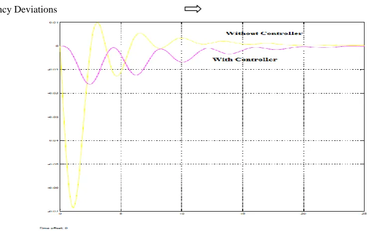
Frequency Deviations
Figure 1.1: Simulation Results With and Without Controller.
In the above graph, we can see that whenever variation i.e. changes in load occurs in the interconnected area; there must be large frequency deviations. However, after the implementation of controller based on proposed schemes these frequency deviations are seen to be in lesser amount.
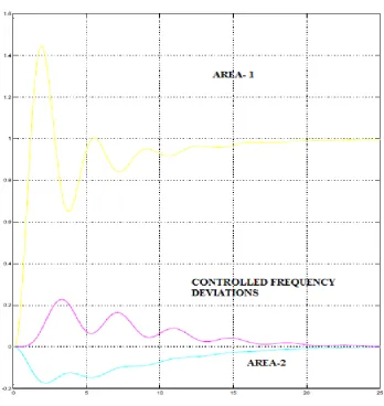
Frequency Deviations
Figure 2.2: When change occurs in one of the Area.
Below figure gives us the simulation results of an interconnected area, whenever sudden disturbance or transient in one of the area occurs due to generation loss and frequency deviations can be minimized when controller based on proposed scheme is applied.
V.CONCLUSION
In this thesis work, a controller based on Particle Swarm Optimization Technique (PSO) is designed and results are analysed with the help of MATLAB/ SIMULATION in order to justify the proposed scheme.
Initial step is to consider two areas which are connected with the help of a tie-line.
By applying proposed scheme, optimized parameters of the controller are decided.
Then, Model of the two interconnected areas is developed with the help of MATLAB.
REFERENCES
[1] M.L. Kothari, J. Nanda, D.P. Kothari and D. Das, “Discrete Mode of the Two Area Reheat Thermal System with New Control Error” IEEE Transactions on Power Systems, Vol. 4, No.2, May 1989.
[2] H.L. Zeynelgil, A. Demiroren, N.S. Sengor, “ The Application of ANN Technique to AGC for Multi- Area Power Systems” Electrical power and energy system 24(2002), 345-354.
[3] K.S.S. Ramakrishna, Pawan Sharma ,P.S. Bhatti, “Automatic Generation Control of Interconnected Power system with diverse sources of power generation” International Journal of Engg., Science and Technology, Vol.2,No.5,2010,pp-51-65.
[4] Swasti R. Khuntia and Sidharatha Panda,“Comparitive Study of Different Controllers for Automatic Generation Control of an Interconnected Hydro- Thermal System with Generation Rate Constraints”2010 International Conference on Industrial Electronics, Control and Robotics. [5] Naimul Hassan, Ibraheem and ShauibFarooq,” Real Time Simulation of Automatic Generation Control for Interconnected Power System”
International Journal on Electrical Engineering and Informatics- Volume 4, Number1, March 2012.