1645 |
P a g e
Monitoring and Controlling of Distribution Transformer
Using GSM Module (AVR Microcontroller Based)
Abdurrahman Shu’Aibu Hassan
Department of Electrical Engineering, Sharda University, G.Noida, (India)
ABSTRACT
This paper is about design and implementation of a mobile embedded system to monitor and record
key parameters of a distribution transformer like load current, oil level and ambient temperature. The
idea of on-line monitoring system integrates a global service mobile (GSM) Modem before any
catastrophic, with a standalone single chip microcontroller and different sensor. It is installed at the
distribution transformer site and above parameters are recorded using the analog to digital converter
(ADC)of the embedded system. The obtained parameter are processed and recorded in the system
memory.if any abnormality or an emergency situation occurs the system sends SMS (short message
service) messages to the mobile phone containing information about the abnormality according to
some predefined instructions programmed in the microcontroller. This mobile system will help the
transformers to operate smoothly and identify problems failure.
Keywords: Transformer, Microcontroller, Mobile (GSM), Digital Converter (ADC)
I. INTRODUCTION
In power systems, distribution transformer is electrical equipment which distributes power to the low-voltage
users directly, and its operation condition is an important component of the entire distribution network
operation. Operation of distribution transformer under rated condition( as per specification in their nameplate)
guarantees their long life .However, their life is significantly reduced if they are subjected to overloading,
resulting in unexpected failures and loss of supply to a large number of customers thus effecting system
reliability. Overloading and ineffective cooling of transformers are the major causes of failure in distribution
transformers. The monitoring devices or systems which are presently used for monitoring distribution
transformer havingnumbers and deficiencies. Few of them are mentioned below.
(1) Ordinary transformer measurement system generally detects a single transformer parameter, such as power,
current, voltage, and phase. While some ways could detect multi-parameter, the time of acquisition and
operation parameters is too long, and testing speed is not fast enough.
(2) Detection system itself is not reliable. The main performance is the device itself instability, poor
anti-jamming capability, low measurement accuracy of the data, or even state monitoring system should is no effect.
(3) Timely detection data will not be sent to monitoring centres in time, which cannot judge distribution
transformers three-phase equilibrium.
(4) A monitoring system can only monitor the operation state or guard against steal the power, and is not able to
1646 |
P a g e
(5) Many monitoring systems use power carrier communication to send data, but the power carriercommunication has some disadvantages: serious frequency interference, with the increase in distance the signal
attenuation serious, load changes brought about large electrical noise. So if use power carrier communication to
send data, the real-time data transmission, reliability cannot be guaranteed. According to the above
requirements, we need a distribution transformer real-time monitoring system to detect all operating parameters
operation, and send to the monitoring centre in time. It leads to online monitoring of key operational parameters
of distribution transformers which can provide useful information about the health of transformers which will
help the utilities to optimally use their transformers and keep the asset in operation for a longer period. This will
help to identify problems before any serious failure which leads to a significant cost savings and greater
reliability. Widespread use of mobile networks and GSM devices such GSM modems and their decreasing costs
have made them an attractive option not only for voice media but for other wide area network applications.
Therefore a proposed solution is chosen to develop a microcontroller based transformer overload protection
prototype because the microprocessors based relays provides greater flexibility, more adjustable characteristics,
increased range of setting, high accuracy, reduced size, and lower costs, along with many ancillary functions,
such as control logic, event recording, fault locat
ion data, remote setting, self-monitoring and
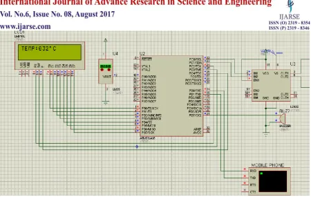
checking, etc.(Blackburn,2006).II. SYSTEM DESIGN:
2.0 Interfacing module scheme
The
figure
1647 |
P a g e
At the primary side of the 230:160VAC transformer, a step down 230-12VAC transformer is rectified to a pure5VDC and feed into the ADC pin of the microcontroller for monitoring the voltage of the transformer.
At the secondary side of the transformer, a current sensor is connected in series between the load and the
transformer secondary terminal for sensing, the load current, output of the current sensor is then feed to the
microcontroller ADC pin for monitoring. The LCD is used to display the transformer voltage, current and
temperature, similarly the personal computer is used to display the transformer parameters for monitoring
purpose. While monitoring the transformer parameters, whenever the load current exceeds the transformer rated
current, the microcontroller detects an overcurrent faults and it sends a trip signal to the overcurrent relay,
thereby protecting the transformer from blowing off. Moreover, when the autotransformer secondary is varied
above the specific limit, the microcontroller detects an overvoltage faults and it sends a trip signal to the
overvoltage protective relay, thereby protecting the transformer and the loads from blowing off.
2.1 COMPONENT DETAILS
Based on the various reviews conducted on transformer protection and the above block diagram which was
conceived out of those literature reviews conducted, Numbers of components are required in developing the
protection system.
2.2 MICROCONTROLLER
The microcontroller is required to serve the purpose monitoring the transformer information such as
temperature, voltage and current through the LCDdisplay, personal Gsm module and triggering the relay when
there is any fault. Modern power networks require faster, more accurate and reliable protective schemes.
Microcontroller-based protective schemes are capable of fulfilling these requirements. They are superior to
electromagnetic and static relays. These schemes have more flexibility due to their programmable approach
when compared with the static relays which have hardwired circuitry. Therefore in order to achieve this task the
ATmega16 microcontroller was chosen because of its suitability for this project such as speed, power
consumption, universal synchronous asynchronous receiver transmitter (USART) functionality, in builtADC,
and amount of RAM and ROM on the chip. The ATmega16 is a low-power CMOS 8-bit microcontroller based
on theAVR enhanced RISC architecture. It has a High Endurance Non-volatile Memory segments such as 32K
Bytes of In-System Self-programmable Flash program memory,1024 Bytes EEPROM, 2K Byte Internal SRAM,
write/erase Cycles: 10,000Flash/100,000 EEPROM [4]-[5].
The ATmega32 microcontroller I/O pins are 40 in number, and most of them can be used as I/O pins. The
input/output pinsserves the purpose of connecting the ADC
chip, LED, LCD display, alarm buzzer and in this case the port A, pin one, two and three were used to take care
of ADC input since we are using three different analogue signals ne for the voltage transformer other for the
1648 |
P a g e
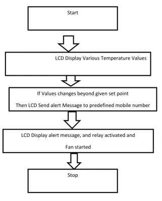
2.3 FLOW CHART OF THE SYSTEM
Figure 1.1
Figure 2.3
The Diagram above explain the details of the flow chart of the system design, initial reads the start and Display
the various values of the temperature on the Led ,if the current set value of the temperature is crossing the set
value, it activate the relay and the buzzer alarm starts blowing and the fans turn on.
An alert Message is send to the predefined defined number defines on the microcontroller program so that
necessary action is taken.
2.4 VOLTAGE TRANSFORMER
The 230VAC:12VAC step down voltage transformer is used to measure the load voltage. The voltage
transformer will pass through rectification process before fed to The ADC.
Start
LCD Display Various Temperature Values
If Values changes beyond given set point
Then LCD Send alert Message to predefined mobile number
LCD Display alert message, and relay activated and
Fan started
1649 |
P a g e
The above calculation shows that the step down transformer has step up theprimary current from 0.667 to 1A at the secondary
2.5 OVER VOLTAGE PROTECTION CIRCUIT DESIGN CALCULATIONS.
The secondary voltage of the transformer is 160VAC and connected to a
bridge rectifier, therefore the DC output is approximately:
From equation 3, the VAC is the RMS transformer voltage and the 0.7V is the
voltage drop across the rectifier. As there are two diodes conducting for each half cycle, therefore there will be
two rectifier voltage.
2.6 RELAY
The relay is an electrically controllable switch widely used in industrial controls, automobiles, and appliances. It
allows the isolation of two separate sections of a system with two different voltage sources. For example, a +5V
system can be isolated from a 120V system by placing a relay in between them. One such relay is called an
electromechanical or electromagnetic relay EMR as shown in figure 3.4. The EMRs have three components: the
coil, spring and contacts. In Figure 3.4, a digital +5V can control a 230Vac lamp without any physical contact
between them. When current flows through the coil, a magnetic field is created around the coil (the coil is
energized), which causes the armature to be attracted to the coil. The armature‟s contact acts like a switch and
closes or opens the circuit. The relay serves as the protective device of the entire system. The relay receives trip
signal from the microcontroller and thereby cutting the transformer primary from the input ac source hence
protecting the transformer [13]-[14]-[15]-[16].
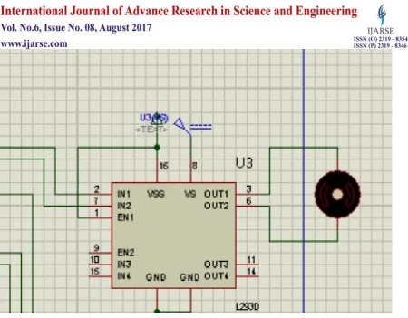
2.7 RELAY DRIVE CIRCUIT
Microcontroller pins lack sufficient current to drive a relay. While the 6volts relay‟s coil needs around 12mA to
be energized, the current is obtained by the V/R expression. For example, if the coil is 6VDC and the coil
resistance is 500Ω, a minimum of 12mA (6V/500Ω = 12mA) is need to energize the relay while the microcontroller‟s pin can provide a maximum of 1-2mA current, therefore a transistor was used as relay driver
1650 |
P a g e
Figure 2.7 shows relay driver circuit
2.8Cut-off condition
A transistor is said to be in cut-off region when the base emitter BE junction is not forward-biased. When is near
zero, approaches zero in a nonlinear manner, this is known as a cut-off region of operation. In this case the
transistor acts as an open or off switch.
2.9 Saturation condition
The transistor is said to be in a saturated condition when the BE base emitter junction is in forward biased, and
there is an enough base current to produce high
collector current. In this case the transistor is said to be closed or on. Saturation:
2
III. RESULTS AND DISCUSSIONS
3.1 Results
Nameplate rating of Distribution Transformer:
KVA rating: 500
1651 |
P a g e
Voltage rating:HV: 11KV
LV: 0.4KV
Current rating:
HV: 26.24A
LV: 666.70A 40
Impedance voltage: 3.92%
Vector Group: Dy11
Maximum Temperature Rise in oil: 45 deg.C
We need to monitor voltage and currents in phase.
Under normal condition
Ia=121.4A Vab=442.0V
Ib=108.8A Vbc=437.2V
Ic=138.5A Vca=440.3V
Taking the data of previous fault condition
Instantaneous load current in phases
Ia=318.6A
Ib=294.4A
Ic=333.1A
These currents of high magnitudes can‟t be fed directly to our designed system. It needs to be scaled down. For
this purpose current transformer and potential transformer can be used in practice. The current and voltage after
being scaled down is fed to microprocessor based system where it compares it with the reference value and take
consequent action.
Regarding taking reference value, we have to take account the normal current, turn ratio of CT and PT, accuracy
and associated errors. Comparing suchsituation using potentiometer. We will vary the voltage and current in
different phases.
The reference voltage is 2.44
By varying the potentiometer we change the voltage of phase 3 to 3.1
It is more than the reference voltage…
So the system will send message.
1652 |
P a g e
Figure 3.1
IV. SUMMARY AND CONCLUSION
The GSM based monitoring of distribution transformer is quite useful as compared to manual monitoring and
also it is reliable as it is not possible to monitor always the oil level, oil temperature rise, ambient temperature
rise, load current manually. After receiving of message of any abnormality we can take action immediately to
prevent any catastrophic failures of distribution transformers. In a distribution network there are many
distribution transformers and associating each transformer with such system, we can easily figure out whichof
Transformer is undergoing fault from the message sent to mobile. We don‟t need to check all transformers and
corresponding phase currents and voltages and thus we can recover the system in less time. The time for
receiving messages may vary due to the public GSM network traffic but still then it is effective than manual
monitoring.
REFERENCES
[1] Lei fried, T, “Online monitors keep transformers in service”, Computer Applications in Power, IEEE,
Volume:11 Issue: 3 , July 2009 Page(s):36 -42.
[2] Chan, W. L, So, A.T.P. and Lai, L., L.; “Interment Based Transmission Substation Monitoring”, IEEE
Transaction on Power Systems, Vol. 14, No. 1, February 2007, pp. 293-298.
[3] Par S. Tenbohlen,T. Stirl, M. Rösner,” Benefit of sensors for on-line monitoring systems for power transformers”
[4] T. D. Poyser, "An On-Line Microprocessor Based Transformer Analysis System to Improve the Availability
and Uti'lization of Power Transformers". IEEE Trans. On Power Apparatus and Systems, Volume
1653 |
P a g e
[5] Muhammad Ali Mazidi , Janice GillispieMazidi, RolinD.Mckinlay, The 8051 Microcontroller AndEmbedded Systems Using Assembly And Second Edition, Pearson Education, 2008, India.
[6] Microcontroller ATmega 16; www.atmel.com/Images/doc2466.pdf .
[7]Constantin Daniel Oancea,” GSM Infrastructure Used for Data Transmission”, 7th International Symposium
on Advanced Topics in Electrical Engineering (ATEE), 2011 May 12-14, Page(s): 1 – 4.
[8] AVR microcontroller for embedded system, ”Muhammad Mazidi”. [2] AVR Microcontrollers,” Milan Verle” [9] Datasheet of LM 35
[9] A. Karnik, “Performance of TCP congestion control with feedback: TCP/ABR and rate adaptive TCP/IP,”
M. Eng. Thesis, Indian Institute of Science, Bangalore, India, Jan. 1999. J. Padhye, V. Firoiu, and D.
Towsley, “A stochastic model of TCP Reno congestion avoidance and control,” Univ. Of Massachusetts,
Amherst, MA, CMPSCI Tech. Rep. 99-02, 1999.
[10] Wireless LAN Medium Access Control (MAC) and Physical Layer (PHY) Specification, IEEE Std. 802.11,
1997
[11] The Art of Programming Embedded Systems Jack G. Ganssle Academic press.
[12] Real-Time Systems and Their Programming Languages Alan Burns &Andy Welling‟s Addison-Wesley,
1990
[13] V.Thiyagarajan& T.G. Palanivel, (J2010) „An efficient monitoring of substations using microcontroller
based monitoring system‟ International Journal of Research and Reviews in Applied Sciences, 4 (1),
pp.63-68
[14] Ali Reza Fereidunian, MansoorehZangiabadi, MajidSanaye-Pasand, GholamPournaghi, (2003) „Digital
Differential Relays For Transformer Protection Using Walsh Series And Least Squares Estimators‟.
CIRED (International Conference on Electricity), pp. 1-6.
[15] Badri ram and D N Vishwakarma (1995) power system protection and switch gear New delhi: Tata
McGraw hill
[16] Mazouz A. SalaharAbdallah R. Al-zyoud (2010), „Modeling of transformer differential protection using
programmable logic controllers‟ European journal of scientific research, 41(3), pp. 452-459.
[17 ] S.M Bashi, N. Mariun and A.rafa (2007). „Power Transformer protection using microcontroller based
relay‟, Journal of applied science, 7(12), pp.1602-1607.
[18] V.Thiyagarajan& T.G. Palanivel, (J2010) „An efficient monitoring of substations using microcontroller
based monitoring system‟ International Journal of Research and Reviews in Applied Sciences, 4 (1),
pp.63-68.
[19] SuxiangQian, Hongsheng Hu, „Design of Temperature Moni-toring System for Oil-Immersed Power
Transformers based on MCU‟, on International Conference on Electronic Measurements and
Instrumentation (ICEMI), May 2009
[20] dong „A Transformer Online Monitoring and Diagnosis Em-bedded System Based on TCP/IP and Pub/Sub