28 | P a g e
Designing of BOOTH Multiplier using RADIX-4 to
Improve Path Delay
Himanshu Kr. Rai, Mrs. Uma Sharma
Electronics & Communication, AKJEC, Ghaziabad, AKTU (INDIA)
Electronics & Communication, AKJEC, Ghaziabad, AKTU (INDIA)
ABSTRACT
A Conventional Booth Multiplier consists of the Booth Encoder, the partial-product tree and carry propagate adder [2, 3]. Different schemes are addressed to improve the area and circuit speed effectively. This paper describes implementation of radix-4 Booth Multiplier and this implementation is compared with Radix-2 Encoder Booth Multiplier. This Implementation describes in the Form of RTL Schematic and Comparison is also done by using RTL Schematic and path delay.
Keywords : Adder, CLA, CSA, Booth multiplier, Radix
I. INTRODUCTION
Multipliers are key components of many high performance systems such as FIR filters, Microprocessor, digital signal processors, etc. A systems performance is generally determined by the performance of the multiplier because the multiplier is generally the slowest element in the system. Furthermore, it is generally the most area consuming. Hence, optimizing the speed and area of the multiplier is a major design issue however; area and speed are usually conflicting constraints so that improving speed results mostly in larger areas [5, 6].Booth Multiplier reduces number of iteration step to perform multiplication as compare to Conventional steps. Booth algorithm ‗scans‘ the multiplier operand and skips chains of This algorithm can reduce the number of additions required to produce the result compared to Conventional Multiplication algorithm, where each bit of the multiplier is multiplied with the multiplicand and the partial products are aligned and added together [4]. More interestingly the number of additions is data dependent, which makes this algorithm.
II. COMMON FEATURES OF MULTIPLIERS
(i) Counter-flow Organization: A novel multiplier organization is introduced, in which the data bits flow in one direction, and the Booth commands are piggybacked on the acknowledgments flowing in the opposite direction.
29 | P a g e
operations and the shift operation into the same function unit, thereby obtaining significant improvement in area, energy and speed.
(iii) Overlapped Execution: The entire design ispipelined at the bit-level, which allows overlapped execution of Proceedings of multiple iterations of the Booth algorithm, including across successive multiplications. As a result, both the cycle time per Booth iteration, as well as the overall cycle time per multiplication are significantly improved.
(iv) Modulator Design: The design is quite modular,which allows the implementation to be scaled to arbitrary operand widths without the need for gate resizing, and without incurring any overhead on iteration time.
(v) Precision-Energy Trade-Off: Finally, the architecture can be easily modified to allow dynamic specification of operand widths, i.e., successive operations of a given multiplier implementation could operate upon different word length.
III. RADIX-2 BOOTH MULTIPLIER
Our multiplier is of the iterative Radix-2 Booth Multiplier type, implemented using asynchronous circuits [6, 7]. An iterative implementation was chosen, as opposed to a combinational array type, for higher area efficiency. A Booth implementation was chosen so as to uniformly handle signed as well as unsigned operands. However, a minor modification to the controller can easily transform our design into a simple (i.e. non-Booth) iterative multiplier.
A. Radix-2 Booth Multiplication Algorithm
Booth algorithm gives a procedure for multiplying binary integers in signed –2‘s complement representation. The booth algorithm with the following example:
Example: (2 )10 × (–4) 10 (0010 )2 × (1100 )2
Step 1: Making the Booth table
I. From the two numbers, pick the number with the smallest difference between a series of consecutive numbers, and make it a multiplier.
30 | P a g e
II. Let X = 1100 (multiplier)
Let Y = 0010 (multiplicand)
Take the 2‘s complement of Y and call it –Y –Y = 1110
III. Load the X value in the table.
IV. Load 0 for X-1 value it should be the previous first least significant bit of X.
V. Load 0 in U and V rows which will have the product of X and Y at the end of operation. VI. Make four rows for each cycle; this is because we are multiplying four bits numbers.
Step 2: Booth Algorithm
Booth algorithm requires examination of the multiplier bits, and shifting of the partial product. Prior to the shifting, the multiplicand may be added to partial product, subtracted from the partial product, or left unchanged according to the following rules:
Look at the first least significant bits of the multiplier ―X‖, and the previous least significant bits of the multiplier ―X - 1‖.
I. 0 0 Shift only
1 1 Shift only.
01 Add Y to U, and shift
I. .0 Subtract Y from U, and shift or add (-Y) to U and shift
II Take U & V together and shift arithmetic right shift which preserves the sign bit of 2‘s complement number. Thus a positive number remains positive, and a negative number remains negative.
III Shift X circular rights shift because this will prevent us from using two registers for the X value.
B. Synthesis of Radix – 2 Booth Multiplier
31 | P a g e
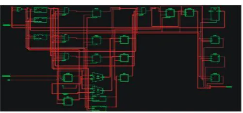
Fig. 1. RTL Schematic of Radix–2 Booth Multiplier
To represent detail of Second step perform in Algorithm is given in Fig. 2.
Fig. 2. Detail RTL Schematic of Second step
To represent detail of first Step perform in the Algorithm is given Fig. 3.
Fig. 3. Detail RTL Schematic of first step
IV. RADIX-4 ENCODER BOOTH MULTIPLIER
Radix-4 Booth algorithm which scan strings of three bits with the algorithm given below: (1) Extend the sign bit 1 position if necessary to ensure that n is even.
(2) Append a 0 to the right of the LSB of the multiplier.
(3) According to the value of each vector, each Partial Product will be 0, +y, –y, +2y or –2y. The negative values of y are made by taking the 2‘s complement.
The negative values of y are made by taking the 2‘s complement and Carry-look-ahead (CLA) fast adders are used. The
32 | P a g e
n/2 partial products are generated [10,11,12].To Booth recode the multiplier term, we consider the bits in blocks of three, such that each block overlaps the previous block by one bit. Grouping starts from the LSB, and the first block only uses two bits of the multiplier. Let us consider an example:
Multiplicand - (001011)
2
Multiplier - (010011)2
First of all we will make group of three bits for Multiplier
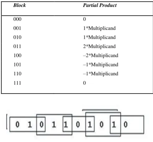
Encoding for Radix-4 Booth Multiplier will be done according to the table: 3.1 given below:
Table1: Encoding of Radix-4 Booth Multiplier.
Fig. 4. Grouping of bits for Multiplier
From the table 1.
(010)2 - 1 (001)2 - 1 (110)2 - (-1)
Therefore Multiplicand is multiplied with the three encoded digit which is 1, 1 and (–1).
(i) –1 * (001011)
2
= (001011)2
And 1111 added with the result because of negative sign. Thus final answer of multiplication of (-1) is (1111001011)2 {Negative term Sign Extended}
(ii) 1 * (001011)2 = (001011)2 (iii) 1 * (001011)2 = (001011)2
(iv) (00001)2 are added with these three resultants as an error correction for negation.
Block Partial Product
000 0
001 1*Multiplicand
010 1*Multiplicand
011 2*Multiplicand
100 –2*Multiplicand
101 –1*Multiplicand
110 –1*Multiplicand
33 | P a g e
1 1 1 1 1 1 0 1 0 0 Negative term sign extended 0 0 1 0 1 1
0 0 1 0 1 1
0 0 0 0 1 Error Correction for Negation
0 0 1 1 0 1 0 0 0 1 Discarding the carried high bit
A. Synthesis of Radix-4 Booth Multiplier
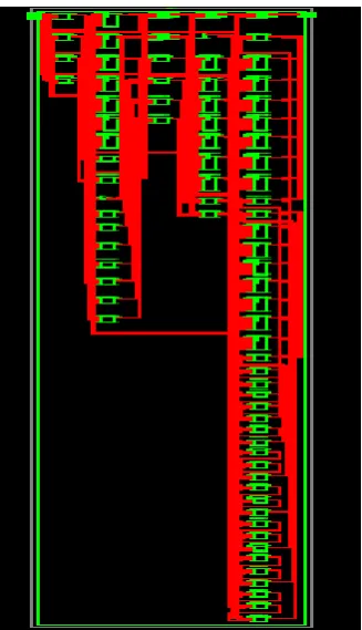
Fig. 5. RTL schematic of Radix-4 Encoder Multiplier.
34 | P a g e
Table2: Comparison of Radix-4 Booth with other Multiplier
Multipliers Logic
Delay (ns) Route Delay (ns) Total Delay (ns)
Shift and add multiplier 11.884 12.432 24.876 Wallace tree multiplier 14.364 8.141 22.847 Wallace tree multiplier
using compressors
13.580 8.131 21.711
Radix-2 booth multiplier 5.310 9.967 15.277 Radix-4 Booth multiplier 2.075 2.886 4.961
V. CONCLUSION
Radix-4 Booth Multiplier is implemented here; the complete process of the implementation is giving higher speed of operation. The two cycle of shifting process including addition and subtraction is available. Now at the same time RTL Schematic generated here is giving the comfortable execution of it. This RTL Schematic can be implemented in FPGA CPLD kit that will give the proper Output.
Now this RTL Schematic of Radix-2 Booth Multiplier is compared with implemented RTL Radix-4 Encoder Booth Multiplier. The Speed and Circuit Complexity is compared, Radix-4 Booth Multiplier is giving higher speed as compared to Radix-2 Booth Multiplier and Circuit Complexity is also less as compared to it. It is completely depend on the Algorithm used in both Multipliers.
REFRENCE
[1] A High-Speed Multiplication Algorithm Using Modified Partial Product Reduction Tree P. Asadee,
InternationalJournal of Electrical and Electronics Engineering, 4: 4,(2010).
[2] N. Jiang and D. Harris, ―Parallelized Radix-2 Scalable Montgomery Multiplier,‖ submitted to IFIP Intl. Conf. on VLSI, (2007).
[3] D. Kudeeth., ―Implementation of low-power multipliers‖, Journal of low-power electronics, vol. 2, 5-11, (2006).
[4] Y.N. Ching, ―Low-power high-speed multipliers‖, IEEETransactions on Computers, vol. 54, no. 3, pp. 355-361,2005.
[5] D. Harris, R. Krishnamurthy, M. Anders, S. Mathew, and S. Hsu, ―An improved unified scalable radix-2 Montgomery multiplier,‖ Proc. 17th IEEE Symp. Computer Arithmetic, pp. 172-178, 2005.
35 | P a g e
Conf. Signals, Systems, and Computers, pp. 1196-1200, Nov. (2005).
[7] J. Hensley, A. Lastra, and M. Singh. An area- and energy-efficient asynchronous booth multiplier for mobile devices. In Proc. Int. Conf. Computer Design (ICCD), (2004).
[8] A. Efthymiou, W. Suntiamorntut, J. Garside, and L. Brackenbury. An asynchronous, iterative implementation of the original Booth multiplication algorithm. In Proc. Int. Symp. On Advanced Research in Asynchronous Circuits and Systems, pages 207–215. IEEE Computer Society Press, Apr. (2004). [9] P. D. Chidgupkar and M. T. Karad, ―The Implementation of Vedic Algorithms in Digital Signal
Processing‖, Global J. of Engg. Edu, vol. 8, no. 2, pp. 153–158, (2004).
[10]M. Sheplie, ―High performance array multiplier‖, IEEE transactions on very large scale integration systems, vol. 12, no. 3, pp. 320-325, (2004).
[11]Design of a Novel Radix-4 Booth Multiplier, Hsin-Lei Lin, Robert C. Chang, Ming-Tsai ChanDepartment of Electrical Engineering, National Chung Hsing University, Taichung, TaiwanThe 2004 IEEE Asia-Pacific Conference on Circuits and Systems, December 6-9, (2004).
[12]Deepak Patidar, ― Efficient Architecture for Radix-2 booth multiplication using 4:2 compressor ‖ pp. 3529-3538, (2015)