R E S E A R C H
Open Access
Compressed sensing-based channel
estimation for ACO-OFDM visible light
communications in 5G systems
Muhammad Tabish Niaz
1, Fatima Imdad
1, Waleed Ejaz
2and Hyung Seok Kim
1*Abstract
In this paper, we propose a compressive sensing (CS)-based channel estimation technique for asymmetrically clipped optical-orthogonal frequency division multiplexing (ACO-OFDM) visible light communications (VLC) in 5G systems. We proposed a modified version of sparsity adaptive matching pursuit (SAMP) algorithm which is named as self-aware step size sparsity adaptive matching pursuit (SS-SAMP) algorithm. It utilizes the built-in features of SAMP and with additional ability to select step size according to the present situation, hence term self-aware, can provide better accuracy and low computational cost. It also does not require any prior knowledge of the sparsity of the signal which makes it self-sufficient. CS-based algorithms such as orthogonal matching pursuit (OMP), SAMP, and our proposed SS-SAMP were implemented on ACO-OFDM VLC. The paper is supported by simulation results which demonstrate performance of proposed scheme in terms of bit error rate (BER), mean square error (MSE), computational complexity, and key VLC parameter (LED nonlinearity, shot noise, thermal noise, channel response, and peak-to-average power ratio (PAPR). It is shown that the SS-SAMP is a good candidate for ACO-OFDM-based VLC that are mobile and have limited processing power, based on its performance and computational complexity.
Keywords:Bit-error-rate, Channel estimation, Compressed sensing, Visible light communication
1 Introduction
Visible light communication (VLC) is a promising optical wireless communication (OWC) technology which is paving its way to reality very quickly [1]. VLC uses LED emitted light which fulfills the dual functionality of illumin-ance and data transmission. VLC has shown potential to be an integral part of upcoming 5G networks. The market is continuously pushing the limits of the network data rate and capacity; it is very difficult for the wireless communica-tion industry to meet these demands. It is estimated that for 5G networks, there will be a 1000-fold increase in data traffic [2]. In order to meet these demands, 5G networks will have to rely on other more efficient technologies. It is highly likely that it will incorporate smaller cells (atto-cells), additional spectrum, energy efficient communication, and heterogeneous networks (HetNet) integration [3].
When compared to the traditional radio frequency (RF) wireless communication, VLC has many strong character-istics [4] such as the following:
Spectrum of visible light is free.
Light that cannot penetrate solid objects makes it secure for indoor transmission.
It can be deployed wherever LEDs are installed [5]. The signal-to-noise ratio (SNR) is usually high
because of high illumination requirements.
The fact that VLC can provide high bandwidth density can help in solving the demand of high bandwidth problem faced by upcoming RF-based networks. VLC can resolve supply and demand issue in 5G networks. Considering the positive traits of VLC at its present state can be best suited as a supplemental technology to assist HetNets in 5G networks. These main features of VLC make it a promising supplementary technology for 5G systems; however, it comes with various new challenges which open new re-search topics [6, 7].
* Correspondence:[email protected]
1Department of Information and Communication Engineering, Sejong University, Gwangjin-gu, Seoul, Republic of Korea
Full list of author information is available at the end of the article
Recently, optical orthogonal frequency division multi-plexing (OFDM) systems have gained a lot of popularity due to high bandwidth, power efficiency, flexibility, and use of license-free spectrum [8]. The optical OFDM works on the technique of intensity modulation and direct detection (IM/DD) [9]. There are many proposed methods utilizing the optical OFDM in VLC systems
[10–15]. In [11], Armstrong and Lowery have proposed
asymmetrically clipped optical OFDM (ACO-OFDM) which is a very efficient technique to be used with VLC system. Instead of sending all subcarriers, ACO-OFDM sends only odd subcarriers. ACO-OFDM has been shown to be more efficient in terms of optical power than the systems that use DC-biasing as it utilizes a large dynamic range of the LED. The ACO-OFDM technique performs well under interferences caused by inter-symbol interfer-ence (ISI) and inter-carrier interferinterfer-ence (ICI). It requires less optical power for a given data rate than other variants of optical OFDM if the constellation size is lower than 1024-QAM. In addition, ACO-OFDM is a good candidate for dimming systems because of its better performance at low-SNR regime. Due to these features, ACO-OFDM is used in this paper.
In VLC systems, due to interference from ambient light sources, estimating the channel for correct signal recovery is of utmost importance. Among studies on ACO-OFDM VLC systems, there have been proposals for channel esti-mation, which is an important part of wireless communi-cation systems. In [12], authors have proposed a technique to find channel state information (CSI) in the ACO-OFDM communication system for better channel estimation. A study has proposed a least square (LS)-based channel esti-mator to achieve highly accurate result in ACO-OFDM VLC systems [13]. Another study proposed the use of minimum mean square error (MMSE) and least minimum mean square error (LMMSE) based methods to improve the channel estimation of ACO-OFDM VLC systems [14, 15]. There is an alternate approach for channel es-timation, which utilizes the technique of compressed sensing (CS). The CS-based technique exploits the sig-nal sparsity and incoherency to achieve best results [16–20]. It relies on finding sparse solutions to under-determined linear systems and can estimate signals from fewer samples rather than using the Nyquist sam-pling rate [21]. The positive aspect of using CS technol-ogy is to have more accurate, fast ,and reliable channel estimation techniques, which are inexpensive and have low complexity.
2 Related work
The CS algorithms, which recover a sparse signal, are generally divided into two branches: linear programming (LP) and dynamic programming (DP). This paper focuses on the DP algorithm because most of the LP algorithms
tend to have high computational complexity. Due to the high complexity of LP algorithms, they do not perform well in real large-scale applications. The orthogonal matching pursuit (OMP) algorithm [22] is by far the most popular algorithm in DP category [23, 24]. The major drawback in DP algorithms is that they rely on the know-ledge of channel sparsity beforehand, which is not always possible in real practical applications. To counter the problem of channel sparsity information, sparsity adaptive matching pursuit (SAMP) was proposed in [25]. The SAMP algorithm uses an iterative method to estimate the signal sparsity, with a fixed step size to be used in each stage. This was an improvement over OMP algorithm, which usually requires the level of sparsity as a priori in-formation to estimate the original signal. The research in [25] showed that SAMP outperforms OMP and its vari-ants, but its drawback is that the MSE performance and complexity are directly related to the initial step size. Since mobile devices equipped with VLC modules have limited resources, the high computational complexity is a huge disadvantage.
There is no such literature that has worked on CS-based channel estimation in ACO-OFDM VLC systems. To the best of our knowledge, one article claims to improve the channel bandwidth of simple OFDM VLC system using CS [26]. The authors propose a new technique that can com-pensate the lack of channel bandwidth in an optical-OFDM link by using compressive sensing. The positive aspect of using CS technology is to have more accurate, fast, and reli-able channel estimation techniques that are inexpensive and have low complexity.
To summarize the current trend of research, most of the CS-based techniques are devised for RF-based chan-nel estimation. CS is very new in VLC domain, and there are very few literatures available which makes it a very open field for research.
3 Contribution
In this paper, a new self-aware step size SAMP (SS-SAMP) CS-based channel estimation algorithm is proposed for ACO-OFDM VLC system. The main contribution of our work is as follows:
SS-SAMP can adaptively adjust the step size. Due to the adaptive adjustment of step size,
convergence is faster.
SS-SAMP does not require a priori knowledge of
sparsity as in the case of other mentioned algorithms.
Section 5 presents simulation for the performance compari-son with existing CS-based channel estimation algorithms; finally, Section 6 concludes the paper.
4 System model
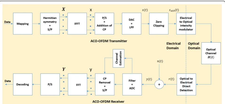
The block diagram of ACO-OFDM system is shown in Fig. 1. The system has three main parts: transmitter, chan-nel, and receiver. The transmitter is made up of OFDM modulator and optical modulator. The channel is assumed as a generic optical wireless channel. The receiver again is divided into two main parts: the optical demodulator and OFDM demodulator.
The main requirement of a VLC system to work is to have real and positive values from the optical modulator. This property usually employs the presence of IM/DD technique. ACO-OFDM also works on the IM/DD tech-nique and thus is simple to implement. The main problem here lies with the OFDM signal. Since they are complex and bipolar, simple OFDM system cannot be used with VLC system. It is necessary to make it unipolar and real. The ACO-OFDM modulator inherently does this work.
To ensure that the output of ACO-OFDM is real and unipolar, the following procedure is followed [14]. There areNsub-carriers out of which only odd ones will be used to send data. At the transmitter, the source bits are first modulated using Gray-coded M-ary quadrature amplitude modulation (QAM) mapping block. This will produce a complex bit stream. Then to maintain real OFDM symbols in time domain, the encoded data is passed through the Hermitian symmetry block. The data is then passed on to inverse fast Fourier transform (IFFT) block and clipping block so that the data is on odd subcarriers and positive.
Cyclic prefix (CP) is later added to avoid ISI. The addition of CP has a negligible impact on the SNR and spectral efficiency of the VLC system. To reduce the peak-to-average power ratio (PAPR), clipping is performed to combat two types of distortions: firstly the out-of-band distortion which is reduced by applying filtering and secondly the in-band distortion which is reduced by adding the CP. It is to be noted that in ACO-OFDM signal, only odd sub-carriers are sent [14]. The signal is converted from analog to digital using an analog-to-digital converter (ADC) and later, using optical inten-sity modulation (IM), the data is sent over the optical wireless channel.
There are two more types of interference noises, the narrowband interference (NBI) and impulse interference, which have to be taken into consideration. To solve these interferences, there are two methods that are com-monly used in ultra-wideband communication systems. One method is based on frequency domain and the other is based on time-domain schemes [27]. While keeping strictly within the scope of this paper, the fre-quency domain will be discussed. For frefre-quency-domain schemes, OFDM is used to combat these interference noises. One of the most prominent methods is the fre-quency threshold excision (FTE), in which the excess interference is clipped from the signal. The advantage of using ACO-OFDM is the intrinsic immunity to interfer-ences like NBI. It is shown in [11] that the interference component lies in the even sub-carriers while the odd sub-carrier’s components are affected by the multiplica-tion of a constant 0.5. ACO-OFDM also mitigates these interferences by clipping the signal before transmission.
This helps in containing the signal within the time frame hence minimize the interference. To further reduce the effects of these interferences, a narrowband optical
fil-ter can be used at the receiver [28–32]. CS has many
applications, one of these applications is of channel es-timation, which is discussed in this paper. One of the other applications of CS is the noise cancellation in which the sparsity is used to mitigate the effect of inter-ference noises including NBI and impulse noise. This discussion is out of the scope of this paper, since the scheme used in this paper strictly deals with the chan-nel estimation. The intrinsic immunity of ACO-OFDM towards the interference noise tries to minimize the ef-fect of these interferences.
At the receiver’s end, using direct detection (DD), the signal is received using photodiode (PD). This will con-vert the signal to digital electrical domain. The received signal is first recovered using different CS channel esti-mation techniques. The estimated signal is then passed to the ACO-OFDM demodulator block. After demodula-tion, the signal goes through the demapping block and original data stream is recovered.
The received signal at the receiver in time domain is represented as follows:
y tð Þ ¼ h tð Þxacoð Þ þt n tð Þ ð1Þ
In VLC, the channel h can be line-of-sight (LOS) and
non-line-of-sight (NLOS). The main property ofhis that it is always real and positive. The received signal in frequency domain can be expressed as
Y ¼HXaco þN ð2Þ
where Xaco is the ACO-OFDM signal, H is the OWC
channel response, and N is the noise. In this case, to make things simple additive white Gaussian noise (AWGN) is assumed. In optical channels, the quality of transmission is typically dominated by shot noise [33]. The desired signals contain a time-varying shot-noise process which has an average rate of 104to 105photons/ bit. Since in an office/home environment, there is ambient light striking the detector which leads to a steady shot noise having a rate of the order of 107to 108photons/bit, even if the receiver employs a narrowband optical filter. Therefore, in optical channels the ambient shot noise is modeled as a Gaussian process [34], hence AWGN channel is assumed. This is further discussed in detail inSection 4.1. Since VLC is considered to be an ultra-wideband (UWB) communication system [35], where the multipath com-ponents of the signal arrive at time intervals that are larger than the inverse of the bandwidth of the consid-ered channel. The sparsity depends on two aspects: the considered bandwidth (the larger the bandwidth the more likely the channel is sparse) and the considered
environment. Since VLC has a large bandwidth, the channel vector can be well approximated as a sparse signal [36–40]. Even if the desired channel vector is not sparse, the CS theory allows one to choose proper basis to express the signal as a linear combination of basis. Perfect synchronization between the transmitter and receiver is assumed.
Considering the two types of optical channel (i) LOS and (ii) NLOS, the expression of both types of channel can be found from Eqs. (3) and (4). The total diffused channel response can be computed by Eq. (6).
Hlosð Þ0
where Ar is the photodetector area,m1is the Lambert’s
mode number expressing directivity of the source beam,
Ts(ψ) is the receiver with optical bandpass filter, g(ψ) is the concentrator gain, ψ is the radiation incident angle,
ϕ is the angle with respect to transmitter, d is the distance of the transmitter, ΔA is the area of reflecting elements, kis the total number of reflector elements in the room, ρjis the reflection coefficient of j, and H
k−1 ð Þ nlos is the impulse response of order k−1 between the re-flector and receiver.
5 CS-based channel estimation method
In this section, the different channel estimation algorithms are discussed and the proposed scheme is given.
5.1 Least square channel estimation
5.2 OMP channel estimation algorithm
One of the earliest greedy iterative algorithm is orthogonal matching pursuits (OMP). It is one of the main stepping stones on which the other greedy algorithm is based on. The basic working of an OMP algorithm revolves under the conditions of a given iteration number. Since it is an iterative process, it is required to stop after certain iter-ations. To make accurate estimation of the original signal, OMP requires a lot of measurement data. One of the drawbacks of the OMP is that, as it requires a large number of measurement data to estimate the sig-nal, any increase in the degree of sparse or the number of samples would increase the time it takes to obtain the results. The basic working of OMP algorithm is shown in Algorithm 1.
5.3 SAMP channel estimation algorithm
The OMP algorithm is not adaptive. A pre-estimate of the sparse degree of the signal should be known and also the estimation accuracy is not so good. In an ac-tual scenario, the sparse degree is not known; hence, to make things easier and less complex the adaptive algo-rithm like sparsity adaptive matching pursuit (SAMP) was proposed in [24]. With this adaptive algorithm, the signal estimation does not require any information of signal sparse degree beforehand. The working of SAMP
requires to choose a step size s, which should satisfy
s≤K. The trade-off of choosing the step size is that if it is too small the algorithm will take long time to con-verge. Hence the choice of the step size is very import-ant in this algorithm. The SAMP algorithm has a high computational complexity and more computational time than OMP algorithm. The basic working of SAMP algorithm is shown in Algorithm 2.
5.4 SS-SAMP channel estimation algorithm
To specify the fine-tuning process, an additional threshold γ is specified. The proposed algorithm is shown in Algo-rithm 3. The algoAlgo-rithm is stagewise with a variable size of the final support set Fk in different stages. During each
stage,Fkadapts to two correlation test. These tests are the
candidate test and final test, which searched a certain num-ber of coordinates corresponding to the largest correlation values between the signal residual and the columns of the measurement matrix. In the next stage the algorithm runs until the recovered signal is found which has the least re-sidual. The SS-SAMP uses two threshold values for halting criterion. These two values are toleranceεandγ. The SS-SAMP algorithm comes to a halt when the residual’s norm is smaller thanε. On the other side, the values of the step size are decreased as the difference in energy of the esti-mated signal and original signal falls belowγ.
6 Discussion on different VLC characteristics In this section, different VLC characteristics are discussed such as LED nonlinearity, shot noise, and PAPR calculation. The effects of the proposed scheme on these parameters are discussed, and the results are shown in Section 5.
6.1 LED nonlinearity, shot noise, and thermal noise
Since this paper utilizes ACO-OFDM as the modulation scheme, one drawback is that the signal is limited due to the constraints imposed by the dynamic range of the LED. Due to the central limit theorem, the time domain signalx(k), depicts a Gaussian distribution for IFFT sizes larger thanN= 64 [41]. Therefore, according to [42], the average electrical symbol power is
Es¼2σ2x kð Þ ð7Þ
whereσ2
x tð Þis the variance of the signal.
Due to the directly proportional relationship between the radiated optical power and the forward current of the LED, the signal and constraints are described in terms of optical power. There are two main points on concern in the dynamic range imposed by the LED. One is the minimum optical power point, termed as PT x;min, and the other point is the maximum optical power point, termed as PTx;max. The point at which the optical
power bias is indicated is termed as PTx;bias. The signal
is clipped at the top level, to ensure the maximum power driving limit of the LED. The clipping at the top level can be expressed as top¼PTx;max−PTx;min. If the
LED is insufficiently forward biased, then it should be clipped at the bottom level, bottom¼PTx;min−PTx;bias,
this condition will only hold true if PTx;bias<PTx;min.
The signal after the conversion is then transmitted over the optical wireless channelh.
Since it is already mentioned that the optical power is directly proportional to the forward current in the LED, the relationship of the two variables is given below. In order to characterize the nonlinear distortion caused by the LED, the Bussgang theorem [41] is applied. The the-orem states that the nonlinear distortion can be modeled as an attenuation of the transmitted signal plus a distor-tion noise component, ηclip(k). The system is evaluated on the basis of the ratio between the power of the undis-torted part of the signal and the effective noise power, called effective SNR, which accounts for the contribu-tions caused by the clipping, shot noise, and thermal noise. The ratio is given as:
SNR¼ K
where α is the responsivity of the PD detector and
σ2
where q is the electronic charge, Ibg is the background light current,Bis the bandwidth,Pris the optical power received,T is the absolute temperature, RL is the load resistance, andkis the Boltzmann’s constant.
The analysis of the nonlinearity is done in Section 5.
6.2 PAPR
In this section the peak-to-average power ratio (PAPR) of the ACO-OFDM is discussed and the results will be analyzed in Section 5. The PAPR is defined as the max-imum power of the transmitted signal divided by the average power. The PAPR is given as:
PAPR¼ maxx
2ð Þk
E x½ 2ð Þk ð12Þ
Since in OFDM, there is a large number of sub-carriers, the system has a large dynamic signal range and exhibit a very high PAPR. Later when this OFDM signal is passed through the nonlinear LED, the signal degrades further and that effects the overall BER performance.
PAPR is usually presented in the form of CCDF. In this, we find the probability that PAPR value is higher than a certain PAPR value PAPR0, i.e., Pr(PAPR > PAPR0). The
simulation results are analyzed in Section 5.
7 Performance evaluation
In this section, the performance of different channel es-timation techniques is simulated and later the proposed scheme performance is analyzed on the basis of the key VLC parameters. The comparison of LS, OMP, SAMP, and proposed SS-SAMP are shown in two parameters, BER and MSE, since the main parameter that defines the accuracy of estimation signals is based on the step size. To simulate, three different step sizes are chosen: small, medium, and large step size. The MSE and BER are used to measure the channel estimation accuracy and the system performance, respectively. To measure the compu-tational complexity, CPU running time was computed. Simulations were performed in MATLAB R2015a using the i5 CPU with 4 GB of memory. The results were aver-aged using 1000 Monte-Carlo trials. Later, the proposed scheme is analyzed on how it will tackle the LED nonline-arity, shot noise, and thermal noise. Also, the channel response and the modulation constellation are analyzed to give a clear picture on how the proposed scheme will perform in an indoor VLC environment.
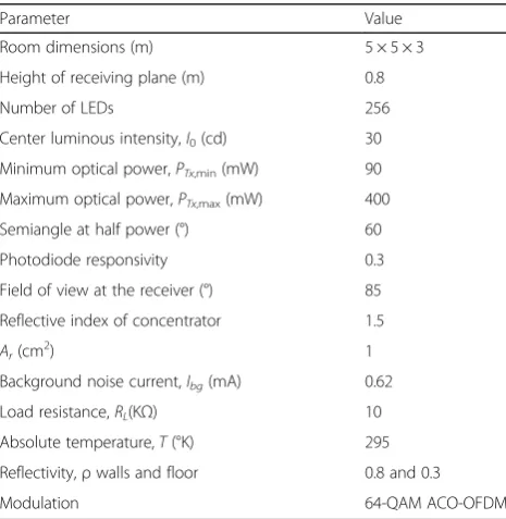
A simple VLC system model is implemented with ACO-OFDM. Simulation parameters are shown in Table 1. The optical wireless channel model used in this simulation is based on the work proposed by [43]. The calculation of ACO-OFDM BER with a M-QAM con-stellation is given as:
The calculation of MSE is done using the following Eq. (14):
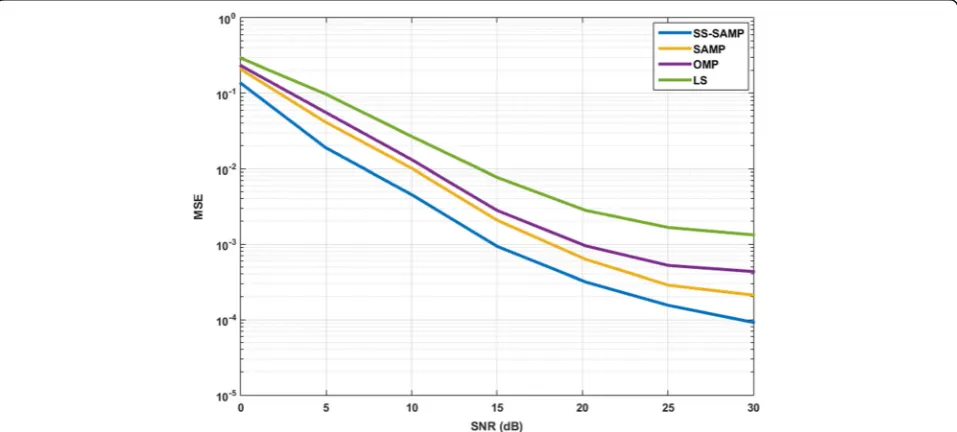
To evaluate the performance, BER was computed for all mentioned algorithms. Figure 2 shows that CS-based channel estimators perform better than the conventional LS-based estimator. It can be seen that the SS-SAMP performs better than SAMP. To further investigate the performance, the MSE is shown in Fig. 3. Again, the same trend can be seen as LS-based channel estimation algorithm performs poor with re-spect to the CS-based channel estimation algorithms. Since the step size is chosen according to the current status of the estimation signal, SS-SAMP outperforms SAMP and OMP.
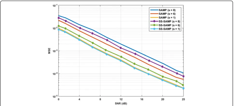
To further investigate the performance of SAMP and SS-SAMP with respect to the step size, Fig. 4 shows the
Table 1Simulation parameters
Parameter Value
Room dimensions (m) 5 × 5 × 3
Height of receiving plane (m) 0.8
Number of LEDs 256
Center luminous intensity,I0(cd) 30
Minimum optical power,PTx,min(mW) 90
Maximum optical power,PTx,max(mW) 400
Semiangle at half power (°) 60
Photodiode responsivity 0.3
Field of view at the receiver (°) 85
Reflective index of concentrator 1.5
Ar(cm
2
) 1
Background noise current,Ibg(mA) 0.62
Load resistance,RL(KΩ) 10
Absolute temperature,T(°K) 295
Reflectivity,ρwalls and floor 0.8 and 0.3
Modulation 64-QAM ACO-OFDM
performance of the two algorithms with three different initial step sizes. Earlier in Section 2, it was mentioned that the step size was chosen based on small, medium, and large values. These values are one for small, six for medium, and eight for large. Both algorithms are com-pared using these three step sizes, and Fig. 4 summa-rizes the results obtained. It can be seen that if small step size is chosen, the performance of both algorithms are the same. This is because, under this condition, both algorithms perform in the same way. But if we increase the step size to medium or large, SS-SAMP outperforms SAMP.
To conclude the performance analysis of the proposed SS-SAMP algorithm, running time of each CS-based channel estimation algorithm mentioned in this paper was computed to depict the computational complexity. All the algorithms were run on the same system with the same environment. Figure 5 shows the running time of these algorithms. From the results, it can be seen that OMP takes most of the time to run while SAMP, and SS-SAMP all give a respectable running time. It can be seen that as the SNR increases, both SAMP and SS-SAMP performances are comparable with a difference of approximately 0.002 s. Looking at all the results Fig. 2BER performance of different CS channel estimation algorithms
obtained, it can be said that the proposed SS-SAMP can be used in a mobile computational limited environ-ment with the computational complexity of slightly higher than SAMP.
As from the previous results, it can be seen that the proposed SS-SAMP is a good candidate for a mobile computational limited environment. It is also required to analyze the performance under different VLC system key parameters. Earlier in Section 4, the key parameters of VLC system were discussed and now the performance analysis is given. To start with the analysis, the key simulation parameters are the same as mentioned in
Table 1. The first sets of parameter that will be analyzed are the LED nonlinearity and the effect of the shot noise and thermal noise on the VLC system. To investigate the output characteristics of a practical LED, an LED transfer function is modeled through a polynomial using the least-square curve fitting technique. An OPTEK white LED is considered in this simulation. For this type of LED, the forward current varies from 100 mA to 1 A and the out-put optical power lies between 90 mW to 400 mW. Since according to the European lighting standard [44], the illuminance for home/office environments is 400 lx. To check the LED nonlinearity, Fig. 6 shows the achievable Fig. 4MSE calculation of SAMP and SS-SAMP with different step sizes
brightness in percentage of a function of transmitted op-tical power of the given LED light. For this analysis, it is assumed that the dimming level is 0% and, to achieve the European lighting standard, the LED should operate at a minimum 35% brightness level. To operate at this level, Fig. 6 depicts the recommended bias point of operation that is (350 mA/180 mW).
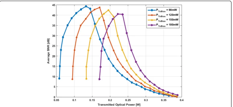
The performance of the system is assessed in terms of average SNR at the receiver. The SNR values obtained were simulated against the transmitted optical power of both ideal and practical LED. Figure 7 shows the SNR of a practical LED operated at different biasing values,
while Fig. 8 shows the performance of an ideal LED under the same biasing values. It is assumed that the modulation bandwidth is of 20 MHz. On observation, it can be seen that the system performance improves as the optical power is increased. At the recommended biasing point, the system shows the best performance. If the optical power is increased beyond this point the sys-tem performance starts to deteriorate. This is due to the nonlinearity distortion induced by the dynamic range of the LED. At this point, the signal clipping is more highlighted and the clipping noise becomes significant. One major point to note is that by setting the proper Fig. 6Transmitted optical power vs. brightness of LED
biasing point, the best SNR can be achieved for the VLC system. As an example, if the system wants to operate at 35% brightness to maintain 400 lx, the best SNR value is 44 dB which is achieved if the biasing power is set to 120 mW and the optical signal power is 60 mW. For the same brightness but at a lower SNR of 38 dB, the biasing power should be 150 mW and the optical power at 30 mW. Multiple configuration can be obtained depend-ing on what SNR is required for the VLC system to op-erate efficiently. One thing to note is that whatever the biasing power and optical power is selected, the resulted optical transmitted power will always be 180 mW in this
specific case. Since this simulation only deals with the minimum illumination requirements, other possible op-erating range can be determined by the method and relevant SNR can be computed.
The channel response of the diffused environment which includes both LOS and NLOS signals can be seen in Fig. 9. The channel gain is given in Eq. (6), and the optical wireless channel model is already men-tioned at the start of this section. From the figure, it can be clearly seen that the main LOS component and the additional reflected NLOS components and their relevant reflection count.
Fig. 8Average SNR of an ideal LED
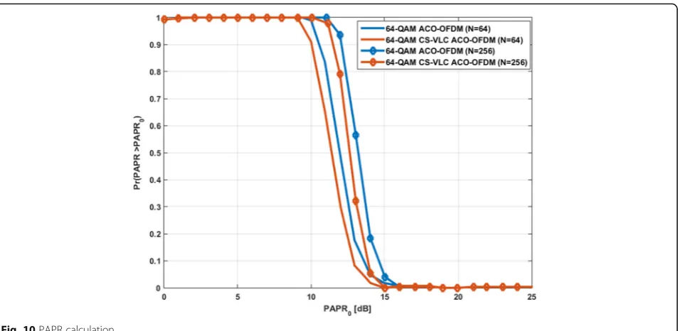
The next variable to investigate is the PAPR of the proposed VLC system. The PAPR calculation again follow the same simulation parameters with the results averaging of 1000 Monte-Carlo simulations. The
car-rier sizeNis changed fromN= 64 toN= 256, and the
comparison is made based on the performance. Also, PAPR of a simple ACO-OFDM VLC system is com-pared with the proposed CS ACO-OFDM VLC system. There is a slight improvement of using the CS-based methods because CS exploits the sparsity of the signal. Since in ACO-OFDM, only odd sub-carriers are sent and then applying CS techniques, the data size is fur-ther reduced and that can help improve the PAPR of the system. Figure 10 shows the CCDF of the PAPR for both normal ACO-OFDM VLC and CS-based ACO-OFDM VLC. It can be seen that the PAPR is slightly improved but as the number of sub-carriers are increased from 64 to 256 the PAPR is increased.
Since ACO-OFDM performs better with lower modu-lation levels and less sub-carriers, it is safe to use CS-based techniques for limited computational mobile based application.
The constellation diagrams of a simple ACO-OFDM and proposed CS-based ACO-OFDM system are ana-lyzed next. Figure 11 shows the constellation diagram of both implementation side by side. Figure 11a shows the constellation diagram of a 64-QAM ACO-OFDM while Fig. 11b shows the constellation diagram of a 64-QAM CS-based ACO-OFDM. The constellation diagram of Fig. 11a is fuzzy as it is degraded by the effect of chan-nel, and the BER performance is degraded as there is interference among different constellation points. As CS-based channel estimation techniques are used, the overall constellation is improved and every constellation point can be identified easily. This will also improve the BER performance of the VLC system.
Fig. 10PAPR calculation
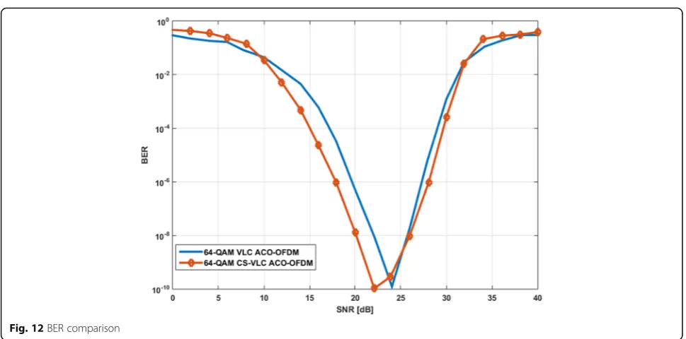
To conclude the analysis of VLC system key parameters, the last parameter to look into is of BER performance. Figure 12 shows the overall performance of both simple ACO-OFDM and proposed CS-based ACO-OFDM sys-tems. It can be seen that the CS-based ACO-OFDM performs better. The important thing to mention here is the effect of the LED nonlinearity. If the biasing point is not chosen carefully, the system performance will degrade drastically. Figure 12 is based on the values chosen in the previous mentioned analysis.
8 Conclusions
In this paper, a new modified CS-based channel estima-tion algorithm SS-SAMP was proposed for the ACO-OFDM VLC system. The performance was evaluated in terms of BER, MSE, computational complexity, and key parameters of VLC system (nonlinearity, noise, channel response). The results show that CS-based techniques: OMP, SAMP, and SS-SAMP perform better than the traditional LS-based method. SS-SAMP stood out to be the best among the algorithms applied to the VLC-based system. The OMP algorithm requires the knowledge of sparsity beforehand. The SAMP algorithm is an im-proved adaptive version of OMP, but the computational cost is on the higher side due to the fact that the SAMP algorithm has to start with a random step size. It is shown through the performance analysis that SS-SAMP can improve the channel estimation accuracy without significantly increasing the computational complexity. It can be said that CS-technology-based algorithms can be used with the ACO-OFDM VLC system and can give accurate estimation of the original signal and still can manage to have an acceptable computation time.
Acknowledgements
This work was supported by the National Research Foundation of Korea (NRF) grant funded by the Korea government (No. 2016R1A2B4008457) and by the Strengthening R & D Capability Program of Sejong University.
Authors’contributions
The research presented in this paper was a collaborative effort among all authors. MTN conceived, implemented and simulated the results along with the paper writeup. FI and WE wrote the paper and discussed the results. HSK revised the manuscript critically. All authors read and approved the final manuscript.
Competing interests
The authors declare that they have no competing interests.
Author details
1Department of Information and Communication Engineering, Sejong University, Gwangjin-gu, Seoul, Republic of Korea.2Department of Electrical and Computer Engineering, Ryerson University, Toronto, Ontario, Canada.
Received: 29 April 2016 Accepted: 14 November 2016
References
1. Z Ghassemlooy, W Popoola, S Rajbhandari, Optical wireless communications: system and channel modelling with MATLAB®. (CRC Press, 2012)
2. Qualcomm incorporated: the Qualcomm 1000x challenge (2013), HYPERLINK“https://www.qualcomm.com/invention/1000x”https://www. qualcomm.com/invention/1000x. Accessed 24 Apr 2016
3. MB Rahaim, L TDC, Towards practical integration of dual-use VLC within 5G networks. IEEE Wirel Commun.22, 97–103 (2015)
4. L Garber, Turning on the lights for wireless communications. Computer
44, 11–14 (2011)
5. H Elgala, R Mesleh, H Hass, Indoor optical wireless communication: potential and state-of-the-art. IEEE Commun. Mag.49, 56–62 (2011)
6. DC O’Brien, L Zeng, H Le-Minh, G Faulkner, JW Walewski, S Randel, In IEEE 19th International Symposium on Personal, Indoor and Mobile Radio Communications, 2008. PIMRC 2008. Visible light communications: Challenges and possibilities, (2008), pp. 1–5.
7. J Armstrong, RJ Green, MD Higgins, Comparison of three receiver designs for optical wireless communications using white LEDs. IEEE Commun Lett
8. J Armstrong, OFDM for optical communications. J Light Technol27, 189–204 (2009)
9. SD Dissanayake, J Armstrong, Comparison of ACO-OFDM, DCO-OFDM and ADO-OFDM in IM/DD systems. J Light Technol31, 1063–1072 (2013) 10. JM Kahn, JR Barry, , Wireless infrared communications. Proc IEEE85,
265–298 (1997)
11. J Armstrong, AJ Lowery, Power efficient optical OFDM. Electron Lett42, 370–372 (2006)
12. P Errong, C Fang, L Jibi, Optimal power allocation for OFDM-based cognitive radio systems with fair protection against primary users. J Comput Inf Syst8, 9831–9837 (2012)
13. D Wu, Z Wang, R Wang, J He, Q Zuo, H Zhao, Channel estimation for asymmetrically clipped optical orthogonal frequency division multiplexing optical wireless communications. IET Commun6, 532–540 (2012) 14. H Zhao, M Li, R Wang, D Wu, Channel estimation for asymmetrically clipped
optical orthogonal frequency division multiplexing communication system. Opt Eng52, 076111 (2013)
15. S Qaisar, RM Bilal, W Iqbal, M Naureen, S Lee, Compressive sensing: from theory to applications, a survey. J Commun Netw15, 443–456 (2013) 16. EJ Candes, MB Wakin, An introduction to compressive sampling. IEEE Signal
Proc Mag25, 21–30 (2008)
17. S Ji, Y Xue, L Carin, Bayesian compressive sensing. IEEE Trans Signal Proc
56, 2346–2356 (2008)
18. EJ Candes, J Romberg, Sparsity and incoherence in compressive sampling. Inverse Probl23, 969 (2007)
19. EJ Candes, The restricted isometry property and its implications for compressed sensing. C. R. Math346, 589–592 (2008)
20. EJ Candes, J Romberg, T Tao, Robust uncertainty principles: exact signal reconstruction from highly incomplete frequency information. IEEE Trans Inf Theory52, 489–509 (2006)
21. YY Won, SM Yoon, Compressive sensing-based channel bandwidth improvement in optical wireless orthogonal frequency division multiplexing link using visible light emitting diode. Optics Express22, 19990 (2014) 22. J Tropp, A Gilbert, Signal recovery from random measurment via orthogonal
matching pursuit. IEEE Trans Inf Theory53, 4655–4666 (2007)
23. C Berger, S Zhou, J Preisig, P Willett, Sparse channel estimation for multicarrier underwater acoustic communication: from subspace methods to compressed sensing. IEEE Trans Signal Proc58, 1708–1721 (2010)
24. C Berger, Z Wang, J Huang, S Zhou, Aplication of compressive sensing to sparse channel estimation. IEEE Commun Mag48, 164–174 (2010) 25. T Do, NNG Lu, T Tran,Proceedings of the 42nd Asilomar Conference on Signals,
Systems and Computer(Sparsity adaptive matching pursuit algorithm for practical compressed sensing, Pacific Grove, CA, 2008), pp. 581–587 26. CN Reinhardt, S Jaruwatanadilok, Y Kuga, A Ishimaru, JA Ritcey, Investigation
of multilevel amplitude modulation for a dual-wavelength free-space optical communications system using realistic channel estimation and minimum mean-squared-error linear equalization. Appl. Opt47, 5378–5389 (2008) 27. S Liu, F Yang, J Song, Narrowband interference cancelation based on
priori aided compressive sensing for DTMB systems. IEEE Trans Broadcast
61(1), 66–74 (2015)
28. AJC Moreira, RT Valadas, AM Oliveira Duarte, IET Conference Proceedings, Reducing the Effects of Artificial Light Interference in Wireless Infrared Transmission Systems, 1996, p. 5
29. RP Jimenez, J Rabadan, FL Hernandez, Filtered modulation schemes for short distance infrared wireless communications. IEEE Trans Consum Electron46(2), 275–282 (2000)
30. F Delgado, RP Jiménez, J Rabadán, FL Hernández, Design of fast frequency-hopping spread-spectrum system for wireless infrared communications. Electron Lett36(17), 1510 (2000)
31. J Rabadan, M Bacallado, F Delgado, S Perez, RP Jimenez, Experimental characterization of a direct-sequence spread-spectrum optical wireless system based on pulse-conformation techniques for in-house communications. IEEE Trans Consum Electron50(2), 484–490 (2004) 32. O Gonzalez, RP Jimenez, S Rodriguez, J Rabadan, A Ayala, OFDM over
indoor wireless optical channel. IEE Proc - Optoelectron152(4), 199 (2005) 33. J Barry,Wireless Infrared Communications(Kluwer Academic, Boston, MA, (2004) 34. R Gagliardi, S Karp,Optical Communications(Wiley, New York, 1984) 35. M Wang, J Wu, W Yu, H Wang, J Li, J Shi, C Luo, Efficient coding modulation
and seamless rate adaptation for visible light communications. IEEE Wirel Commun22(2), 86–93 (2015)
36. C Berger, Z Shengli, J Preisig, P Willett, Sparse channel estimation for multicarrier underwater acoustic communication: from subspace methods to compressed sensing. IEEE Trans Signal Proc58(3), 1708–1721 (2010) 37. W Li, J Preisig, Estimation of rapidly time-varying sparse channels. IEEE J
Ocean Eng32(4), 927–939 (2007)
38. W Bajwa, J Haupt, A Sayeed, R Nowak, Compressed channel sensing: a new approach to estimating sparse multipath channels. Proc IEEE98(6), 1058–1076 (2010)
39. S Cotter, B Rao, Sparse channel estimation via matching pursuit with application to equalization. IEEE Trans Commun50(3), 374–377 (2002) 40. R Prasad, C Murthy, B Rao, Joint approximately sparse channel estimation
and data detection in OFDM systems using sparse Bayesian learning. IEEE Trans Signal Proc62(14), 3591–3603 (2014)
41. H Elgala, R Mesleh, H Haas, Indoor broadcasting via white LEDs and OFDM. IEEE Trans Consum Electron55, 1127–1134 (2009)
42. O Gonzalez, RP Jimenez, A Ayala, OFDM over indoor wireless optical channel. IEE Proc - Optoelectron152, 199–204 (2005)
43. L Weihao, Z Difan, X Zhengyuan, Modelling of optical wireless scattering communication channels over broad spectra. J Opt Soc Am A32, 486–490 (2015)
44. European Standard EN 12464-1,Lighting of indoor Work Places, 2009
Submit your manuscript to a
journal and benefi t from:
7Convenient online submission
7Rigorous peer review
7Immediate publication on acceptance
7Open access: articles freely available online
7High visibility within the fi eld
7Retaining the copyright to your article