Survey on Camera Tampering Detection in Real Time
Using Two Stage Scene Matching
Mr. Deepak V & Prof. Rakesh V. S
1
8
thSemester Student, Cambridge institution of technology, Bangalore, Karnataka, India.
E-mail: [email protected]
2
Professor, Cambridge institute of technology, Bangalore, Karnataka, India.
E-mail: [email protected]
Abstract
This survey describes a novel technique for camera tampering detection. It is implemented in real-time and was developed for use in surveillance and security applications. Cameras installed in many places are exposed to sabotage or tampering. The algorithm is based on background modelling, histograms comparison, edges comparison and analysis of the image’s average brightness.
In the first stage, we use the intensity of edges as the main cue to detect the camera tampering events. Instead of using the entire edge points of the images, we sample the most significant edge points to represent the scene. Whenever the first stage detects the tampering event, the second stage is triggered to reduce false alarms. In the second stage, we propose an illumination change detector which can check the consistency of the scene structure using cell-based matching method. The experimental results demonstrate that our system can detect the camera tampering precisely and minimize false
alarm even when the illumination changes
dramatically or large crowds passing through the scene. The performance of this method is
shown to be extremely favorable in real-world settings.
Keywords: Image Processing, Tampering Detection, Traffic Surveillance.
1.
Introduction
There are a large number of cameras installed in places such as company, hotel, and train station for security purpose. When a crime event occurs, criminals might destroy the camera to prevent their suspicious activities being captured. A reliable video is perquisite for all the technologies of intelligence video surveillance. Camera tampering can be defined as deliberate man-made actions which result in camera view changed and useless video. Therefore, it becomes critical to protect the cameras from tampering. Camera tampering detection is a fundamental problem, but only few literatures are proposed to detect camera tampering event.
Detection of camera tampering is an important problem in such situations. If the tampering is intentional, it could be indicative of a more profound suspicious activity to which security personnel should be alerted. If unintentional, the tampering should still be noted since it may reduce the surveillance capabilities of the camera. Detecting camera tampering can be a deceptively easy problem. First, the exact definition of what constitutes camera tampering must be established. For this work, camera tampering is defined as any sustained event which dramatically alters the image seen by the camera. Some examples of camera tampering are a person holding his/her hand in front of the camera, spray painting the lens, or turning the camera so that it points in a different direction. Such an event must be sustained for several seconds in order to be detected. The camera location is an important consideration since there may be events that are harmless and expected but still cause large changes in the image, and these should be distinguished from real tampering events. For example, for cameras mounted in a train station, the system should be insensitive to the motion of trains and large crowds of people in the scene. The approach used here can be summarized as follows. First, incoming frames of video are stored in buffers. The computation is done in two major stages:
1. Recent frames of video are compared to older frames using several measures of image dissimilarity.
2. Based on these measures, a set of rules is evaluated to decide if camera tampering has occurred.
Second type of camera tampering detection is an important issue must be solved, but few literatures address this issue in depth. FPGA devices can be part of an advanced video surveillance systems. The literature contains a number of implementations of algorithms useful in this type of application such as background modelling determining the optical flow tracking , pedestrian detection etc. The FPGA can be a hardware accelerator, working with a PC, in particular a ”reconfigurable frame grabber,” which captures the image directly from the camera and after the initial analysis, transfers it to the PC.
2.Existing Tampering Detection Methods
Defocus detection
In this type of sabotage the settings for the camera lens are changed or a semi-transparent material is placed in front of the lens. As a results the registered video frames are blurred. Similar effects may also be caused by natural phenomena such as rain or fog. Defocusing detection is usually based on an analysis of the image gradient. An important feature is the calculation of the coefficient only for ”stable” edges (edges present on the scene for a long time, presumably belonging to stationary objects). An approach based on transforming the image of the current frame and the background model into Fourier space was presented in work . Furthermore, in order to improve the reliability, an adaptive thresholding method and narrowing the analysis to areas (blocks of size 8x8 pixels) with no movement were introduced.
Occlusion detection
In this event the camera lens is covered partially or totally,including over painting, so that registering some part or the whole scene is impossible. One of the approaches to the occlusion detection is the analysis of the image entropy. It is carried out for parts of the image (particularly important are the areas where it is assumed that no moving object is able to obscure the field of
view). It was assumed that an occlusion will result in a large homogeneous area, which will be reflected in the histogram in the form of a larger maximum value for the current frame. In addition, analysis of the difference between the histograms was performed.
Displacement detection
In this event the camera field of view is altered. In can be done by rapidly or slowly moving the whole camera. As a result a part of the scene is not
surveilled. Most of the displacement detection methods are based on correlation calculation between the current frame and a reference model
a similar approach based on the calculation of zero-mean normalized cross-correlation (ZNCC) between the current frame, and the previous one, but only for pixels considered as background was used edge images (sub-bands after DWT transform) of the current scene and the background model were compared to detect displacement. a different approach was presented in the work . The displacement is detected by comparing current and historical background.
Other approaches
All of the methods mentioned above use a intensity or edge background model. Another approach was presented in the work , where it was decided to describe the image by using
two indicators: edge energy and standard deviation. Both were determined for the whole image, as well as for image patches. The main disadvantage of this approach is the need to compare each image from the short-term buffer, with each of the frames in the long-term buffer. Implementation of this type of algorithm in a pipelined image processing system is not straightforward and very resource consuming.
3.System Architecture
monitored. When a lot of sample points are unreliable, the system will resample the points. During the re-sampling, the camera tampering detection process would still work The Proposed Method simultaneously. Once any event detected in the first stage, the second stage detector will be triggered. Generally, the abrupt change of illumination will render camera tampering event in the first stag. We propose an illumination change detector in second stage to reduce false alarm. The illumination detector is able to screen out false alarms by comparing the structure of the images before and after lighting change such as lights are on/off.
4.Proposed Method
Based on the analysis of the camera tamper detection methods described in the literature a own method was implemented in C++ using the OpenCV library , which also constitutes a reference model for the hardware implementation. It is most similar to the solution described in the work , but differs in some details and was adapted for implementation in FPGA. The proposed camera tampering detection method is based on three mechanisms:
histograms comparison between short and long-term background model,
edge comparison between current frame and short-term background model,
mean brightness analysis.
The basis of the method are two background models in grey scale: the short and long-term one and the mechanism of calculating the absolute difference between two adjacent frames. The background model is updated using the moving average approach , which is described by equation:
where: I - current frame from the video sequence, B – background model, _ - background update rate. The background is updated only for stationary pixels. The movement mask is determined on the basis of thresholded absolute difference of two consecutive frames. The short-term model is updated with the current frame and the long-term model is updated with the short-term model.
At the outset, it was assumed that parts of the image where movement was detected should be excluded from analysis.
Therefore, the motion history image (MHI) is used. It was generated on the basis of foreground object mask obtained by thresholding the absolute difference between the current frame and the
short-term background model. The MHI image is updated according to:
where: MHI(x; y) motion history image for an image location, a and b MHI update parameters, _BGQ – absolute difference between current frame and short-term background model, the Background - background subtraction threshold, _F - absolute difference of two consecutive frames, the Movement consecutive frame differencing threshold. The pixels for which MHI value does not exceed a certain threshold are considered as stationary. Because of the hardware implementation the MHI values are limited to the range.
Histogram comparison
In the first stage for the short and long-term background model 32 bins histograms are calculated. Only stationary pixel are accumulated in the histogram.
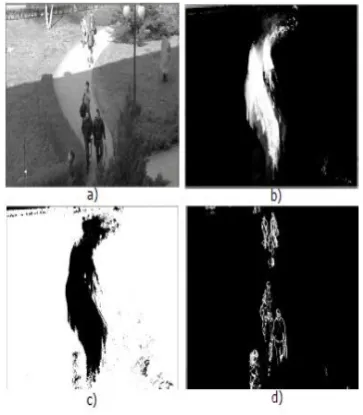
Figure 1.Sample MHI image a)current frame b)MHI image c)Thresholded MHI image d)Thresholded consecutive frame differencing.
chi-square, intersect, Bhattaharayya and a simplification of the correlation ratio described by the formula:
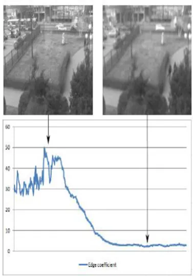
Figure 2. Histogram comparision example on partial camera field of view
Occlusion Event
Edge comparison
The Sobel gradient operator (vertical and horizontal) is used to detect edges. In the next step, the magnitude is computed (as a sum of absolute differences) for current image and short-term background model. It was assumed that only the edges belonging to the stationary part of the scene are analysed (based on the thresholded MHI). Also the magnitude difference between the current scene and the short term background model must exceed a threshold (only the strong edges are analysed). For such localisations the computed measure is defined as:
where: Ga - magnitude for the current image, Gb magnitude for the short-term background model. The used edge measure for a defocusing tampering situation is presented.
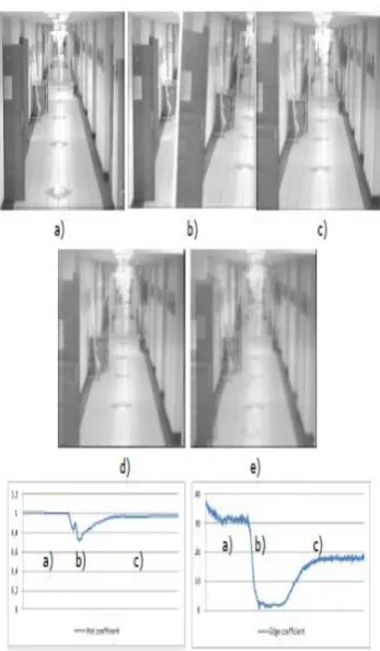
Figure 3. Edge comparision example on camera defocusing event.
Mean lightness analysis
In order to detect rapid lighting condition changes – brightening or dimming the analysed image, the mean lightness (for stationary areas) is computed. The value is then filtered by an moving average (equation similar to (1). In the next step, the value from the current frame is compared to the one K frames before (FIFO buffer). If the computed difference is above the threshold, the rapid light change event alarm is reported. An example is presented.
Figure 4. False photo tampering event. a) frame before tampering, b) frame during inserting the photograph, c) frame after tampering d) short-term background model e) long-short-term background model
5. Conclusion
We have presented a technique for detection of camera tampering that can be implemented in real-time. The algorithm is based on the information from background generation, consecutive frames difference, motion history image generation and several measures computation: histogram differences between short and long-term background models,
edge measure and mean lightness analysis. The final system was integrated and tested on the ML605 Xilinx evaluation board with the Virtex 6 FPGA device. It is able to process the video stream of resolution 640x480@60 fps in real time. The presented solution can be used as a part of advanced video surveillance system either as an accelerator in PC or embedded into a smart camera.
6. References
[1]E. Ribnick, S. Atev, O. Masoud, N. Papanikolopoulos and R. Voyles, “Real-Time Detection of Camera Tampering”, IEEE conference on advance video and signal based surveillance, Sydney, 2006.
[2]T. Kryjak, M. Komoekiewiez and M. Gorgon, “FPGA IMPLEMENTATION OF CAMERA TAMPER DETECTION IN REAL-TIME” IEEE conference on design and Architecture for Signal and image processing,Karlsruhe,oct.2012.