Implementation of FPGA for Automatic
Reverse Braking System
Divya Thakur1, Dr. Ajay P. Thakare2
M.E Student, Department of Electronics & Telecommunication Engineering, Sipna, C.O.E.T, Amravati, India1 Professor & H.O.D, Department of Electronics & Telecommunication Engineering, Sipna, C.O.E.T, Amravati, India2
ABSTRACT: Automation technology have provided us with various systems that reduces the time and human error. Vehicles, particularly four wheelers are very difficult to drive in the reverse direction. As personally one is very careful about, otherwise damage being caused to the vehicle. In view of this to provide a proper guidance to the vehicle in reverse direction, means are provided. Presently the vehicle has alarm system for maintaining the safe distance between vehicle and object while moving in reverse direction. When the vehicle gets too close to the object, the alarm is triggered this warns the driver about an object. But this feature has many problems and is prone to human error. We h ave en han ced th e facility by usin g automatic br akin g when an obstacle is close by. Therefore, in this paper we propose an “Automatic Reverse Braking system” to prevent collision by using sensors to detect obstacles. The “Automatic Reverse Braking system” will process the sensor data and control the vehicle to prevent accidents caused by careless driving or difficulty in detecting objects in reverse path. In this controlling logic is implemented on FPGA using Xilinx software. The system designed by VHDL keeps a distance between the object and vehicle to prevent accidents.
KEYWORDS:FPGA, Control unit, sensors, Automatic braking, sensing circuit. I. INTRODUCTION
An automobile has been used to move human beings or as a carriers since the automobile was invented. Recently, the automobile is thought as daily necessasity because we spend much time with automobiles, such as we require it for emergency services, in factories, to carry loads etc. The use of electronic components in automobiles is set to accelerate and with ongoing efforts to improve safety and comfort, many approaches such as antilock brake systems, traction control systems, and electronic stability programs have been invented to achieve success in collision avoidance. The goal of vehicle safety ultimately is that a vehicle by no means collides, but it induces a large number of problems that we must solve. Collision, particularly for reversing collision due to careless or violent driving, is the most important major cause that leads to traffic accidents. Fig.1 shows how difficult it is to drive in reverse direction. Unfortunately, because a human driver is never perfect, some minor mistakes by the driver may result in a great deal of losses when the vehicle’s driver reverses.
According to the National Highway Traffic Safety Administration, 8% of the accidents occur during driving in reverse [4]. In traffic safety, obstacle detection and recognition play an important role in preventing reversing collision. The earlier an obstacle of a potential reversing collision is detected, the more chances there are available to protect passengers and other road users. Researches have been made on automatic braking systems, but we are introducing automatic brakes in reverse path.Therefore in this paper we propose a system which will help in enhancing the performance of vehicles moving in reverse and thus contributing to the upcoming automobiles technology.
This system includes a novel technology to make vehicles safer and more efficient. The system is probably the most reliable means of detecting human beings and objects and, therefore, invaluable in the prevention of injury or fatal accidents. The aim of this paper is to develop an automatic braking system Our aim is to design the “Automatic Reverse Braking System” when the vehicle detects an obstacle in its reverse path using FPGA( Field Programmable Gate Array)which can avoid the accident in reversing the heavy loaded vehicles like trucks, buses and all the vehicles consisting of braking system.. If there is object in reverse path, the sensor senses the object and the break is applied automatically. In this, FPGA is used as a control unit to which the devices and sensors are interfaced. This system is suitable for commercial vehicles such as car, emergency services vehicles, trucks and buses.
II. LITERATUREREVIEW
There have been considerable advances in modern vehicle braking systems in recent years. In automation field , designers have proposed several enhancements. A precise short range radar system[1] was developed for anti-collision applications where automatic braking is applied in response to detection of a collision risk where a very high probability of detection is accompanied by a very low level of false alarms. A brake strategy for an automatic parking system [2] of vehicle has proposed brake controller which work with the automatic parking system and make the
process of parking smooth and stable. Autonomous antilock braking system (ABS) system [3] which can take over the
traction control of the vehicle is developed for a four wheel vehicle. ABS is a braking system that maintains control over the directional stability of the vehicle during emergency braking or braking on slippery roads by preventing wheel lock-up. Auto-Braking System using Sensor [4] was proposed to prevent front-end, rear-end, right-turn and left-turn accidents on roads. This module can detect the distance between front vehicle and driver’s vehicle to keep a constant distance using a sensor and operate the brake system.
All the above proposed design models contributed to safety of vehicles and pedestrians. It prevented rear end crashes, provided ABS for sharp turns or slippery roads. But all these are applicable for vehicles running in conventional direction, so we need to develop systems which enhances the performance and safety of vehicles when it moves in reverse direction. A model designed [8] on reversing of vehicles provided detection of obstacle , speed control mechanism based on binocular cameras. The system [9] uses various sensors to reduce the major cause of vehicle reversing collision but drivers overlooks the vital information of rear obstacles.Thus, in this paper we propose an “Automatic Reverse Braking system” to prevent collision by using sensors to detect obstacles. The “Automatic Reverse Braking system” is processing the sensor data and controlling the vehicle to prevent accidents.
III.PROPOSED WORK
Fig.2. Block Diagram
The IR (Infrared) sensors are used as obstacle sensors in our system which is operated all the time while reversing the vehicle. The IR sensors consists of IR Transmitter and Receiver as shown in Fig.3
Fig.3: IR(Infrared) Transmitter and Receiver Fig.4: Schematic Diagram of Sensing circuit
Here as shown in fig.3 ,the object can be anything which has certain shape and size, the IR LED transmits the IR signal on to the object and the signal is reflected back from the surface of the object. The reflected signals is received by an IR receiver.
Fig.4 shows the schematic of sensing circuit. In our system, Sensing circuit consists 555 IC which is used as astable multivibrator.The frequency of the 555 is tuned using the potentiometer as shown in fig.4.The output of 555 is given to the IR transmitter. TSOP detects a frequency of 38 KHz. The output of TSOP goes low when it receives this frequency. Hence the output pin is normally high because, though their LED is continuously transmitting, due to no obstacle, nothing is reflected back to the TSOP. The indication LED is off. When an obstacle is encountered, the output of TSOP goes low, as the required frequency is reflected from the obstacle surface
.
The processing part in our system is FPGA (Field Programmable Gate Array) as a controller to which the sensors are interfaced. FPGA accepts the signal from sensors and process the signals and generats the instructions and transfers the generated instruction to control unit of transmission and brakes of vehicle. FPGA can be used to implement any logical functions that an ASIC could perform and has an advantage to update the functionality after shipping reconfiguration of design and low non-recurring engineering cost relative to ASIC design. The behaviour of FPGA is defined by VHDL. It acts as a controller logic designed with the help of FSM logic, which will sense the object according the digital input and action will be taken accordingly The final output is connected to mechanical part of braking system thus leading to the concept of automatic braking. The following procedure is explained with the help of flowchart in
fig.5.
Fig.5: Operating Principle Fig 6: Project Design Flow
III.SIMULATIONRESULTS
In our proposed system, controlling logic is implemented on FPGA using Xilinx software. We have used Spartan 3E starter board as a prototype. Its configuration format is
Family Spartan 3E Device XC3S100E Package VQ100 Speed -4
Xilinx Integrated Software Environment (ISE) is a software tool developed by Xilinx corporation for the synthesis and analysis of Hardware Descriptive Language (HDL) designs. It enables the synthesis of designs, timing analysis , Register Transfer Level(RTL)diagram examinations, simulation as per different environments. The system is designed by VHDL using FSM(Finite State Machine) logic which keeps a distance between the obstacle and vehicle to prevent collision. The VHDL is verified and simulated by a software tool called Modelsim. The design flow of project is illustrated in fig 6.
A. HARDWARE INTERFACING:
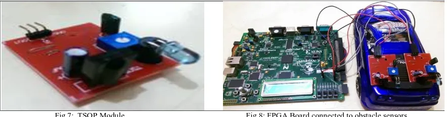
TSOP is high whenever it receives a fixed frequency and low otherwise. The on-board LED indicator helps user to check status of the sensor without using any additional hardware. The power consumption of this module is low.
Fig.7: TSOP Module Fig 8: FPGA Board connected to obstacle sensors
The TSOP module is than interfaced with FPGA board in which controling logic is embedded using Xilinx software. The FPGA than processes the data received from TSOP module and decide the logic. The hardware implementation is shown in fig.8. It shows FPGA board connected to the obstacle sensors which is embedded in demo car.When obstacle is present, the tail lights connected to demo car is ON , pratically leading to the concept of automatic braking
.
B. SIMULATION RESULT:
The simulation results of system is shown in fig.9, it shows the outputs of sensor1 and sensor2. The outputs of both the sensors are processed by controller and corresponding outputs (logic) are indicated by tail lights.
Fig 9: Simulation result
C. HARDWARE ANALYSIS:
a. RTL Schematic
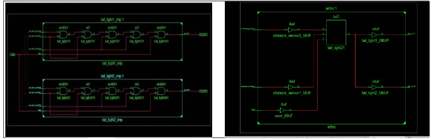
Fig.10 gives us the RTL schematic using Xilinx tool. RTL View is a Register Transfer Level graphical representation of your design. It gives a clear picture of the hardware components present in the system. This representation (.ngr file produced by Xilinx Synthesis Technology (XST)) is generated by the synthesis tool at earlier stages of a synthesis process when technology mapping is not yet completed. The goal of this view is to be as close as possible to the original HDL code. In the RTL view, the design is represented in terms of macro blocks, such as adders, multipliers, and registers. Standard combinatorial logic is mapped onto logic gates, such as AND, NAND, and OR. b. Technology Schematic:
Viewing this schematic allows you to see a technology-level representation of your HDL optimized for a specific Xilinx architecture, which might help you discover design issues early in the design process.
Fig 10:RTL Schematic view Fig 11:Technology Schematic view
c. Synthesis Report:
Fig 12: Device Utilization Summary:
Fig 12. gives the device utilization summary of our system which indicates number of inputs, IOs ,slices utilized. In timing summary fig13. it gives the net propagation delays between the different inputs and outputs in our design. The system is capable to attain maximum frequency of 160MHZ and static power required is 0.034W.
Fig13: TimingSummary
IV.CONCLUSION AND FUTURE WORK
The whole system works only while reversing the vehicle. When the sensor senses any obstacle behind the vehicle, it sends signal to the control unit (FPGA). FPGA which act as a controller logic is designed with the help of FSM, which will sense the object according to the digital input and action will be taken accordingly.
For a future development of this project, the Logic Controller designed can be enhanced by applying more rules. By then, it can produce better response. The response should be better and can be applied to a real hardware model to observe the real response and yet can improve the system. The proposed system can be replaced by an ASIC in future.
REFERENCES
[1] Love, A B. , "A precise short range radar for anti-collision systems with automatic braking" ,Consumer Applications of Radar and Sonar, IEE Colloquium. Page no. “4/1","4/6 ","IET Conference Publications", 25 May 1993, http://ieeexplore.ieee.org.
[2] Chi-Chun Yao; Chia-Feng Lin; Kuang-Jen Chang , "A brake strategy for an automatic parking system of vehicle", Vehicle Power and Propulsion Conference , vol., no. , VPPC '09.IEEE, pp.798,802 ,2009. http://ieeexplore.ieee.org
[3] T.K. Bera, K. Bhattacharya, A.K. Samantaray: Evaluation of antilock braking system with an integrated model of full vehicle system dynamics. www.elsevier.com
[4] Eung Soo Kim ,“Fabrication of Auto-Braking System for Pre-Crash Safety Using Sensor” , International Journal of Control and Automation. Vol. 4, Pages: 49 - 54, March 2009.
[5] Fletcher, I; Arden, B.J.B.; Cox, C.S., "Automatic braking system control," Intelligent Control. IEEE International Symposium,vol.,no.,pp.411,414, 2003.
[6] Carla Wada, T.; Hiraoka, S.; Tsutsumi, S.; Doi, S., "Effect of activation timing of automatic braking system on driver behaviors," ,Pages: 1366 – 1369, SICE Annual Conference, 2010.
[7] Koike, Edward David Moreno: “A Control Design Approach for Controlling an Autonomous Vehicle with FPGAs”JOURNAL OF COMPUTERS, VOL. 5, NO. 3, MARCH 2010.
[8]Zhang, Z.; Xu, H.; Chao, Z.; Li, X.; Wang, C., "A Novel Vehicle Reversing Speed Control Based on Obstacle Detection and Sparse
Representation," Intelligent Transportation Systems, IEEE Transactions
,
Volume 16, Issue: 3 ,Pages: 1321 - 1334, 2015.[9] S. Kato and K.W.Wong, “Intelligent automated guided vehicle controller with reverse strategy,” J. Adv. Comput. Intell. Intell. Informat., vol. 15, no. 3, pp. 304–312, Mar. 2011.
[10] Zutao Zhang, Member, IEEE, Hong Xu, Zhifeng Chao, Xiaopei Li, and Chunbai Wang “A Novel Vehicle Reversing Speed Control Based on Obstacle Detection and Sparse Representation” IEEE Transactions on Intelligent Transportation Systems ,Vol: 16, Issue 3, June 2015.
11] Mohd Azlan Abu, Zainudin Kornain, Izzuddin Muhammad Iqbal & Muhamad Hariz Rosli “Automated Car Braking System using Labview” Industrial Electronics and Applications (ISIEA),Pages: 246 - 250 2012, IEEE Symposium on Sept. 2012.
[12] Marin Marinescu, Constatin-Ovidiu ILIE, Radu Vilau, Octavian Alexa And Daniela Voicu “Malfunction detection using spectral analysis for
automotive braking sytems” Communications (COMM)
,
Pages: 333 - 336, 2016 International Conference,
June 2016.[13] Frederik Diederichs, Tobias Schüttke, Dieter Spath “Driver Intention Algorithm for Pedestrian Protection and Automated Emergency Braking
Systems” Intelligent Transportation Systems (ITSC), 2015 IEEE 18th International Conference
,
Pages: 1049 - 1054, Sept. 2015.[14] Likun Xia, Tran Duc Chung, Khairil Anwar Abu Kassim “An automobile detection algorithm development for automated emergency braking
system” Design Automation Conference (DAC), 2014 51st ACM/EDAC/IEEE
,
Pages: 1 - 6, June 2014.BIOGRAPHY
Divya Thakur is a M.E student in Electronics and Telecommunication, Sipna C.O.E.T, SGBAU University, Maharashtra, India.
Dr.Ajay P. Thakare is Professor & H.O.D in Department of Electronics and Telecommunication, Sipna C.O.E.T, SGBAU University, Maharashtra, India.
V.