MODELING OF LOW POWER SERIAL
INTERFACE TO HIGH SPEED ETHERNET ON FPGA
Padmaneela Nallani
1,
Mr. T. Vasudeva Reddy
2 1M.Tech, Embedded systems, E.C.E Dept, BVRIT (India)
2
M.Tech (PhD), Associate Professor, E.C.E Dept, BVRIT (India)
ABSTRACT
The FPGA-based GIGABIT Ethernet MAC controller and universal asynchronous serial communication
controller are designed and connected on chip in this paper. Such functions as writing data transmitted by the
serial interface to the Ethernet controller and sending them to the network, and serially outputting network data
received by the Ethernet controller are implemented and interconnection communications between Ethernet and
the serial are achieved, possessing great practical values in system test. The code will be developed in Verilog .
Xilinx 12.4 Edition is used for simulation, functional verification, whose hardware application is verified on
Xilinx Spartan-6SLX45-3CSG324C FPGA Diligent Atlys board. The simulation results prove that the design has
reliability, stability and good applications in the data transmission test.
Keywords
:
EMAC , FPGA, Gigabit Ethernet, Serial Communication, UART And UDP IP Protocol
I INTRODUCTION
Nowadays, Ethernet is the most commonly applied LAN communication Protocol standard. Ethernet operates in various types of cables at different rates as 10/100/1000 mbps. In this paper, the Ethernet Gateway will send data as Ethernet frame format after receiving serial data, indirectly achieves serials communication, simplifies cabinet wiring and improves CPU’s efficiency. Using a flexible FPGA programming feature, a UART and
EMAC can be designed in it. If several UARTs are in it, the system has the capacity of communication with multiple serial ports. The Ethernet module provides Ethernet communication and is configured at the time of initialization. The Gateway’s function is to achieve communication between the serial devices and Ethernet.
When Gateway receives data from devices, it will choose useful data from serial data frame following the communication protocol, and send data after packaged. When it receives data from Ethernet, it first unpacks the frame and determines the port number to transfer data to its buffer and adds the synchronous heads. By combining the two, not only can network communication be achieved, but also the Ethernet interface can be flexibly converted into serial interface output, more intuitively observing and testing data transceiver and enjoying a wide range of applications.
is almost no second source available when choosing a special chip from a specific vendor, but with a reasonable effort the manufacturer can switch to another FPGA vendor, since VHDL and Verilog are standard FPGA programming languages.
II.
OVERALL
ARCHITECTURE
The architecture mainly consists of FPGA, Ethernet transceiver and level converter. Using a flexible FPGA programming feature, a UART can be designed in it. If several UARTs are in it, the system has the capacity of communication. With multiple serial ports The Ethernet module implements Ethernet communication and is configured at the time of initialization. As we can see in Fig.1, the Gateway’s main function is to achieve communication between the serial devices and Ethernet. When it receives data from devices, Gateway will choose useful data from serial data frame following the communication protocol, and send data after packaged. When it receives data from Ethernet, it firstly unpacks the frame and determines the port number to transfer data to its buffer and adds the synchronous heads.
Figure 1: Ethernet gateway block diagram
2.1 Existing System:
Separate microprocessor/Microcontroller is used for Ethernet connectivity. Increases the cost, space and power consumption.2.2 Proposed System:
FPGA based serial gateway Ethernet connectivity is achieved with serial to Ethernet. Any other interface can be built on FPGA easily.III. DESIGN IMPLEMENTATION AND STRUCTURE OF CORE
3.1 UART Interface
A serial interface is a simple way to connect an FPGA to a PC. We just need a transmitter and receiver module .In Xilinx Spartan-6 LX45 FPGA, we have USB-UART bridge interface powered by the FTDI FT232RQ.The FTDI chip then converts the signal from UART to USB and vice versa.
The USB-UART bridge is connected to the FPGA using only two signals: RX and TX, for reception and transmission. When no data is transferred, the line is idle and maintained in the high state. To send a bit
8 data bits, and finally a '1' stop bit. Then we are ready to send another byte, or remain idle in the '1' state. This is illustrated in the following diagram.
Figure 2: UART Frame format
The speed is specified in baud, i.e. how many bits-per-seconds can be sent. For example, 1000 bauds would mean 1000 bits-per-seconds, or that each bit lasts one millisecond .Common implementations of the RS-232 interface (like the one used in PCs) don't allow just any speed to be used. If you want to use 123456 bauds, you're out of luck. You have to settle to some "standard" speed. Common values are: 1200 bauds, 9600 bauds, 38400 bauds, 115200 bauds (usually the fastest you can go). At 115200 bauds, each bit lasts (1/115200) = 8.7µs. If you transmit 8-bits data, that lasts 8 x 8.7µs = 69µs. But each byte requires an extra start and stop bit, so you actually need 10 x 8.7µs = 87µs. That translates to a maximum speed of 11.5KBytes per second. The main difficulty when designing the UART is to synchronize the reception of bits with the emitter's clock. It may be out of phase with our clock, and the phase may vary over time if the frequencies do not match exactly. To solve this problem, we need a clock running faster than the baud rate, to be able sample the incoming bits at the right time. Here, we take the input clock (the constants given below assume we use the 100 MHz system clock) and generate ticks on sample at 16x the baud rate, i.e. 16 ticks per bit.
3.1.1 UART Transfer
This module is used to send bus data received from Ethernet.
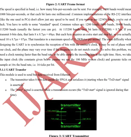
o The transmitter takes 8-bits data inside the FPGA and serializes it (starting when the "TxD start" signal is asserted).
o The "busy" signal is asserted while a transmission occurs (the "TxD start" signal is ignored during that time).
Figure 3: UART Transmitter
3.1.2 UART Receiver
indicating the start bit, the state machine enters DATA0 state. The data is received , one bit at a time from LSB to MSB in states DATA0 to DATA7.
If parity is enabled, the state machine checks the parity bit received against the parity obtained from received data. Our implementation works like that:
o The module assembles data from the RxD line as it comes.
o As a byte is being received, it appears on the "data" bus. Once a complete byte has been received, When the valid stop bit is detected, data are sent into the register "data_ready" is asserted for one clock. Note that "data" is valid only when "data ready" is asserted.
Figure 4: UART Receiver
As we know, the FPGA processing speed is far greater than peripheral transmit data rate, so once I/O buffer receives data from any serial port, the data can be read by Ethernet interface chip directly.
3.2 Ethernet Interface
LAN-based routers greatly extend the speed, distance, and intelligence of Ethernet LANs. Routers also allow traffic to travel along multiple paths. Routers, however, do require a common protocol between the router and end stations. The Ethernet module takes the input from the transmitter assigned port of the FPGA in a serial format form, and that data is transmitted to the destination system in the form of Ethernet packet.
To send data on Ethernet, you cannot just send it like that; you have to encapsulate it into an Ethernet packet. The packet contains a header with the information necessary for the data to reach its destination. The Ethernet is based on the idea of a shared medium - if a station sends a packet, everybody on the line receives it. Each Ethernet card has a unique ID (the "MAC address"), so each card can automatically discard packets meant for another station. The MAC address is 6 bytes long (48 bits), which is big enough to allow each Ethernet card on earth to have a unique number.
Gigabit Ethernet can provide communication bandwidth with 1Gb/s. Because it uses the same CSMA/CD protocol, frame format, frame length as the traditional 10/100M Ethernet network, so it is able to realize internet update smoothly and continuously based on the original slow Ethernet to protect user investment mostly. But in many applications, it calls for the realization of high-speed network data transmission without using the NIC (Network Interface Card) of PC, and transmitting the post processing data to Gigabit Ethernet. This system adopts FPGA and Gigabit NIC to meet the needs.
Gemac_ configure : MII Management Module performs PHY control and gathers the status information from it.
Packet_sender : Appends UDP/IP/Ethernet Header and leaves it to interface with MAC core Packet_Receiver: Extracts data from packet received by removing UDP/IP/Ethernet Header simple_gemac_wrapper : controls the Ethernet transmit and receive operation
Figure 5: EMAC Core
Simple gemac wrapper consists performs following operations
o TX Ethernet MAC: TX Ethernet MAC generates 1000 BASE-TX transmit GMII byte data streams in
response to the word streams supplied from the transmit logic (host). It performs the required algorithms, takes care for the IPG, computes the checksum (FCS) and monitors the physical media (by monitoring Carrier Sense and collision signals).
o RX Ethernet MAC: RX Ethernet MAC interprets 1000 BASE-TX transmit GMII receive data byte stream and supplies correctly formed packet word streams to the host. It searches for the SFD (start frame delimiter) at the beginning of the packet, verifies the FCS and detects any errors in Data or receive code violations
o MAC Control Module: The function of this module is to implement the full-duplex flow control. The
MAC Control Module consists of three sub modules that provide the following functionality:
o Control Frame Detector : Checks the incoming frames for the control frames. Control frames can be discarded or passed to the host. When a PAUSE control frame is detected, it can stop the TX module From transmitting for a certain period of time.
o Control Frame Generator: When there is a need to stop the transmitting station from the transmission (flow control in full duplex mode), a PAUSE control frame can be send to it.
o TX/RX Ethernet MAC Interface: MAC Control module is connected between the host interface and the Tx and the Rx
MAC modules. Signals from the host are passed by to the Tx MAC in certain occasions and vice versa.
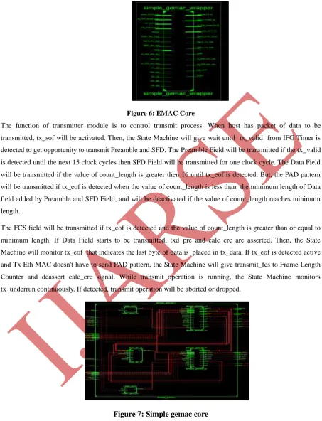
Figure 6: EMAC Core
The function of transmitter module is to control transmit process. When host has packet of data to be transmitted, tx_sof will be activated. Then, the State Machine will give wait until tx_valid from IFG Timer is detected to get opportunity to transmit Preamble and SFD. The Preamble Field will be transmitted if the tx_valid is detected until the next 15 clock cycles then SFD Field will be transmitted for one clock cycle. The Data Field will be transmitted if the value of count_length is greater then 16 until tx_eof is detected. But, the PAD pattern will be transmitted if tx_eof is detected when the value of count_length is less than the minimum length of Data field added by Preamble and SFD Field, and will be deactivated if the value of count_length reaches minimum length.
The FCS field will be transmitted if tx_eof is detected and the value of count_length is greater than or equal to minimum length. If Data Field starts to be transmitted, txd_pre and calc_crc are asserted. Then, the State Machine will monitor tx_eof that indicates the last byte of data is placed in tx_data. If tx_eof is detected active and Tx Eth MAC doesn't have to send PAD pattern, the State Machine will give transmit_fcs to Frame Length Counter and deassert calc_crc signal. While transmit operation is running, the State Machine monitors tx_underrun continuously. If detected, transmit operation will be aborted or dropped.
Figure 7: Simple gemac core
Fig 7 shows Overall architecture of Simple_Gemac core which performs transmission and Reception of Data from Physical Layer simple_gemac_tx performs Transmission and simple_gemac_rx performs Reception. flow_ctrl_tx controls the transmission
IV.
FLOW
CHART
V. SIMULATION & RESULTS
In this project we evaluated the integration of packet transmission and reception capabilities in 1GbE Ethernet Transmitter devices. The MAC architecture was first analyzed to design a switching system that can exploit the processing mechanism of the MAC Ethernet Transmitter layer. The proposed architecture was implemented and validated on a synthesizer. Its resource demand was evaluated to address the scalability of the architecture and to detect the most demanding modules.Xilinx12.4 Edition will be used for functional simulation and verification of results. Xilinx ISE will be used for synthesis. Fig 8 shows the RTL Schematic & technology schematic of the proposed system. The UARTs have worked correctly for a long time.
In order to test the presented solution, communication between FPGA and computer is tested by using a windows application. A convenient way for testing solution is connecting FPGA to a PC and trying to communicate with FPGA using a windows based application. In order to be able to send and receive packets with any IP addresses, manipulation in network adapter of windows is necessary. Dock light application which can send and receive custom packets is used . Wire shark can also be used to analyze the Packets
Figure 9: Results in Windows application (Dock light
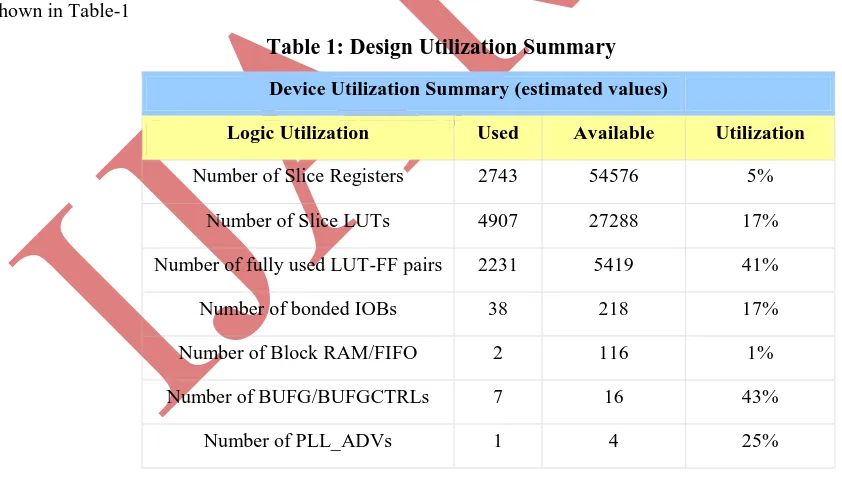
)In Docklight Application blue color data is sent and Red color data is Received. When data is transmitted from IP 169.254.77.1 and on port 4660 we have received same on UART in com port and when we transmitted data from uart that is received on particular port.The Design utilization summary of the Designed Ethernet MAC is shown in Table-1
Table 1: Design Utilization Summary
Device Utilization Summary (estimated values)
Logic Utilization Used Available Utilization
Number of Slice Registers 2743 54576 5%
Number of Slice LUTs 4907 27288 17%
Number of fully used LUT-FF pairs 2231 5419 41%
Number of bonded IOBs 38 218 17%
Number of Block RAM/FIFO 2 116 1%
Number of BUFG/BUFGCTRLs 7 16 43%
Number of PLL_ADVs 1 4 25%
VI. SUMMARY AND CONCLUSION
allow further upgrade for system. Low cost, as the multi card solution can come in single FPGA card with small modules around it communicating local area no of systems transferring the data on system to anther system Low power in comparison with multi card solution using Xilinx ISE 12.4, Lot of scope for adding additional functionality on FPGA. In safety critical real-time application, using Real-time Transport Protocol (RTP) for communication is an excellent option. Since RTP is used in transferring video and image, it could be useful in vision systems which are developed in a FPGA. Presented solution provides developers with fertile ground in developing the RTP or other higher protocols.
ACKNOWLEDGMENTS
We would like to give thanks to AVANTEL LTD for their support and Everyone who helped me directly or indirectly to complete this Project
REFERENCES
[1] Davicom datasheet 10/100 mbps fast ethernet physical layer tx/fx single chip transceiver. pages 1 { 41,September 2008.
[2] A. L”ofgren, L. Lodesten, S. Sj ¨oholm, and H. Hansson,“An analysis of FPGA-based UDP/IP stack parallelism forv embedded Ethernet connectivity,” in Proceedings of the 23rd IEEE NORCHIP Conference,
November 2008, pp. 94–97.
[3] Ethernet h10032.www1.hp.com/ctg/Manual/bpe50027.pdf
[4 ] Shouqian Yu, Lili Yi, Weihai Chen, Zhaojin Wen,“Implementation of a Multi- channel UART Controller Based on FIFO Technique and FPGA,” industrial Electronics and Applications, Harbin, China, May2007, pp.
2633- 2638. |
[5] N. Alachiotis, S. A. Berger, and A. Stamatakis, “Efficient PC-FPGA Communication over Gigabit Ethernet,” in CIT, 2010,pp. 1727–1734.
[6] N. Padmaneela and T.Vasudev Reddy, “FPGA Implementation of Low Power Serial to High Speed Data Networks,” in IJRITCC, 2014,volume 2 ,Issue 8, pp.2377 – 2383.
[7] “User datagram protocol,” RFC 768 (Standard), Internet Engineering Task Force, August 1980.
[8] Tinoosh Mohsenin , ( 2004) Rice University, ”Design and Evaluation of FPGA- Based Gigabit-Ethernet/PCI Network Interface Card Thesis”
[9] Yafang Wang, Cheng Zhang, Yanli Hou,Boning Hu, (2010) “Implementation of Gigabit Ethernet Network based on SOPC”, Asia Pacific Conference on Wearable Computing Systems, pp.341-343.
[10] hearlink.tripod.com/CandCDB/GMII_REPORT.pdf
[11] http://www.joelw.id.au/FPGA/CheapFPGADevelopmentBoards
[12] C. Kachris, et al., (2008) “Design and performance evaluation of an adaptive FPGA for network applications”, Microelectron. J (2008) , doi: 10.1016/ j.mejo. 2008.05.011.