18th International Conference on Structural Mechanics in Reactor Technology (SMiRT 18) Beijing, China, August 7-12, 2005 SMiRT18-W101-10
DETERMINISTIC AND PROBABILISTIC ANALYSIS OF FUEL
CHANNEL – GRAPHITE GAS-GAP CLOSURE IN IGNALINA NNP
REACTOR
Juozas Augutis
Lithuanian Energy Institute, Lithuania
Phone: +37037401973, Fax:
+37037351271
E-mail: [email protected]
Barry J. Marsden
Manchester University, UK
Gintas Dundulis
Lithuanian Energy Institute, Lithuania
Jurgita Simaityte
Lithuanian Energy Institute, Lithuania
ABSTRACT
To maintain thermal contact between the fuel assembly and the graphite moderator, RBMK design reactors employ graphite split rings, which are alternatively tight on the pressure tube or tight on the graphite brick central bore. The split in the graphite rings allows a helium / nitrogen gas mixture to flow up the fuel channel. This prevents oxidation of the graphite and can be sampled to detect pressure tube leaks. The initial clearance between the rings and pressure tube or graphite brick is approximately 2.7 mm (1.35mm each side). Due to material property changes of the pressure tubes and graphite during operation of the reactor, the size of the clearance between the rings and the pressure tube/brick, called the “gas-gap”, varies. Closure of these gaps has been identified as a possible safety case issue by reactor designers and by independent reviews carried out as part of TACIS reviews and as part of the Ignalina Safety Analysis Report.
The overall objective of the studies is to aid prediction of the gas-gap closure process, and help to identify a suitable monitoring strategy for gas-gap closure that could be used for any RBMK reactor. The deterministic assessments based on the Ignalina RBMK-1500 reactors have carried out, modelling the behaviour of the graphite under irradiation and have predicted graphite bore diameter changes that are in good agreement with the measurements of graphite bore diameters taken at Ignalina Nuclear Power Plant (NPP). A probabilistic model has been developed using the actual results of the deterministic calculations with non-linear graphite behaviour. Statistical analysis of the measurements of tube and graphite diameters taken from unit 1 and 2 at Ignalina NPP has been carried out.
Keywords: Graphite bore, pressure tube, fuel channels, gas gap.
1. INTRODUCTION
The RBMK reactor is designed to use a graphite moderator in the form of graphite bricks which surround Zirconium-Niobium channels (or “pressure tubes”) containing the nuclear fuel and coolant. The pressure tube is initially positioned in place by a series of graphite rings that are alternately in contact with the inner bore hole of the graphite bricks and the outer perimeter of the pressure tubes. The initial design was to provide a nominal 2.5-3
mm gap between the pressure tubes and the rings. Figure 1 presents the scheme of fuel channel, graphite rings and graphite bore and the position of the gas gap.
Safety Analysis Report (SAR, 1996) and Review of Safety Report (RSR, 1997) of the Ignalina NPP concluded that closure of the gas gap between the fuel channels and graphite bricks is one of the most important reactor operation lifetime criteria.
d7 9 .5
d8 8+ 0 .2 3
d 2 5 0- 1 .0
d 1 1 4 .3- 0 .2 3 d1 1 1 .0+ 0 .2 3
d 9 1 .0+ 0 .2 3
d 8 8 .0
d 1 1 4 .0+ 0 .2 3
- 0 .6
F u e l
C h a n n e l
G r a p h it e
b r ic k
G r a p h it e
r in g s
Fig. 1. Scheme of the fuel channel.
2. RBMK GRAPHITE MATERIAL PROPERTIES
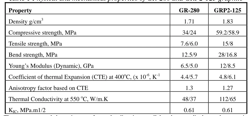
The graphite used in the cores of the RBMK reactors is a medium grained anisotropic polycrystalline graphite product designated type GR-280, the graphite rings are manufactured from another graphite type GRP2-125, which has a higher thermal conductivity, strength and density. Typical virgin properties for these graphites are given in Table 1 below.
Table 1 Physical and mechanical properties of GR-280 and GRP2-125 graphite
Property GR-280 GRP2-125
Density g/cm3 1.71 1.83
Compressive strength, MPa 34/24 59.2/58.9
Tensile strength, MPa 7.6/6.0 15/8
Bend strength, MPa 12.5/9 28/16.8
Young’s Modulus (Dynamic), GPa 6.5/5.0 12/8.5
Coefficient of thermal Expansion (CTE) at 400oC, (x 10-6, K-1 4.4/5.7 4.8/6.1
Anisotropy factor based on CTE 1.3 1.27
Thermal Conductivity at 550 oC, W/m.K 48/37 112/65
KIC, MPa.m1/2 0.61 0.61
Note: The numerator and denominator refer to the direction parallel and perpendicular to the extrusion axis, respectively.
Irradiation data giving dimensional changes and property changes such as the coefficient of thermal expansion, Young’s modulus, strength, thermal conductivity and irradiation creep rate as a function of irradiation dose1 have been obtained in material test reactor programmes carried out at the Kurchatov Institute in Moscow. This data along with various design rules are part of the Russian design code “Norms for strength analysis of standard graphite units and components of channel-type uranium-graphite reactors”, NGR-01-90. RDIPE, 1991”. The most
1
4846 Copyright © 2005 by SMiRT18
relevant of these properties to this study is dimensional change for type GR-280 graphite. During the operation of a graphite-moderated reactor, fast neutron irradiation causes dimensional and material property changes to the graphite. During the first half of the reactor life, after a short initial period of expansion, the RBMK graphite shrinks, both axially and radially, due to dimensional changes. If this shrinkage were to continue, the gap between the graphite moderator brick and the graphite rings would be taken up, however there after about 1% linear radial shrinkage “turn around occurs and the graphite starts to expand, see Fig. 2 and Fig. 3. This behavior causes the diameter of the bore in the graphite block to reach a minimum value (“turn- around”) and start to expand in the second half of reactor life. This is normal graphite behaviour under irradiation (Brocklehurst, 1993). In addition, the zirconium pressure tube expands due to irradiation creep. To allow for irradiation-induced graphite shrinkage and fuel channel tube expansion there is a gap between the fuel channel tube and the graphite moderator bricks.
-4 -3.5 -3 -2.5 -2 -1.5 -1 -0.5 0 0.5
0 5 10 15 20 25 30
Dose n/cm2 x 1021 (En>0.18 MeV)
Di
me
ns
iona
l Cha
nge
% Para (Temperature 350-420 oC}
Para {Temperature 500-550 oC}
Para (Temperature 650-750 oC}
Fig. 2 Graphite dimensional change parallel to the extrusion direction.
-1.5 -1 -0.5 0 0.5 1
0 5 10 15 20 25
Dose n/cm2 x1021 (En>0.18 MeV)
Dim
e
nsional Change %
Perp (Temperature 350-420 oC}
Perp (Temperature 500-550 oC}
Perp (Temperature 650-750 oC}
3. STATISTICAL ANALYSIS OF THE MESARUEMENT DATA
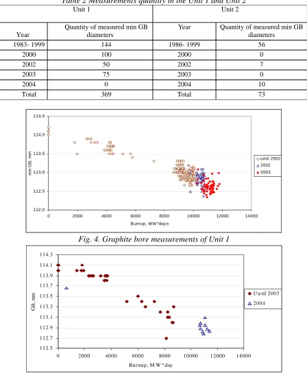
Graphite bore diameters and pressure tube diameters have been subject to continuous inspection and measurement since the start of the operation of the Ignalina NPP reactors (1983). Until 2004 there were performed 369 measurements of graphite bore in Unit 1 and 73 measurements in Unit 2 (Table 2). Data of graphite bore minimal diameter in the channel measurements are presented in Fig. 4 of Unit 1 and in Fig. 5 of Unit 2. The similar behavior of nonlinear graphite bore diameters was considered. The number of fuel channels measurements was 1682 measurements in Unit 1 and 1460 in Unit 2.
Table 2 Measurements quantity in the Unit 1 and Unit 2
Unit 1 Unit 2
Year
Quantity of measured min GB diameters
Year Quantity of measured min GB diameters
1983- 1999 144 1986- 1999 56
2000 100 2000 0 2002 50 2002 7 2003 75 2003 0 2004 0 2004 10 Total 369 Total 73
112,0 112,5 113,0 113,5 114,0 114,5
0 2000 4000 6000 8000 10000 12000 14000
B urnup, M W *days
min G
B
, mm until 2002
2002 2003
Fig. 4. Graphite bore measurements of Unit 1
112.5 112.7 112.9 113.1 113.3 113.5 113.7 113.9 114.1 114.3
0 2000 4000 6000 8000 10000 12000 14000
Bur nup, M W *day
GB
, m
m U n til 2003
2004
4848 Copyright © 2005 by SMiRT18
The nonlinear shape change of graphite under the action of temperature and neutron flux is well known (Bougaenko, 1994). But the behavior of individual graphite blocks can differ strongly. When predicting the change in the diameter of openings in individual graphite blocks, the geometric parameters of a block, the position of the block in the reactor, the energy production of the channel, and other factors must be taken into account. The dependence of the minimum diameter on energy production was obtained using the ABAQUS code (Jones, 1995, Hopkinson, 2003 and Augutis, 2001).
The measurements of graphite bore diameter were performed in 6 directions. Such type of measurements showed, that graphite rings do not have geometrically regular shape of the circle. Analysis of the data confirmed that graphite rings have ellipse type form (Fig. 6).
Minimal GB diameter
Maximal GB diameter
Fig. 6. Schematic view of graphite ring cross-section
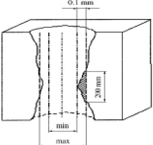
According to the regulations (RSR, 1997), the gas gap in a channel is considered to be closed if the graphite touches the surface of the pressure tube along the entire perimeter in a zone of at least 200 mm. From the first time the graphite touches the surface of a channel to complete closure of the gap in a 200 mm zone, the diameter of the graphite bricks decreases on the average by 0.1 mm (Fig. 7).
Fig. 7. Diagram of a section of a graphite brick.
4. DETERMINISTIC ASSESSMENT OF GRAPHITE/TUBE BEHAVIOUR USING FINITE ELEMENT METHOD
The analysis of the behaviour of the RBMK brick, rings and tube was carried out using a standard commercial finite element code (ABAQUS). A two-dimensional model of the brick/ring/tube system was used which approximates the true geometry of the split graphite rings. As irradiation creep in graphite is non-isotropic, that is it has a Poisson’s ratio in creep of less than 0.5, the standard creep equations supplied with the finite element package were not applicable, therefore the anisotropic, non-linear constitutive equations for irradiated RBMK graphite was programmed into ABAQUS via a user material subroutine UMAT. The method is described in detail by (Iyoku, 1991) and has been used for graphite assessments in UK Magnox and AGRs, the Japanese HTTR and various other RBMK reactors (Bougaenko, 1994 and Marsden, 1995).
The ABAQUS graphite finite element model accounts for reactor irradiation temperature and dose history, property and dimensional changes in both the graphite core bricks and graphite rings perpendicular to the extrusion direction and parallel to the extrusion direction. The changes to the graphite properties and irradiation creep law as a function of dose and temperature are based on data from Russian material test reactor experiments.
a) b)
Fig. 8 Axi-symmetric (a) and two-dimensional (b) finite element meshes
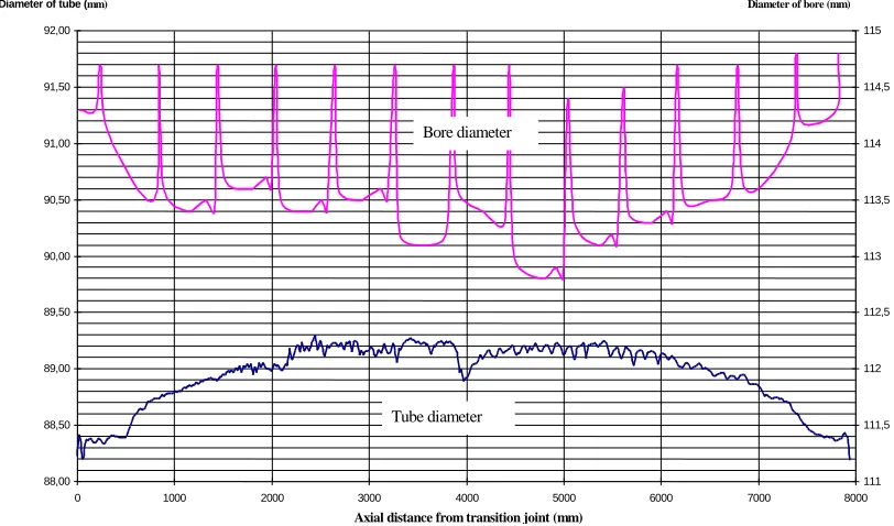
The diameters of graphite columns and zirconium tube are varies along the axis of tube. The changes of these diameters are presented in Fig. 9. Therefore a separate set of finite element calculations was carried out for each of the eight central bricks in the column, for the region where the dimensional changes are the greatest. These used axially varying data appropriate to the modelled brick and the power (and dose) history for Ignalina NPP Unit 1. The data from these calculations have been compared against measurement data for bore diameter change and thermocouple temperatures from the station.
88,00 88,50 89,00 89,50 90,00 90,50 91,00 91,50 92,00
0 1000 2000 3000 4000 5000 6000 7000 8000
Axial distance from transition joint (mm)
Diameter of tube (mm)
111 111,5 112 112,5 113 113,5 114 114,5 115 Diameter of bore (mm)
Bore diameter
Tube diameter
Fig. 9 The diameters of graphite bricks and zirconium tube along the axe of tube
4850 Copyright © 2005 by SMiRT18
account for the non-linearity of the graphite bore closure for predicting the closure of the gas-gap in RBMK reactors is clearly illustrated.
1 1 2 , 2 1 1 2 , 4 1 1 2 , 6 1 1 2 , 8 1 1 3 , 0 1 1 3 , 2 1 1 3 , 4 1 1 3 , 6 1 1 3 , 8 1 1 4 , 0 1 1 4 , 2
0 2 0 0 0 4 0 0 0 6 0 0 0 8 0 0 0 1 0 0 0 0 1 2 0 0 0 1 4 0 0 0
M W * d a y s
G
B
di
a
m
et
er
s
,
m
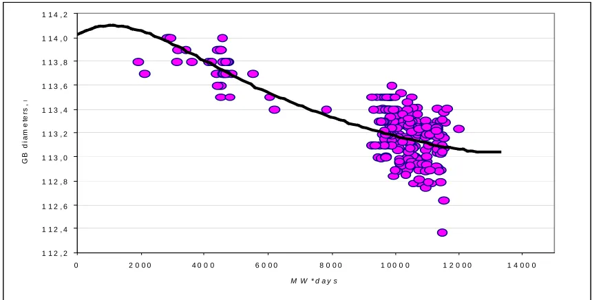
Fig. 10 Comparison of brick calculations with measurements.
5. PROBABILISTIC ASSESSMENT OF GRAPHITE/TUBE BEHAVIOUR
The basic method for the evaluation of the gas gap existence. As gas gap depends on many factors the value of gas gap appears as random value. In general, the behavior of pressure tube and graphite bore diameters are defined according to the deterministic laws. For the pressure tube diameter behavior the linear trend was applied. Since there was available quite big amount of repetitive measurements of pressure tube diameters, it was possible to check the accuracy of the linear modeling, which appeared to be very high.
For graphite diameters prognosis –the results of modeling using ABAQUS code were used. The scheme of the ABAQUS modeling is presented in the Fig. 10.
To estimate the probability that a gas gap between pressure tube and graphite bore exists, a mathematical model of the behavior of the diameter in graphite blocks and of the channels was constructed. The graphite bore diameter can be determined from the formula:
ξ
+
∆
+
=
(
)
)
(
N
d
N
d
G GT (1)where N is the energy production of the channel; dG(N) is the diameter of the graphite block with the energy production of the given channel; dGT(N) is the minimum diameter in a graphite block with energy production N (the values obtained using the ABAQUS code); ∆ is the difference between the minimum and maximum diameter of an opening in a graphite block; ξ is the normal random quantity N(0, σG); σGis the standard deviation of the diameter of the openings in the graphite blocks. The correspondence of the statistical data to a normal distribution of the random quantity ξ was checked according to the χ2criterion.
The outer diameter of the pressure tube is determined as follows:
η
+
=
(
)
)
(
N
d
N
d
K TK (2)where dK(N) is the diameter of the channel with energy production N; dKT(N) is the average outer diameter of pressure tube with energy production N; η is a normal random quantity N(0, σK); σKis the standard deviation of the diameter of pressure tube.
Thus, we find that the diameter of graphite blocks in the channels is a normally distributed random quantity. The probability of closure of a gas gap can be determined from the formula
(
)
∞∫
∞ −
=
<d N F x p x dx
N d
P G( ) K( ) G( ) K( ) (3)
where FG(x) is the distribution function of the random value dG(N), and pK(x) is the distribution density of the random value dK(N).
The number of graphite blocks which must be measured to estimate the closure probability for a gas gap with required confidence level α is determined as follows. The confidence intervals with the same confidence level
α for average values E(dG(N)) and E(dK(N)) are constructed from measurements of the diameter of the openings in the graphite blocks and technological channels. The width of the confidence intervals depends on the energy production. The confidence level is choused so that the load limit of the confidence interval for graphite and the upper limit of the confidence interval for a channel intersect at a given energy production N, i.e., we solve the equation
(
)
(
)
(
(
)
)
(
(
)
) (
(
)
)
.
1
1
2
1
1
2
2 2N
d
E
N
d
E
N
N
N
N
n
t
N
N
N
N
n
t
K G K K K K K n G G G G G n i K i G−
=
=
−
−
+
+
+
−
−
+
+
∑
∑
α
σ
σ
α
(4)Here nGand nKare, the number of measurements for graphite blocks and technological channels, respectively;
NGis the average energy production of the measured graphite block; NGiis the energy production of the i th
graphite block; NKis the average energy production of the channels; NKiis the energy production of i
th
channel; tn(α/2) is Student’s criterion with n degrees of freedom and significance level α.
Solving the last with all parameters except nGgiven, we obtain the number of graphite blocks which must be measured to estimate the closure probability for a gas gap with the required confidence level α. The closure probability for the first gap with energy production N in this case will be P = (α/2)2.
4. RESULTS AND CONSLUSIONS
The system developed for monitoring and estimating the residual gas gap between graphite blocks and the technological channels in an RBMK-1500 reactor makes it possible to trace with a high confidence level and estimate the process of variation of the gas gap. The deterministic model, constructed on the basis of the finite-elements method, and the mathematical apparatus developed for calculating the closure probabilities for gas gaps, which is based on statistical data obtained from measurements of the diameters of openings in graphite blocks and technological channels, can be easily adapted to other reactors. To do so, it is necessary to take account of the individual data obtained over the period of operation of a specific reactor. Experience gained for many years of using this method for estimating gas gaps at the Ignalina nuclear power plant has confirmed the main assumptions concerning the variation in the diameter of the openings in graphite blocks, the outer diameter of the technological channels, and the gas gap itself. The method developed makes it possible to choose cells for monitoring in a manner so as to extract from the reactor the channels for which the gap closure probability is highest. Since after the diameter of the openings in graphite cells has been measured new channels are inserted, the gap is restored to approximately 50% of the initial value.
REFERENCES
[1] SAR-1996, (1996), Ignalina Safety Analysis Report. Final Edition issued by Vattenfall Nuclear Project AB for the Ignalina Nuclear Power Plant.
[2] RSR-1997, (1997), Review of the Ignalina Nuclear Power Plant Safety Analysis Report,. [3] Brocklehurst J E, Kelly J E. (1993), Jrnl. of Carbon Vol. 31, No. 1. pp. 55-178,
[4] Bougaenko S. et al., (1994), “Introduction to the safety assessments related to RBMK graphite reactors,” in: Proceedings of the International Conference on Thermal Reactor Safety Assessment,.
[5] Jones C., Davies M., Marsden B., et al., (1995), “Assessment of the stresses and deformations in a RBMK graphite moderator brick,” in: Proceedings of the IAEA Specialists Meeting on Graphite Moderator Lifecyle Technologies.
[6] Hopkinson K. L., Marsden B. J., Dundulis G., Kopustinskas V., Liaukonis M., Augutis J. and Uspuras E., (2003), Jrnl. of Nucl. Eng. Design, Vol. 223, pp. 117–132.
[7] Augutis J., Uspuras E., Liaukonis M., (2001), Jrnl. of Nucl. Eng. Design, Vol. 203, pp. 195–207 [8] Iyoku T, Ishihara M. (1991), Jrnl. of Nuclear Science and Technology, Vol. 28, No. 10. pp. 921-931. [9] Marsden B. J., Jones C. J., Davies M. A., Bougaenko S. E., Baldin V. D., Demintievski V. N., Rodtchenkov B.