ISSN(Online): 2320-9801
ISSN (Print): 2320-9798
I
nternational
J
ournal of
I
nnovative
R
esearch in
C
omputer
and
C
ommunication
E
ngineering
(An ISO 3297: 2007 Certified Organization) Website: www.ijircce.com
Vol. 5, Issue 5, May 2017
To Measure the Performance of DWDM Ring
Network Using RZ and NRZ Modulators
Ramandeep Kaur, Dr. Renu Dhir
Research Scholar, Dept. of CSE, NIT Jalandhar, Punjab, India
Associate Professor, Dept. of CSE, NIT Jalandhar, Punjab, India
ABSTRACT: In this modern world of technology, there has been a huge upsurge in the demand of bandwidth in modern telecommunication networks. As we always need a high rate of data transmission, there are various techniques which we are using to achieve our objectives. Dense wavelength division multiplexing appears as the technology for developing the transmission capacity of carrier networks. DWDM technology gives an extraordinary bandwidth as currently available systems support up to about 100 wavelengths per fibre, it enables a single mode fibre to have several hundred gigabits per second of information to get and receive. In this thesis, the investigation on various modulation methods for transmit the data with 450 GBPS has been reported. The main target of this research is to choose the best modulation method from RZ and NRZ with 30 km ring span length using 45 numbers of channels with the speed of 450 GBPS. In this manuscript, we investigate the performance on the basis of baseband spectrum, eye diagram and BER.
KEYWORDS: DWDM, OADM, RZ, NRZ.
I. INTRODUCTION
DWDM is the multiplexing technnique of fiber optics transmission system that is used to increase the bandwidth of an optical fiber such that several different signals can be transported simultaneously on the fiber. DWDM technology enables a single mode fibre to have several hundred gigabits per second of information to get and receive [1]. In telecommunication optical network the dense wavelength division multiplexed system is the standard technology in it, which ranges to thousands of kilometers from a few kilometers. Commercial DWDM systems were used wavelengths modulated at the range of 2.5, 10, or 40 GBPS which covers the C and L spectral band spectral range. These wavelengths can be dropped and added from the multi-wavelength network fibre at surrounding locations for the conversion of electronic format to the optical formats. The adding and dropping of wavelength is done using OADM (Optical add Drop Multiplexer) [2].
RZ and NRZ are the modutaion formats used to modulate the signals. RZ is Return-To-Zero, in which each signal drop returns to zero between each pulse. Each pulse representing bit 1 is shorter than the bit slot. [3] NRZ is nonreturn-to-zero, in which the binary code 1 represents the positive voltage and 0 represents the negative voltage. NRZ pulses have more energy as compare to RZ pulses.[4]
II. RELATED WORK
In [5] authors introduced the concept of network topologies, and network architectures for metro optical rings networks and also investigate the main requirements that directly point the importance of service providers. The authors review the general requirements and discussed the components of the network that would enable the step within the evolution-growth developing of the DWDM ring.In [6] author described WDM divided-ring network architecture by nodes that used one stable sender and stable receivers. The usage of a metropolitan network, it could be shown by the simulation itself, which tells that how a easily slotted MAC applications and protocol can be implemented in this network to get
better bandwidth consumption. In [9] authors described the fast growth and increase in demand of internet. By
ISSN(Online): 2320-9801
ISSN (Print): 2320-9798
I
nternational
J
ournal of
I
nnovative
R
esearch in
C
omputer
and
C
ommunication
E
ngineering
(An ISO 3297: 2007 Certified Organization) Website: www.ijircce.com
Vol. 5, Issue 5, May 2017
ultra long haul optical system for maximum capacity transmission where wavelengths added and dropped was not a
main issue in early days. Data transmission working and performance was also evaluated and the impact of extinction
ratio of WB on performance was reviewed. In [7] author described how to reconfigure optical nodes to add in the
network and how it was dropped from the network this is all based on multiplexers 1˟N wavelength-selective switches
are elaborate to depend on DWDM networks with greater flexibility and higher capacity in wavelength routing. In [8] author present the optical add and drop multiplexers within very wide dense wavelength division multiplexing scheme in the communication networks of metro optical which had modelled and parameterized analysed over broad collection of very affecting parameters. In addition to this, the authors had also analyzed the changeable structural changes and maximum capacity and higher possible transmission bit rates.
III. MATHEMATICAL FORMULATION
N: Set of nodes of the ring network.
L: Length between the different nodes of the ring network.
K ={1,2}: set of directions (1 =clockwise and 2 = counter clockwise).
F: Spectral width of a frequency slice.
S: Total available spectrum width on each link, expressed as an integer multiple of F.
G: Width of the guard band (GHz) used to separate adjacent spectrum paths, expressed as an integer multiple
of F.
T : Maximum channel bandwidth of a transceiver (GHz), expressed as an integer multiple of F.
P: Power Laser
C: Number of channels.
λ : Channel wavelength.
CS: Channel Spacing.
T: Total ring span length.
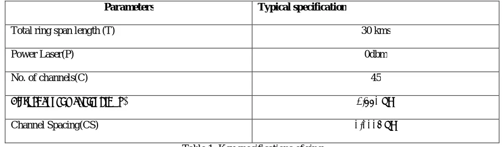
IV. KEY SPECIFICATIONS OF DWDM BASED METROPOLITAN RING NETWORK FOR 30 KMS RING SPAN LENGTH
Parameters Typical specification
Total ring span length (T) 30 kms
Power Laser(P) 0dbm
No. of channels(C) 45
First channel wavelength (λ) 1.550 μm
Channel Spacing(CS) 0.0004 μm
Table 1: Key specifications of ring
V. RESULTS AND DISCUSSIONS
ISSN(Online): 2320-9801
ISSN (Print): 2320-9798
I
nternational
J
ournal of
I
nnovative
R
esearch in
C
omputer
and
C
ommunication
E
ngineering
(An ISO 3297: 2007 Certified Organization) Website: www.ijircce.com
Vol. 5, Issue 5, May 2017
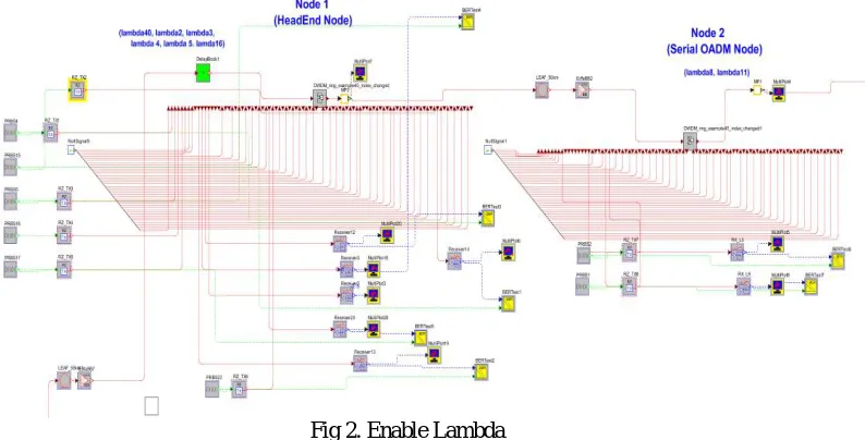
Fig.1 Simulation setup for 45 channels DWDM-OADM Optical Ring Network
In figure 1, simulation setup for 45 channels DWDM optical ring network is shown. In this 45 number of input channels are transmitting on transmitter side and 45 outputs are received on receiver side. Using optical fibre, all nodes are connected with each others. There may be the posibilities of errors during transmission; a null pointer is used to control the errors during transmission. A single channel can transmit upto 10 GBPS data on the network. We can attach
45 no of channel and the data transfer rate with these are 45*10=450 GBPS
.
Fig 2. Enable Lambda
ISSN(Online): 2320-9801
ISSN (Print): 2320-9798
I
nternational
J
ournal of
I
nnovative
R
esearch in
C
omputer
and
C
ommunication
E
ngineering
(An ISO 3297: 2007 Certified Organization) Website: www.ijircce.com
Vol. 5, Issue 5, May 2017
Fig.3. NRZ & RZ Modulator
Fig 4.6 shows the RZ and NRZ modulator. In RZ, signal drops return to zero between each pulse. This takes place even
if a number of consecutive 0s or 1s occur in the signal. It does not need to send a different clock alongside the signal because it uses self clocking signals. In NRZ, binary code 1 represents the positive voltage while 0 represent the negative voltage. As compare to RZ code, NRZ pulses have more energy. NRZ is not a self clocking signal so it required some additional clock alongside the signal.
The performance of the system is analyzed for two node, node 1 and node 4 as node one is starting node and node 4 as intermediate node. The result shows the successful transmission of 45channels with channel spacing of 0.4 nm and 10 Gpbs data on each channel. The proposed system is further analyzed for the modulation format RZ as presented in above for NRZ.
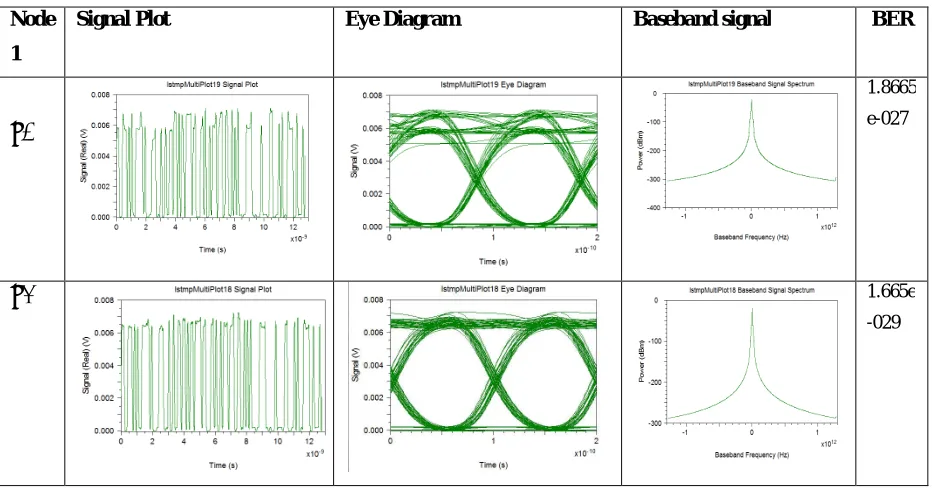
Modulation format NRZ: NODE 1
Node
1
Signal Plot Eye Diagram Baseband signal BER
λ1
1.8665
e-027
λ3
1.665e
ISSN(Online): 2320-9801
ISSN (Print): 2320-9798
I
nternational
J
ournal of
I
nnovative
R
esearch in
C
omputer
and
C
ommunication
E
ngineering
(An ISO 3297: 2007 Certified Organization) Website: www.ijircce.com
Vol. 5, Issue 5, May 2017
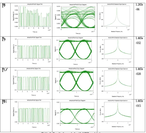
λ4
1.265e-06
λ5
1.465e-032
λ16
1.465e-028
λ40
1.465e-015
Table 2: Results for node 1 with NRZ modulation
ISSN(Online): 2320-9801
ISSN (Print): 2320-9798
I
nternational
J
ournal of
I
nnovative
R
esearch in
C
omputer
and
C
ommunication
E
ngineering
(An ISO 3297: 2007 Certified Organization) Website: www.ijircce.com
Vol. 5, Issue 5, May 2017
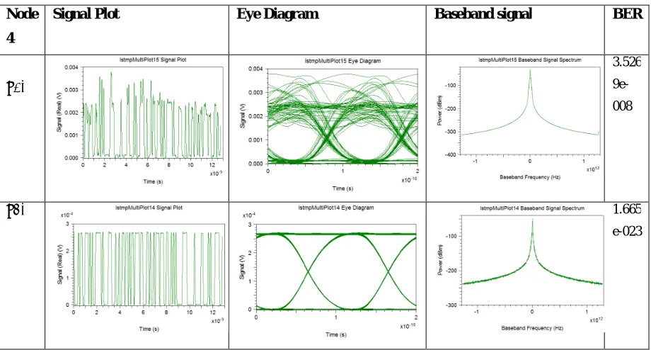
Modulation format NRZ: NODE 4
Node
4
Signal Plot Eye Diagram Baseband signal BER
λ20
3.526
9e-008
λ40 1.665
e-023
Table 3: Result for node 4 with NRZ modulation
In table 3, results are obtained for various lambda at node 4. The eye diagram and baseband signals displays the results based on the signal plot for various lambda. BER changes as per the eye diagram. The results are obtained using NRZ modulation technique. Results at lambda 40 is much better than lambda 20.
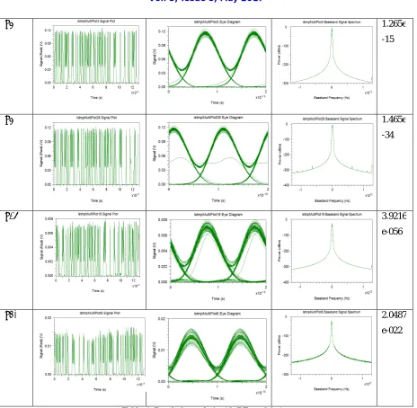
MODULATION FORMAT RZ : NODE 1 Node
1
Signal Plot Eye Diagram Baseband signal BER
λ4
2.8112
e-017
λ3 1.665e
ISSN(Online): 2320-9801
ISSN (Print): 2320-9798
I
nternational
J
ournal of
I
nnovative
R
esearch in
C
omputer
and
C
ommunication
E
ngineering
(An ISO 3297: 2007 Certified Organization) Website: www.ijircce.com
Vol. 5, Issue 5, May 2017
λ5 1.265e
-15
λ5 1.465e
-34
λ16 3.9216
e-056
λ40 2.0487
e-022
Table 4: Result for node 1 with RZ modulation
ISSN(Online): 2320-9801
ISSN (Print): 2320-9798
I
nternational
J
ournal of
I
nnovative
R
esearch in
C
omputer
and
C
ommunication
E
ngineering
(An ISO 3297: 2007 Certified Organization) Website: www.ijircce.com
Vol. 5, Issue 5, May 2017
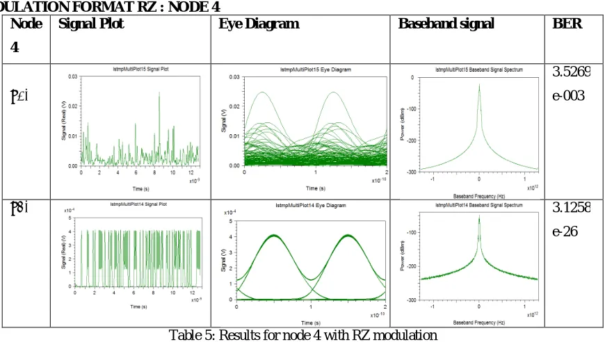
MODULATION FORMAT RZ : NODE 4 Node
4
Signal Plot Eye Diagram Baseband signal BER
λ20
3.5269
e-003
λ40 3.1258
e-26
Table 5: Results for node 4 with RZ modulation
In table 5, the results are obtained for node 4 using RZ modulation technique.In this table, the results on lambda 40 is much better than lambda 20.
VI. CONCLUSION
The system is tested with various parameters like baseband Spectrum, signal data, BER, Eye diagram. The algorithm is applied on RZ and NRZ Modulation format of optical rings in the network in optsim 5.0. We consider all the parameters with Modulation form RZ and NRZ. The value of corresponds signal data baseband spectrum, eye diagram and BER as shown in the above tables. The various performance parameters are analyzed and presented in this dissertation that are obtained from the simulation of this DWDM based metropolitan ring network with 45 channels
starting from wavelength of 1.550µm & channel spacing of 0.0004µm. We considered different wavelength (λ) values
and shows the eye diagram corresponds to these values and accordingly BER value. As results shows our results of ring span length 30 KMS with RZ are much better than NRZ. The result also shows that data rate is much better than the previous data rate.
REFERENCES
1. Sarbjit Singh, "Performance Investigations on DWDM-OADM Optical Ring Network for CRZ Data Format at Different Fiber Length," IJSER, Vol. 2, no. 9, pp. 1-8, 2011.
2. R.D. Rallison and Ralcon Corp, "Dense Wavelength Division Multiplexing DWDM and the Dickson Grating," Wasatch Photonics, 2001. 3. https://en.wikipedia.org/wiki/Return-to-zero
4. https://en.wikipedia.org/wiki/Non-return-to-zero
5. Yi Chen, "Metro Optical Networking,"Bell Labs Technical Journal Vol. 6, pp. 163-186, 1999.
6. S. Jelger, "Photonic Packet WDM Ring Networks Architecture and Performance," IEEE Communication Magazine, Vol. 2, pp. 110-115, 2002.
7. Mark Filer, "Transmission Impairments in DWDM Networks with Reconfigurable Optical Add-Drop Multiplexers," IEEE Journal of Lightwave Technology, Vol. 28, pp. 557-568, 2010.
8. Mohamoud M. A. Eid, "Optical Add Drop Multiplexers with UW-DWDM," International Journal of Computer Science and Telecommunications, Vol. 2, no. 2, pp. 5-13, 2011.
9. Yihong Chen, "Performance of Wavelength Blockers in 80xlO Gb/s Metro Core Add-drop Network," Quantum Electronics and Laser Science Conference, pp. 1726-1728, 2004.
10. http://www.electrooptics.com/products/product_details.php?product_id=657
11. http://www.cisco.com/web/AT/assets/docs/dwdm.pdf