TCP/IP Performance over Wireless Networks
George Xylomenos,
Department of Informatics, Athens University of Economics and Business, Greece,
[email protected]
George C. Polyzos,
Department of Informatics, Athens University of Economics and Business, Greece,
[email protected]
Petri M¨ah¨onen,
Center for Wireless Communications, University of Oulu, Finland,
[email protected]
Mika Saaranen,
Center for Wireless Communications, University of Oulu, Finland,
[email protected]
CHAPTEROBJECTIVES
After completing this chapter, the readers should be able to:
• Obtain a high-level overview of the widely used wireless networks; • Learn the characteristics of wireless links;
• Understand the TCP/IP performance issues over wireless links;
• Discuss some of the key proposals to enhance TCP/IP performance over wireless networks. INTRODUCTION
The current strong drive towards Internet access via mobile terminals, makes the inclusion of wireless systems such as Cellular
Communications (CC) and Wireless Local Area Networks (WLAN) into the mainstream Internet very desirable. CC and WLAN
systems however raise a multitude of performance issues, since environmental conditions and terrestrial obstructions and reflec-tions lead to high and unpredictable error rates. CC and WLAN systems mostly share the characteristics of traditional wireless systems (satellite and terrestrial microwave), such as high error rates. They also share some of the characteristics of wired systems, such as low physical layer propagation delays. As a result, in order to improve their performance, a synthesis of techniques for enhancing the performance of both wired and wireless links is required, that will also take into account the requirements of the TCP/IP protocol suite. In this chapter we present the characteristics and performance limitations of various existing and emerging wireless systems and survey a wide range of approaches for enhancing TCP/IP performance over such links. Although mobility is inherently associated with CC systems, the additional problems that it induces, such as communication pauses whenever mobile devices move between cells, are covered in a separate chapter.
I. WIRELESSNETWORKS
In this section, we first review some of the generic characteristics of CC and WLAN systems, followed by a discussion of some specific wireless networking technologies.
A. Generic Characteristics
The delivery delay for a link layer frame consists of transmission delay, i.e. frame size divided by link speed, propagation
delay, i.e. the time the signal takes to cross the link, and processing delay at the sender and receiver. WLAN and CC links have
similar propagation delays to wired ones, which are much lower than those of satellite links. Unlike wired links though, WLAN and CC links suffer from high error rates. In addition to active sources of interference, CC links are affected by atmospheric conditions and multipath fading due to terrestrial obstructions such as buildings. CC and WLAN links also suffer from indoor multipath fading due to furniture and people. Hence, even without considering mobility, WLAN and CC error behavior can vary in a faster and more unpredictable manner than that of satellite links. Mitigating the adverse effects of interference is a complex task at the physical design level and, in general, the tradeoffs made reflect a system’s usage requirements. In CC systems considerable processing is required in order to reduce the high native error rate of the link, leading to significant processing delays. In WLAN systems on the other hand, the native error rate is much lower, hence error recovery is usually left to higher protocol layers.
Depending on the intended application of a system, its link layer may offer either a private switched circuit service, typical in CC systems, or a shared best effort connectionless service, typical in WLANs. In order to support TCP/IP, the link layer must (at
least) encapsulate IP datagrams into link frames. If the native frame size is too small, then the link layer must also transparently fragment and reassemble IP datagrams. While minimalistic link layers are sufficient to isolate higher layers from low level details in wired links, they may be insufficient for wireless links due to their meager performance. In voice telephony, random frame losses of 1-2% are considered reasonable as they do not cause audible speech degradation [17]. Since physical layer errors are usually clustered, randomization is achieved by interleaving and coding across several frames. Most Internet applications are not error tolerant to that extent though, thus wireless losses impose additional error recovery requirements for higher protocol layers. The traditional Internet approach is to delegate error control to higher (end to end) layers, so as to allow each application to decide if it needs to incur the corresponding error recovery overhead. This is adequate for wireless links where losses due to errors are very rare. For error prone wireless links however, local (link layer) error recovery can be faster and more adaptable to link characteristics. For this reason, voice oriented CC systems offer a non-transparent mode that incorporates link layer error recovery, in addition to their native transparent mode. Some packet oriented WLAN systems similarly provide (optional) error recovery, in order to reduce their error rates. Non-transparent services are not a panacea however, since each error intolerant application may require a different level of reliability. Furthermore, Internet protocols and applications which implement their own error recovery schemes may interact adversely with link layer mechanisms. For example, the transport layer may retransmit delayed packets in parallel with the link layer, thus wasting wireless link bandwidth [9].
B. Wireless Local Area Networks
A characteristic example of WLAN systems is the Lucent (originally NCR) WaveLAN. The original system employed either
direct sequence (DS) or frequency hopping (FH) spread spectrum radios at the 900 MHz or 2.4 GHz frequency bands, offering a
raw bit rate of 2 Mbps. The WaveLAN hardware offers an Ethernet compatible interface to higher layers, i.e. the same headers, CRCs and frame sizes are used, and a connectionless best effort service is provided. WaveLAN networks are broadcast based, so native multicasting and broadcasting are available. The channel is shared using Carrier Sense Multiple Access (CSMA) for access control, i.e. a potential transmitter senses the medium and waits for it to become silent before attempting transmission. Ethernet complements CSMA with Collision Detection (CD), where if multiple transmitters start simultaneously, they detect the collision and abort. In wireless networks collision detection is difficult to implement, as it requires simultaneous transmission and reception in the same band. Hence, the WaveLAN uses Collision Avoidance (CA), where transmitters wait for a random interval after the medium becomes idle before starting transmission. The transmitter which starts first seizes the medium and all others back off, thus reducing the chance of collisions.
The transmission and propagation delays for the WaveLAN are low due to the short range and high bandwidth of the system. Total delivery delay however is unpredictable due to contention, as in wired Ethernet. The system is robust in the presence of narrowband interference and obstructions within its operating range (up to 500 feet) [10]. Typical frame loss rates are less than 2.5% using maximum sized frames (1500 bytes). Interference problems can be caused by other spread spectrum devices and WaveLAN networks operating nearby [11]. Due to timing differences in the firmware and hardware of desktop and laptop interfaces, their throughput is not symmetric [28]. Host processing power also affects throughput and frame loss rates between heterogeneous hosts. Synchronization may lead to excessive collisions during bidirectional communication, which go undetected and must be recovered from at higher layers [30]. A receive threshold mechanism is offered to isolate adjacent WaveLAN networks, but no power control is provided [11]. Later versions of the WaveLAN support multiple frequency bands, to avoid interference between adjacent networks. Connectivity with wired networks can be achieved by using either a router equipped with both wired and wireless interfaces or a transparent bridge.
The success of the original WaveLAN and other similar, but incompatible, systems prompted the IEEE to create the 802.11 standard for WLANs [8]. The standard offers various enhancements over the original WaveLAN. In order to recover from wireless losses, including undetected collisions, transmitters may optionally ask for acknowledgments, so as to transparently retransmit unacknowledged frames at the link layer. Acknowledgments are transmitted in a contention free manner by using a reserved interval, during which regular transmissions are prohibited. To further reduce contention delay, an operating mode is supported where a master host provides WLAN co-ordination, deciding who will transmit next. The original standard specified radios working in the 2.4 GHz frequency band with 1 or 2 Mbps bit rates, in both DS and FH spread spectrum versions. Subsequently, two additional standardization projects were initiated to provide higher speeds. 802.11a uses a high speed OFDM physical layer in the 5 GHz frequency band, providing bit rates ranging between 6 and 54 Mbps. 802.11b was developed to increase bit rates over the existing physical layer and frequency band. Commercial 802.11b solutions provide either 5.5 Mbps or 11 Mbps bit rates, using the 2.4 GHz frequency band.
C. Cellular Communications Networks
Second generation CC systems are digital, unlike first generation ones which were analog. They are characterized by modest bit rates and circuit mode operation, using either TDMA (GSM and IS-54) or CDMA (IS-95) to share the medium. Digital CC links carry small frames which may contain either encoded voice or data. Compared to WLANs, CC systems exhibit higher transmission and propagation delays due to the lower bit rates and longer distances involved. The outdoor CC environment is also harsher, with multipath fading caused by buildings and hills, leading to high error rates. Due to the real time requirements of voice
PHY IP RLP TCP PHY PHY FRA (relay) PHY IP (router) RLP IP TCP
Wireless Host Base Station IWF Wired Host
FRA
FRA Internet
Fig. 1. Connectivity between CC systems and the Internet
System Data Rate Radio Link Protocol Scheme Access Scheme
GSM 9.6 Kbps Selective Repeat ARQ TDMA
IS-54 9.6 Kbps Frame Transmission Order ARQ TDMA IS-95 8.6 Kbps Limited Retransmission ARQ CDMA
TABLE I
SUMMARY OFCCSYSTEM CHARACTERISTICS
telephony, Forward Error Correction (FEC) information is added to each frame, allowing damaged frames to be recovered without retransmissions. Bit errors due to fading are usually bursty, therefore bits from multiple consecutive frames are interleaved before transmission, so as to evenly spread the error bursts and increase the probability of successful recovery. Interleaving considerably increases the processing delay for each frame but manages to reduce the frame loss rate to a level of 1-2% [17], which is not detrimental to voice quality as long as it appears to be random.
Digital CC systems are interconnected to other networks using an Interworking Function (IWF) [1], located at the boundary of the CC system. To interface with analog telephony networks, the IWF converts analog waveforms to digital data and vice versa. To interface with ISDN, the IWF performs rate adaptations and frame conversions, since even though both networks are digital, their implementations differ. In order to directly interoperate with packet data networks such as the Internet, the IWF may also serve as a gateway, as shown in Fig. 1. In this configuration, the wireless host and the IWF communicate via a base station, which simply relays frames between the two. A Radio Link Protocol (RLP) is used between the wireless host and the IWF, offering IP datagram segmentation and reassembly [17]. As a result, the wireless host may exchange IP datagrams with any host on the Internet, using the IWF for routing purposes. The RLP may also provide error recovery in order to hide wireless losses from the Internet [27].
GSM offers 9.6 Kbps full rate channels. The non-transparent mode RLP uses an Automatic Repeat reQuest (ARQ) scheme with 240 bit frames and 24 bit CRCs. It is an HDLC variant with Selective Repeat (SR), i.e. only frames that are actually lost are retransmitted. The RLP causes the native bit error rate of10−3to be reduced to10−8, at the expense of variable throughput and delay due to retransmissions [1]. GSM extensions, discussed later in this chapter, provide higher bandwidth services over the same air interface. IS-54 supports 9.6 Kbps full rate channels. The non-transparent mode RLP uses an advanced ARQ scheme with 256 bit frames and 16 bit CRCs. Each frame separately acknowledges multiple consecutive frames by using a bit map. The sender keeps track of the exact order of original frame transmissions and retransmissions. When a frame is acknowledged, all unacknowledged frames transmitted or retransmitted before it can be safely assumed lost, since the link preserves the transmission sequence [27].
IS-95 supports 8.6 Kbps full rate channels. The non-transparent mode RLP uses 172 bit frames and 16 bit CRCs [17]. Network layer packets are first encapsulated into variable size PPP frames with 16 bit CRCs and then segmented into fixed size RLP frames. This combines the convenience of variable sized packets with the efficient error recovery of fixed size frames. Only negative acknowledgments are used to reduce control overhead. Frames not received after a few retransmissions are dropped, thus this scheme trades off reliability for limited delay variance. The residual packet loss rate is10−4. A higher layer protocol can provide additional recovery, if required. RLP recovery delay in CC systems is added to the delay due to interleaving and FEC coding. Table I summarizes the main characteristics of second generation digital CC systems.
II. TCP PERFORMANCEISSUES OVERWIRELESSLINKS
In this section, we discuss the TCP performance issues raised by the high transmission error rates in wireless links. We first explain the fundamental problem caused by transmission errors, followed by detailed discussions of TCP performance in WLAN
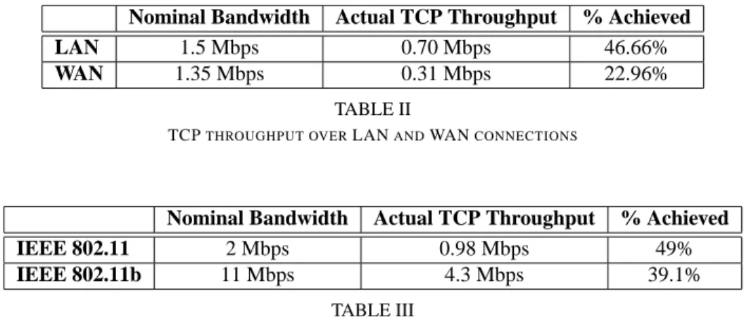
Nominal Bandwidth Actual TCP Throughput % Achieved
LAN 1.5 Mbps 0.70 Mbps 46.66%
WAN 1.35 Mbps 0.31 Mbps 22.96%
TABLE II
TCPTHROUGHPUT OVERLANANDWANCONNECTIONS
Nominal Bandwidth Actual TCP Throughput % Achieved IEEE 802.11 2 Mbps 0.98 Mbps 49%
IEEE 802.11b 11 Mbps 4.3 Mbps 39.1%
TABLE III
TCPTHROUGHPUT OVERIEEE 802.11 LANCONNECTIONS
and CC systems.
A. Inappropriate Reduction of Congestion Window
Transmission errors are the primary source of performance problems for TCP applications in wireless networks. While a few errors per packet may be corrected by low level forward error correction (FEC) codes, more errors may lead to packet corruption. Corrupted packets are discarded without being handed over to TCP, which assumes that these packets were lost. Since TCP takes packet loss as a sign of network congestion, it reacts to these losses by reducing its congestion window. In most cases wireless transmission errors are not related to network congestion, thus these inappropriate reductions of the congestion window lead to uneccessary throughput losses for TCP applications. The resulting throughput degradation can be very severe, depending on factors such as the distance between the sender and receiver and the bandwidth of the communication path. In the following subsections we discuss TCP throughput losses in the WLAN and CC environments.
B. Throughput Loss in WLANs
The WaveLAN suffers from a Frame Error Rate (FER) of 1.55% when transmitting 1400 byte frames over an 85 foot dis-tance, with clustered losses [28]. Reducing the frame size by 300 bytes halves the measured FER, but causes framing overhead to consume a larger fraction of the bandwidth. In shared medium WLANs, forward TCP traffic (data) contends with reverse traffic (acknowledgments). In the WaveLAN this can lead to undetected collisions that significantly increase the FER visible to higher layers [30]. File transfer tests over a WaveLAN with a nominal bandwidth of 1.6 Mbps achieved a throughput of only 1.25 Mbps [28]. This 22% throughput reduction due to a FER of only 1.55% is caused by the frequent invocations of congestion control mechanisms which repeatedly reduce TCP’s transmission rate. If errors were uniformly distributed rather than clustered, throughput would increase to 1.51 Mbps [28]. This is consistent with other experiments showing that TCP performs worse with clustered losses [13].
To illustrate the deterioration of TCP performance due to wireless errors, Table II shows TCP throughput over a LAN path, consisting of a single WLAN, versus a WAN path, consisting of a single WLAN plus fifteen wired links [4]. We show throughput in the absence of any losses, the actual throughput achieved when the WLAN suffers from independent frame losses at a FER of 2.3% for 1400 byte frames, and the percentage of the nominal bandwidth that was achieved. In the WAN case this percentage is half of that in the LAN case. Since TCP recovers from errors via end to end retransmissions, recovery is slower in high delay paths. Table III shows the nominal bandwidth and actual TCP throughput measured over a single link path, using either an IEEE 802.11 or an IEEE 802.11b WLAN. The percentages here show that the high speed link is affected more by losses. Since TCP drastically reduces its throughput after each loss, it takes longer to reach the peak throughput supported by higher speed links.
C. Throughput Loss in Cellular Communication Systems
CC links in transparent (voice) mode suffer from a residual FER of 1-2%, after low level error recovery, despite their short frames [17]. For example, a full rate IS-95 link would segment a 1400 byte IP datagram into 68 frames. Assuming independent frame errors, the probability of a successful packet transmission is 50.49% at a FER of 1%. Frame errors are less bursty than bit errors, because multiple frames are bit interleaved before transmission. Although this process reduces the loss rate and randomizes frame errors, thus avoiding audible speech degradation, it considerably increases processing delay due to interleaving before transmission and de-interleaving after reception. If we reduce the size of IP datagrams in order to reduce the packet loss probability, user data throughput also decreases due to the higher TCP/IP header overhead. TCP/IP header compression may be used over slow CC links, shrinking TCP/IP headers to 3-5 bytes [15]. Header compression however may adversely interact with
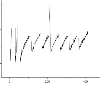
0 200 400 0
7
RTT (s)
Time (s)
Fig. 2. TCP RTT behavior over GSM
TCP error recovery and link layer resets, leading to a loss of synchronization between the compressor and decompressor, thus causing entire windows of TCP data to be dropped [23].
Although the RLP used in the non-transparent mode of GSM usually manages to recover from wireless losses before TCP timers expire [23], it exhibits high and widely varying RTT values. Measurements usingping over a GSM network in San Francisco showed that 95% of the RTT values were around 600 ms with a standard deviation equivalent to 20 ms [22]. Our measurements withpingover GSM networks in Oulu, Helsinki and Berlin, produced similar results but with higher standard deviations. Large file transfer experiments however reveal that RTT can be occasionally much higher with real applications over operational networks, reaching values of up to 12 seconds. Figure 2 shows our RTT measurements from a commercial GSM network in a typical urban environment (Oulu, Finland) during a file transfer session. These RTT values consist of processing time, the2×150ms delay of the GSM channel, plus 250-1250 ms and 35 ms to transmit a packet and its acknowledgement, respectively. Our research confirms the observations of other researchers in that high latency seems to be due to interleaving, rate adaptation, buffering and interfacing between GSM network elements [22].
Increasing the size of the TCP Maximum Transfer Unit (MTU) reduces TCP/IP header overhead, thus improving bulk transfer throughput, but also increases the response time of interactive applications. For example, transmission of a 1500 byte IP datagram over GSM takes around 1.25 seconds, which is unacceptable for interactive applications. Measurements over operational GSM networks show that TCP throughput is optimized for a MTU size of approximately 700 bytes (690 bytes in [21], 720 bytes in our experiments). Our measurements also show that TCP over GSM suffers from occasional interruptions lasting for 6-12 seconds, caused by RLP level disruptions lasting for a couple of seconds. Analysis of this problem suggests that some IP datagrams are buffered and later released out of sequence, a phenomenon that appears in full scale operational GSM networks but is rarely simulated or encountered in small test networks.
Disruptions are also caused by link resets which occur when a RLP frame cannot be transmitted after a few retries, or when a serious protocol violation occurs. This causes the sender and receiver sequence numbers to be reset and flushes all buffers, meaning that in practice the GSM RLP is not fully reliable. To reduce the number of resets, the maximum number of retransmissions (by default 6) can be increased during connection setup [23]. Throughput may also be increased by adapting the GSM RLP frame size. Although small fixed size frames simplify RLP operation and make it more robust in worst case conditions, choosing a frame size appropriate for prevailing conditions can provide throughput improvements of 18-23%, depending on the radio environment [21]. When the end to end path includes multiple wireless links, for example when two hosts on distinct wireless networks com-municate via the Internet, losses accumulate accordingly. This leads to more frequent invocations of TCP congestion control mechanisms which, besides further reducing throughput, also cause wireless links to remain idle for prolonged periods of time, an important issue for circuit switched CC links. Furthermore, when a TCP packet is lost after crossing some wireless links in the path, its retransmission has to cross them again, risking new losses and wasting wireless bandwidth. Losses have more pronounced effects on paths with higher end to end delay which require TCP to maintain large transmission windows to keep data flowing. On such paths TCP also suffers from spurious timeouts, that is, timeouts which would be avoided if the sender waited longer for acknowledgments. In addition to the high and unpredictable delays caused by RLP error recovery, CC systems explicitly allow
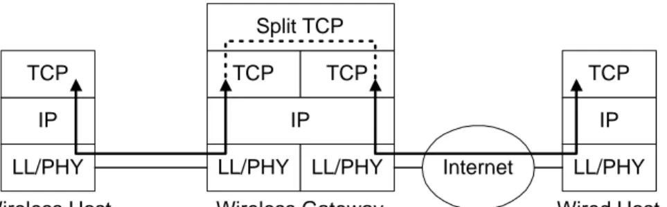
LL/PHY IP TCP
LL/PHY
TCP
Wireless Host Wireless Gateway Wired Host
Internet TCP TCP LL/PHY LL/PHY IP IP Split TCP
Fig. 3. Operation of Split TCP
prolonged disconnections during handoffs, causing numerous spurious timeouts. A related problem, spurious fast retransmits, occurs when packets are reordered beyond the TCP duplicate acknowledgement threshold, an event that occasionally occurs with the GSM RLP.
III. IMPROVINGTCPPERFORMANCE OVER WIRELESS LINKS
Many enhancements have been proposed in order to address TCP throughput problems over wireless links. In this section we discuss some of the key approaches used by these enhancements.
A. Splitting TCP Connections
Since end-to-end retransmissions are slow over longer paths, TCP connections can be split at the wireless gateways connected to both wireless and wired links, as shown in Fig. 3. In this manner, when packets are corrupted by transmission errors over the wireless link, they can be retransmitted over the wireless part of the path only. Indirect-TCP [2], also known as I-TCP, is a TCP enhancement scheme based on the split approach. In this scheme, a software agent at the wireless gateway intercepts TCP connection establishment messages and transparently decomposes the end-to-end connection into separate TCP connections for the wired and wireless parts of the path. The agent bridges these connections by forwarding TCP packets between the two. The connection over the wireless part has a lower delay, leading to faster TCP retransmissions, while the connection over the wired part remains unaware of wireless losses. TCP can also be replaced over the wireless part of the path by another transport protocol providing improved error recovery [32].
The main drawback of the split approach is that it violates end-to-end TCP semantics, since an acknowledgment originating from the wireless gateway may reach the sender before the corresponding data packet reaches its destination. If the gateway crashes after the acknowledgment has been returned to the sender but before the data packet has reached the receiver, the sender will incorrectly assume that the packet has reached its destination safely. Another issue with split schemes is that wireless gateways face significant overhead as packets must undergo TCP processing twice.
B. Snooping TCP at Base Stations
The Snoop TCP scheme has the same objective as split TCP, i.e. to confine retransmissions over the wireless part of the path only. This is achieved by snooping inside TCP connections so as to transparently retransmit corrupted packets without breaking end-to-end TCP semantics [5]. In this scheme a Snoop agent maintains state for each TCP connection traversing the wireless gateway, as shown in Fig. 4. TCP data packets sent from the wired to the wireless host are cached locally, until TCP acknowledgments from the wireless host verify that they were received. When duplicate acknowledgments arrive, indicating that a packet was lost, the packet is retransmitted by the agent from its local cache. The duplicate acknowledgments are then suppressed, i.e. they are not propagated to the wired host, to avoid triggering end-to-end TCP retransmissions and congestion control. The agent also uses local timers in order to detect losses when duplicate acknowledgments themselves are lost. The agent snoops inside TCP packet headers to gather the state information it needs so as to avoid generating its own control messages.
Snoop outperforms split TCP schemes [4], even when TCP with the SACK option is used over the wireless link, without violating TCP semantics, since TCP itself remains unmodified. It also avoids conflicting local and TCP retransmissions [9] by suppressing duplicate TCP acknowledgments whenever it performs local error recovery. With Snoop however only the direction of transfer from the wired to the wireless host benefits from local error recovery, as the TCP receiver is implicitly expected to be located next to the wireless gateway. This is because Snoop relies on TCP acknowledgments to detect whether a packet was received or lost, which are returned very fast when the agent and the TCP receiver are on either side of the wireless link. If a wireless host is sending data to a remote receiver though, TCP acknowledgments are returned too late, and they may even signify congestion losses over a wired link. As a result, Snoop is most profitable when nearly all data flows from the wired towards the wireless host.
LL/PHY IP TCP
LL/PHY
TCP
Wireless Host Wireless Gateway Wired Host
Internet Snoop TCP LL/PHY LL/PHY IP IP Inject data retransmissions Suppress duplicate acknowledgements
Fig. 4. Operation of Snoop TCP
C. Notifying the Causes of Packet Loss
As we discussed earlier, the main reason for degraded TCP performance over wireless links is that TCP cannot determine whether a packet was lost due to transmission errors or due to congestion. Explicit Loss Notification (ELN) [3] is a scheme that enables TCP to distinguish between corruption and congestion induced losses, thus allowing the sender to properly react in each case. Whenever an agent at the wireless gateway, such as the Snoop agent, detects a non congestion related loss, it sets an ELN bit in subsequent TCP headers and propagates it to the receiver, which echoes it back to the sender. The agent uses queue length information to heuristically distinguish congestion from wireless errors. When receiving an ELN notification, the TCP sender at the wireless host retransmits the lost packet without invoking congestion control.
If a significant amount of data originates from the wireless host, as in interactive applications, the ELN scheme can considerably improve performance. This scheme works well in conjunction with Snoop TCP, since both schemes are required in order to perform local retransmission in both directions over the wireless link. However, since lost packets can only be retransmitted after a round trip time has elapsed when an acknowledgment with the ELN bit set is returned, error recovery is slow compared to Snoop TCP. Although ELN is applicable to most topologies, it requires modifications to the transport layers of remote wired hosts, in addition to the agents at wireless gateways.
D. Adding Selective Acknowledgments to TCP
When multiple packets are lost in the same transmission window, the sender can only infer the first packet that was lost from the duplicate acknowledgments returned. After retransmitting the lost packet, the sender must wait for new duplicate acknowledgments to be returned in order to detect the next lost packet. As a result, TCP can only recover from a single loss per RTT [13]. Wireless links may frequently corrupt multiple packets per window, leading to high error recovery delays, especially over high delay paths.
The Selective Acknowledgment (SACK) option for TCP allows each acknowledgment to specify up to three contiguous blocks of data that have been received beyond the last packet in sequence [26]. The sender can thus infer which packets have been lost and retransmit them without waiting for additional duplicate acknowledgments. TCP with the SACK option may be used either end-to-end or only over the wireless part of a split TCP connection, significantly improving throughput in both cases [4]. In the end-to-end case recovery remains quite slow over high delay paths, since the SACK option cannot speed up individual retransmissions. The TCP SACK option is discussed in more detail in Chapter XX.
E. Summary and Comparison of Enhancement Schemes
In order to assess the TCP enhancement schemes discussed above we must consider the following factors:
• End-to-end semantics. A reliable transport protocol must provide true end-to-end semantics, i.e. acknowledgments must
absolutely certify that data packets have reached their destination safely. It is therefore crucial for an enhancement scheme to preserve the end-to-end semantics of TCP.
• IP payload access. Schemes that require the wireless gateway to access the payload of IP datagrams violate the layering
principle. Furthermore, when IPSEC is used for secure communications, the IP payload is encrypted by the end hosts, thus it is not visible to intermediate nodes.
• Wireless gateway overhead. While TCP enhancement schemes may require cooperation from the wireless gateway, they
should keep the corresponding overhead to a minimum. Schemes which require state maintenance for each TCP connection do not scale well for large networks.
• Ease of deployment. Schemes which require modifications to existing infrastructure, for example wired servers and wireless
gateways, are not easy to deploy.
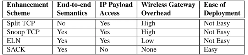
Table IV compares the TCP enhancements discussed above against these factors. With the exception of the SACK option, which is already being deployed but only provides minor improvements, no enhancement scores well in all areas. This implies
Enhancement End-to-end IP Payload Wireless Gateway Ease of Scheme Semantics Access Overhead Deployment
Split TCP No Yes High Not Easy
Snoop TCP Yes Yes High Not Easy
ELN Yes Yes Low Not Easy
SACK Yes No None Easy
TABLE IV
COMPARISON OFTCPENHANCEMENTS FOR WIRELESS LINKS
that we must always make a tradeoff between these factors. Which factor should take precedence over the rest depends on the networking scenario. For example, if a TCP enhancement solution is needed for a private financial transaction network, then modifications in the existing infrastructure may not a be a serious obstacle, while preservation of end-to-end semantics may be of prime importance due to high reliability requirements.
IV. WIRELESSSYSTEMEVOLUTION ANDTCP/IP
As wireless networks continue to evolve, TCP/IP performance will remain an important issue. In this section we briefy describe the evolutionary paths of CC and WLAN systems and discuss the future of TCP/IP in the forthcoming wireless era.
A. Trends in Cellular Communication Systems
The trend for CC systems is to provide higher bit rates and better support for packet data services, so as to become more attractive for Internet access. In order to leverage existing infrastructure, at a first stage second generation CC systems will be extended. In GSM each frequency band is shared via TDMA, with each TDMA frame consisting of 8 slots, i.e. each frequency band supports 8 GSM circuits. The High Speed Circuit Switched Data (HSCSD) system is an extension of GSM providing bit rates of up to 56 Kbps. HSCSD reserves multiple slots per frame, in effect multiplexing several GSM circuits into a high speed logical circuit. The General Packet Radio Service (GPRS) system is a packet switched extension of GSM [16]. GPRS dynamically reserves multiple slots per frame in order to send data packets at a high speed, thus allowing the channel to be shared by multiple wireless hosts. As a result, GPRS enables wireless hosts to be constantly attached to the Internet, at a fraction of the cost of a dedicated CC circuit. GPRS also supports multiple physical layer encoding schemes, providing user bit rates of up to 160 Kbps, depending on radio conditions. The actual bit rate available also depends on the capabilities of the wireless host, i.e. how many slots per frame it can handle. Early experiments and simulations show that Internet packet loss rates over GPRS will be around 2%.
Higher speeds will eventually be offered by the next generation of CC systems. The third generation European CC system, UMTS, is based on wideband CDMA, supporting both circuit and packet switched modes at various bit rates. Phase one includes services similar to GPRS, providing bit rates of up to 384 Kbps. Wideband CDMA allows the bit rate to be varied, depending on user requirements and radio conditions, with forthcoming phases promising bit rates of up to 2 Mbps in limited areas. The EDGE/IS-136 HS system, an extension of GSM, will provide bit rates of 270-722 Kbps, or even over 2 Mbps in limited areas. By increasing the number of radio cells in a given area, more bandwidth can be allocated to each user, but the cost of the radio infrastructure increases proportionately. As a result, the highest data rates will only be offered within limited areas where the cost of providing these reduced size microcells will be justifiable, for example in densely populated areas. Sparsely populated areas on the other hand will be covered by terrestrial or satellite systems using very large cells, or macrocells.
B. Trends in Wireless LAN Systems
The trend for WLAN systems is to provide higher speeds and support for mobility between adjacent networks, with each network essentially becoming a microcell. An extensive amount of work has also been performed towards developing more efficient Medium Access Control (MAC) protocols for shared access WLANs [7]. A multitude of very short range (in room) systems, or Personal Area Networks (PANs), have been designed for low bit rates. The coverage area of a PAN is commonly referred to as a picocell. Bluetooth is a FH spread spectrum system providing bit rates of 400-700 Kbps within its operating range of a few meters. Bluetooth provides connectivity between diverse wireless devices that may dynamically enter and leave the PAN. Its TCP performance should be similar to low end WLANs. The IEEE 802.15 project which specifies a PAN standard based (partially) on Bluetooth is working on its radio link level interoperability with IEEE 802.11. For very high speeds, the Local
Multipoint Distribution Service (LMDS) will offer broadband wireless Internet access using the 28 or 40 GHz frequency bands,
with an operating range of 1–3 kilometers. LMDS is a Wireless Local Loop (WLL) system providing 1-2 GHz of bandwidth to
C. TCP/IP over Heterogeneous Wireless Systems
The design of each wireless system reflects specific tradeoffs between infrastructure cost, data rate and coverage area. Due to the diversity of existing and future application requirements, we expect that, at least for the foreseeable future, multiple such systems will co-exist. The key characteristic underlying both existing and emerging wireless systems is support for the TCP/IP protocol suite, which will allow them to communicate with each other by becoming part of the Internet. The next step is to provide direct interoperability between wireless systems by allowing users to transparently move not only between cells within the same system, but also from one system to another. This would enable users to dynamically select the system best suited to their requirements, among those available in their present location. The result could be unified hierarchical cellular systems, with large cells being overlaid by multiple smaller cells in areas with high user densities [18].
Hierarchical cellular systems must be carefully designed to avoid increasing the gravity of handoff induced problems. The small size of microcells will lead to more frequent handoffs while their high data rates may potentially lead to increased losses during each handoff. Furthermore, handoffs between overlaid cells may also dramatically change the performance of underlying wireless links, leading to considerable variations in the characteristics of end to end paths. While the performance difference between a microcell and a macrocell cannot be masked by either link or transport layer mechanisms, co-operation between layers could enable higher layers to better adapt their behavior to lower layer capabilities. The emerging concept of software radios which allow the configuration of physical and link layer parameters in real time [14] is expected to further promote link adaptivity, hence protocol adaptivity will become even more critical in the future.
Intensive research has been directed towards adaptive link layers that provide information to higher layers in an orderly fashion, so as to support network independent adaptivity mechanisms at higher layers. The Multi Service Link Layer (MSLL) approach provides multiple link services to higher layers, with each one serving the requirements of a particular class of applications [31]. The Wireless Internet NEtwork (WINE) project is also studying protocol adaptivity and link dependent configuration so as to optimize IP performance over wireless links, without exposing lower layer details to TCP. A protocol enhancing proxy approach has been developed, the Wireless Adaptation Layer (WAL), to handle automatic adaptivity. Both schemes export standardized link performance metrics, so as to facilitate the operation of adaptive higher layer protocols.
V. FURTHERREADING
• A good coverage of wireless network architectures can be found in [19], [29]
• End-to-end TCP semantics can be preserved in Split TCP schemes by synchronizing the acknowledgments between the two connections [25]. This however exposes the recovery delays of the wireless part of the path to the other side, which adapts its transmission rate accordingly, thus reducing throughput.
• During periods of persistent losses, TCP timeouts can be avoided if an agent at the wireless gateway chokes the TCP sender by transparently closing the receiver’s advertised window [6]. The sender then freezes all pending timers and enters the
persist mode, where it periodically probes the receiver’s window without reducing its transmission rate.
• The spurious timeouts and fast retransmissions due to delayed lower layer retransmissions and packet reordering in wireless links can be avoided by using the TCP timestamp option in outgoing packets and echoing these timestamps in the corrre-sponding acknowledgments. This allows spurious timeouts and fast retransmissions to be easily avoided without changing TCP semantics [20].
• Many link layer schemes have been proposed in order to improve TCP performance over wireless links [12], [21], [23]. These schemes provide a more reliable link to higher protocol layers. In [31], the authors have shown that TCP unaware link layer schemes can considerably outperform Snoop TCP when both communicating hosts are wireless or when most data flows from a wireless to a wired host.
VI. SUMMARY
The performance of the TCP/IP protocol suite over Cellular Communications and Wireless Local Area Network systems is far from satisfactory, due to their relatively high error rates. TCP throughput decreases dramatically even at modest error rates, due to its assumption that all losses are due to congestion which leads to drastic reductions of its transmission rate after wireless losses. These performance problems are more pronounced with higher speed wireless links and longer end to end paths. There exists a wide variety of performance enhancement schemes which either modify TCP so as to better recover from wireless losses or provide link layer error recovery so as to hide these losses from TCP. Wireless system evolution is headed towards higher data rates and the co-existence of heterogeneous systems. It seems that in order to tackle the challenges of emerging wireless architectures we need improved co-operation between protocol layers that will enable each layer to better adapt to the fast changing wireless environment of the future.
VII. REVIEWQUESTIONS
1) The IEEE 802.11 WLAN standard and most CC system RLPs support link layer acknowledgments and retransmissions for error recovery. Are there any applications that would not want to use these options?
2) The CSMA/CA access protocol does not detect collisions as CSMA/CD does. How does this limitation affect link layer and transport layer performance?
3) The IS-54 RLP assumes that if a frame is acknowledged, all frames that were transmitted earlier but are still unacknowledged must have been lost. Why TCP cannot do the same?
4) Why is TCP performance more affected by losses over high delay and high speed network paths? 5) Which are the main factors leading to TCP throughput degradations over wireless links?
6) With some Split TCP schemes, a data packet can be acknowledged without first reaching its destination. Why is this a problem?
7) Why TCP without Selective Acknowledgments can only recover from a single packet loss per round trip time? 8) Why does Snoop suppress the duplicate TCP acknowledgements it receives after retransmitting lost packets?
VIII. HANDS-ONPROJECTS
1) Implement Snoop TCP, I-TCP and TCP with ELN in the freely available ns-2 simulator. Conduct simulation experiments to measure and compare TCP performance using these three schemes. Write a report describing your results.
2) Implement Snoop TCP, I-TCP and TCP with ELN in the freely available FreeBSD operating system. Build a wireless test-bed and conduct experiments to measure and compare TCP performance using these three schemes. Write a report comparing your experimental results with those you obtained using the ns-2 simulator.
REFERENCES
[1] T. Alanko, M. Kojo, H. Laamanen, M. Liljeberg, M. Moilanen, and K. Raatikainen. Measured performance of data transmission over cellular telephone networks. Computer Communications Review, 24(5):24–44, October 1994.
[2] A. Bakre and B.R. Badrinath. Implementation and performance evaluation of Indirect-TCP. IEEE Transactions on Computers, 46(3):260–278, March 1997. [3] H. Balakrishnan and R. Katz. Explicit loss notification and wireless web performance. In IEEE Globecom, November 1998.
[4] H. Balakrishnan, V.N. Padmanabhan, S. Seshan, and R.H. Katz. A comparison of mechanisms for improving TCP performance over wireless links. In
Proceedings of the ACM SIGCOMM ’96, pages 256–269, August 1996.
[5] H. Balakrishnan, S. Seshan, and R.H. Katz. Improving reliable transport and handoff performance in cellular wireless networks. Wireless Networks, 1(4):469–481, 1995.
[6] K. Brown and S. Singh. M-TCP: TCP for mobile cellular networks. Computer Communications Review, 27(5):19–43, October 1997.
[7] A. Chandra, V. Gummalla, and J.O. Limb. Wireless medium access control protocols. IEEE Communications Surveys and Tutorials, 3(2), 2000.
[8] B.P. Crow, I. Widjaja, J. Geun Kim, and P.T. Sakai. IEEE 802.11 wireless local area networks. IEEE Communications Magazine, 35(9):116–126, September 1997.
[9] A. DeSimone, M. C. Chuah, and O.C. Yue. Throughput performance of transport-layer protocols over wireless LANs. In Proceedings of the IEEE
GLOBECOM ’93, pages 542–549, December 1993.
[10] D. Duchamp and N.F. Reynolds. Measured performance of a wireless LAN. In Proceedings of the 17th IEEE Conference on Local Computer Networks, pages 494–499, September 1992.
[11] D. Eckhardt and P. Steenkiste. Measurement and analysis of the error characteristics of an in-building wireless network. In Proceedings of the ACM
SIGCOMM ’96, pages 243–254, August 1996.
[12] D. Eckhardt and P. Steenkiste. Improving wireless LAN performance via adaptive local error control. In Proceedings of the ICNP’98, 1998. [13] K. Fall and S. Floyd. Simulation based comparisons of Tahoe, Reno and SACK TCP. Computer Communications Review, 26(3):5–21, July 1996. [14] J. Mitola III and G.Q. Maguire Jr. Cognitive radio: making software radios more personal. IEEE Personal Communications, 6(4):13–18, August 1999. [15] V. Jacobson. Compressing TCP/IP headers for low-speed serial links. Internet Request For Comments, February 1990. RFC 1144.
[16] R. Kalden, I. Meirick, and M. Meyer. Wireless Internet access based on GPRS. IEEE Personal Communications, 7(2):8–18, April 2000.
[17] P. Karn. The Qualcomm CDMA digital cellular system. In Proceedings of the USENIX Mobile and Location-Independent Computing Symposium, pages 35–39, August 1993.
[18] R.H. Katz and E.A. Brewer. The case for wireless overlay networks. Proceedings of the SPIE, 2667:77–88, 1996. [19] Y-B. Lin and I. Chlamtac. Wireless and Mobile Network Architectures. John Wiley and Sons, 2000.
[20] R. Ludwig and R.H. Katz. The Eifel algorithm: making TCP robust against spurious retransmissions. Computer Communications Review, 30(1):30–36, January 2000.
[21] R. Ludwig, A. Konrad, and A.D. Joseph. Optimizing the end-to-end performance of reliable flows over wireless links. In Proceedings of the ACM/IEEE
MOBICOM ’99, pages 113–119, August 1999.
[22] R. Ludwig and B. Rathonyi. Link layer enhancements for TCP/IP over GSM. In Proceedings of the IEEE INFOCOM ’99, pages 415–422, March 1999. [23] R. Ludwig, B. Rathonyi, A. Konrad, K. Oden, and A.D. Joseph. Multi-layer tracing of TCP over a reliable wireless link. In Proceedings of the ACM
SIGMETRICS ’99, pages 144–154, June 1999.
[24] P. M¨ah¨onen, T. Saarinen, Z. Shelby, and L. Mu˜noz. Wireless Internet over LMDS: Architecture and experimental implementation. IEEE Communications
Magazine, 39(5):126–132, May 2001.
[25] D. Maltz and P. Bhagwat. MSOCKS: An architecture for transport layer mobility. In Proceedings of the IEEE INFOCOM ’98, pages 1037–1045, March 1998.
[26] M. Mathis, J. Mahdavi, S. Floyd, and A. Romanow. TCP selective acknowledgment options. Internet Request For Comments, October 1996. RFC 2018. [27] S. Nanda, R. Ejzak, and B.T. Doshi. A retransmission scheme for circuit-mode data on wireless links. IEEE Journal on Selected Areas in Communications,
12(8):1338–1352, October 1994.
[28] G. T. Nguyen, R. H. Katz, B. Noble, and M. Satyanarayanan. A trace-based approach for modeling wireless channel behavior. In Proceedings of the Winter
Simulation Conference, pages 597–604, December 1996.
[29] J. Schiller. Mobile Communications. Addison-Wesley, 2000.
[30] G. Xylomenos and G. C. Polyzos. TCP and UDP performance over a wireless LAN. In Proceedings of the IEEE INFOCOM ’99, pages 439–446, March 1999.
[31] G. Xylomenos and G.C. Polyzos. Link layer support for Quality of Service on wireless Internet links. IEEE Personal Communications, 6(5):52–60, October 1999.
[32] R. Yavatkar and N. Bhagawat. Improving end-to-end performance of TCP over mobile internetworks. In Proceedings of the IEEE Workshop on Mobile